Latest Software Blog Posts
Bug Notification: Non-Seismic Lateral Companion Loads Amplified for Seismic Effects
Be aware of this for shear wall designs resisting lateral earth pressures
In cases where a bug or other issue is found in the MASS software, announcements are posted on the software’s known bugs page, as well as on this page here. It is always encouraged that suspected bugs are submitted by engineers through technical support.
As covered in a series of posts linked here, MASS takes seismic considerations into account when checking a shear wall element’s capacity under diagonal in-plane shear and sliding shear. This notification in particular deals with an issue regarding how one of these requirements is checked and implemented into the software.
Disclaimer: This post is exclusively intended to provide insight into the approach taken by the MASS design software in interpreting a CSA S304-14 code compliant seismic design. It is up to the professional discretion of the designer to input an appropriate layout, boundary and loading conditions, interpret the results, and determine how they should be incorporated into their designs. As per the end user license agreement (and also recommended within PEO’s guidelines for using engineering software), a tool cannot be considered competent and reliance on a tool does not relieve the user of responsibility.
As always, please do not hesitate to contact MASS technical support with any questions or concerns about any software results.
Summary
MASS currently amplifies all lateral loads for seismic load cases in determining the required factored shear resistance that must be designed for. This process is covered in a series of articles available linked here. While the most earthquake related load combinations are a combination of a lateral seismic force plus a series of axial loads such as Dead, Live, and Snow type loads, there are other cases possible with companion loads applying additional non-seismic lateral loading. MASS scales up the entire lateral in-plane load rather than just the seismic component of that load. This can result in designs where non-seismic lateral companion loads are unintentionally amplified, resulting in a higher than expected factored shear resistance requirement.
Background Information
A full explanation of the process used to scale up earthquake forces for the purposes of in-plane shear design is covered in further detail here. All references are from CSA S304-14 unless otherwise stated.
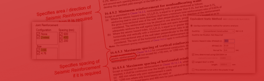
Note: there are different versions of this requirement depending on the ductility of the SFRS being designed.
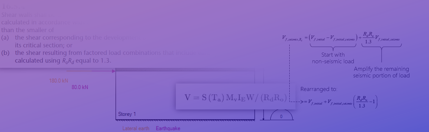
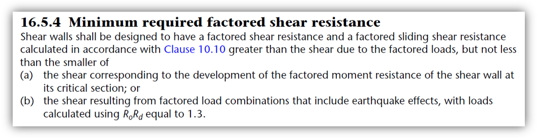
The requirement that a shear wall must be able to resist the loading in the scenario where the product of RdRo is reduced down to 1.3 is something that MASS does consider. For part (b) of this seismic consideration, the software superficially increases the required factored shear that must be designed for under the assumption that earthquake type loads are inversely proportional to the overstrength and ductility SFRS force modification factors.
Note how any calculated seismic shear forces are divided by the product of of Rd and Ro in the highlighted expressions below. Taken from NBCC 2015 4.1.8.11(b):
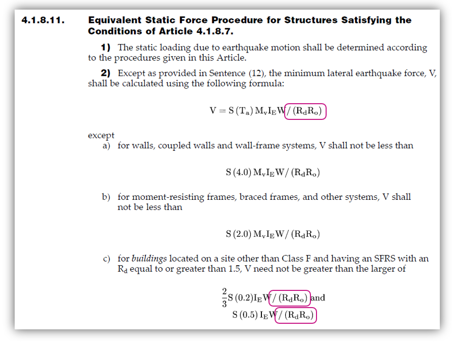
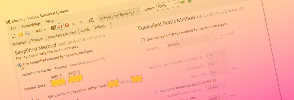
If using the simplified method, a single Rs replaces RdRo and is 1.0 for unreinforced designs and 1.5 for reinforced designs. This does not need to be considered in the implementation of this clause because designs qualifying for the simplified method are also exempt from satisfying CSA S304-14: 16 as the seismic hazard risk is below an established threshold.
Based on the selected level of ductility, MASS determines the amplified earthquake force by multiplying the unfactored load input by the user by the product of RdRo and then divides that value by the substituted value of 1.3 from Cl. 16.5.4 (b). Currently, this is done without added consideration of how much of this lateral load is resulting from a seismic source which is the source of this issue.
As previously mentioned, the majority of seismic load combinations that have the added requirements from CSA S304-14 Clause 16 consist of solely seismic lateral loading plus a combination of axial companion loads such as dead and snow. The exception to this is a case where there is also an in-plane lateral earth pressure applied to a shear wall. Functionally, this is always present similar to a dead load but the key difference is that the lateral earth pressure is not impacted by replacing RdRo by 1.3 and should not be amplified.
As a result, the software incorrectly scales up the factored shear force under the seismic load case in question rather than only the portion of that applied factored shear force that originates from a seismic load source.
Types of Affected Designs
This issue will come into play whenever designing for a seismic load combination where there are lateral loads originating from different load types. For example, consider the case of a building where a portion of the bottom storey is below grade. Any shear wall elements laterally supporting exterior walls are likely to resist some lateral earth pressure which is included as a companion load to the applied earthquake loads resisted by that shear wall element.
In this case, MASS evaluates all applicable limits when determining whether or not to scale up the factored shear force and by how much. If there is no significant flexural overstrength in the design, in-plane shear will still be correctly scaled upward as the RdRo taken as 1.3 can be thought of as an upward bound, not governing designs in situations like these.
As flexural overstrength increases, it becomes more and more likely that the upper limit on shear force amplification for seismic effects will govern design. When only a portion of the shear force under consideration is coming from actual earthquake loading, this limit can be incorrectly (and punitively) high. This results in an excessively conservative shear force amplification requirement that MASS attempts to satisfy.
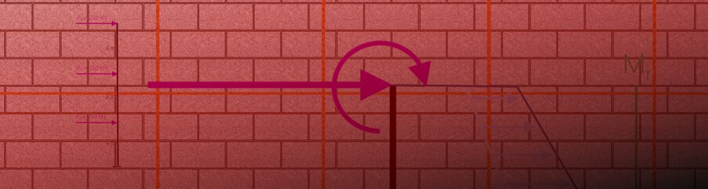
Example Multi-storey Elevation
Consider the shear wall elevation shown below with the following unfactored loads applied to each storey:
- Loads applied to the roof level (elevation: 8.2 m):
- 40 kN Earthquake load
- Loads applied to the top of the second storey (elevation: 5.4 m):
- 100 kN Earthquake load
- Loads applied to the top of the bottom storey (elevation: 2.8 m):
- 80 kN Earthquake load
- 180 kN Lateral Earth load
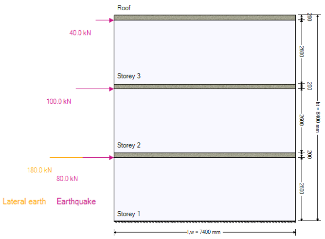
At the base storey, there is a total of 400kN of factored shear force applied to the top of the section, based on load combination 1.0D + 1.0H + 1.0E.
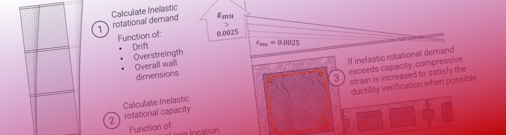
To satisfy sliding shear, MASS places more vertical bars than what is required for moment design since the software will not automatically address this in the shear design stage (vertical bars are placed during moment and deflection design).
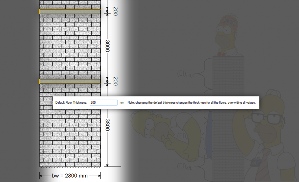
In this example, the following cross section is used:
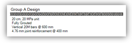
The wall is designed using a 20 cm, 20 MPa block, fully grouted, with vertical 20M bars spaced at 600 mm and extra heavy duty joint reinforcement every other course.
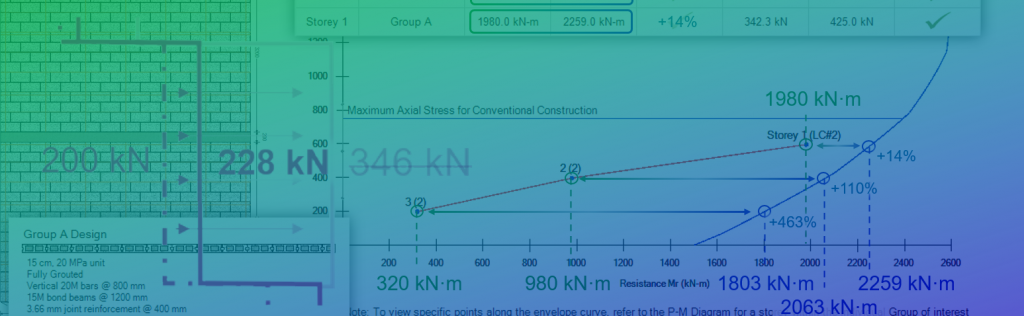
Taking seismic considerations into account for shear, the factored shear force that MASS designs for is amplified by 73%, bringing the original 400 kN value all the way up to 692 kN – a significant difference! While some shear amplification is legitimately required, this value shown by MASS is higher than required.
These results can be checked under the Simplified Results, Shear tab of the results window, as seen below:
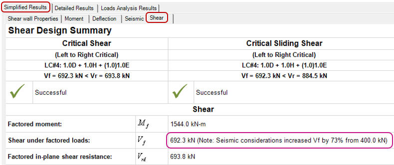
Looking at the lateral load causing that factored 400 kN of initial shear force to be amplified, it can be divided into seismic and non-seismic components. In this case, only 220 kN or 55% of that factored shear force should be impacted by substituting RdRo = 1.3 in accordance with clause 16.5.4 (b).
This value can be recalculated by only amplifying the portion of shear force originating from earthquake type loads.
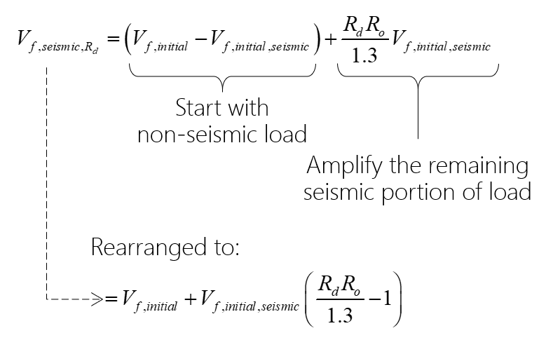
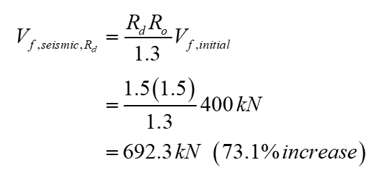
In this example, the way this requirement is currently implemented (and to be changed) is shown below:
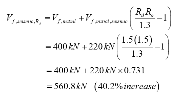
Compare this to the reduction when correctly applied:
Note: these are only showing part (b) of the shear amplification and the results must be compared to other applicable factors such as flexural overdesign in part (a).
The total shear amplification drops from 73% down to 40%, reducing the factored shear force that must be designed to resist. Note that even in the updated expression, the seismic portion of shear is amplified by the same percentage, only it is now correctly attributed to no longer amplify the entire shear force applied.
In cases where there is difficulty finding a satisfactory design for in-plane shear, this expression can be used to calculate the correct shear amplification in the meantime, before a minor software release update.
Final Thoughts and Designer Strategy Suggestions
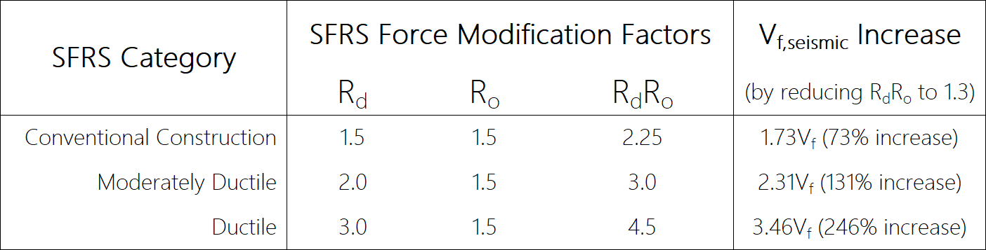
The RdRo only applies if flexural overdesign is very large. For conventional construction, this amplification kicks in at 73% but it gets even higher for moderately ductile or ductile SFRS designations. The table below is taken from the main summary series linked here.
This issue in the software concerns what can be thought of as an upper limit to shear force amplification. Designing shear walls that are more efficiently configured to resist flexure under seismic loading conditions is an effective strategy to avoid excessive shear amplification.
Sometimes large flexural overdesign ratios are justified and unavoidable. This can be warranted in cases where sliding shear is critical so additional vertical bars are needed to provide a stronger clamping force for friction to be more effective. There could also be non-seismic load combinations that control the design, where in-plane shear considerations are at the mercy of an other load considerations.
That all being said, reducing flexural overdesign in most cases will result in this limit no longer governing, further reducing shear amplification.
Side Note/Bonus Suggestion: If satisfying shear is still an issue, consider fully grouting the wall. This can be done using the drop-down selection menu in the Masonry section of the Materials input window. There is a γg factor (gamma g) that takes partial grouting into account which can be especially punitive to shear wall designs.
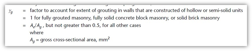
This is a factor at the end of the shear equation that acts like a giant switch, with the shear resistance of the masonry going from 50% (or less) to 100% when the wall is fully grouted. The effect is dramatic on design results. When MASS is going through and iterating cross sectional properties, the software doesn’t apply critical thought or engineering judgement to take into consideration the reason for failure. As a result, what often happens is the design results with a section where bars are placed in every cell. This is solely a function of incrementing reinforcement before block size, strength, or grouting pattern and yielding a higher in-plane shear resistance to satisfy all requirements.
In any case, it is possible that the amplified shear force seen in MASS may be higher than actually required for design. Being aware of this issue will hopefully help the user apply a critical look to design results to prevent further degrees of overdesign.
Still have questions?
CMDC is always evaluating the calculations and processes that are used by the MASS software. It is part of the ongoing technical support as the authorized service provider for National Masonry Design Programs (NMDP – publisher of MASS) that these issues continue to be identified and addressed as they are found. Please keep an eye out for new version updates which address issues such as these.
If there is any uncertainty regarding the calculations or results from the MASS software, please do not hesitate to contact MASS support. This software is a tool that must be well understood by the engineers performing the designs.