

Shear Wall Design Strategy
Shear Wall Design Strategy
This section provides users with information on how MASS obtains a shear wall design. Specifically, this section discusses the design philosophy employed in the moment design step, as well as the shear design step. This information allows the designer to manipulate the shear wall module with ease.
A shear wall web can be designed in three ways: by placing steel at a uniform spacing along the length of the wall (‘Uniform steel spacing’ mode), by allowing the program to include additional steel at each end of the shear wall web (‘Concentrated end steel’ mode), or by specifying the steel properties in each cell individually (‘Cell-by-cell design’ mode). For all three modes, the factored moment, Mf, is compared with the moment resistance, Mr. In order achieve a successful design Mr ≥ Mf.
Uniform Steel Spacing Mode
The uniform steel spacing mode is the default design mode in the shear wall module. Using this mode, the program iterates through the selected properties in the following order; the bar size, number of bars per cell, bar spacing, block strength, and block size. This is summarized in Figure 5-105: Moment Design Hierarchy for Shear Wall Module (Uniform Steel Spacing Mode)-. At each iteration, the factored moment is compared with the moment resistance.
Figure 5-105: Moment Design Hierarchy for Shear Wall Module (Uniform Steel Spacing Mode)
The program begins by iterating up through the selected bar sizes, while fixing: the number of bars per cell, the bar spacing, the block strength and the block size. For the initial configuration, the program uses the smallest block size and the weakest block selected by users. If the masonry unit properties are left unchanged by users, the smallest block size, by default, is a 10 cm unit, and the weakest block strength, by default, is 15 MPa. The least number of bars per cell, by default, is zero. In this case, the wall is unreinforced, and thus the bar spacing, and bar size is not a consideration. If this configuration does not yield a successful moment design, the program attempts the design with one bar per cell, the largest bar spacing, and the smallest bar size. If the vertical steel properties remain unchanged by users, the largest bar spacing, by default, is 2400 mm, and the smallest bar size, by default, is a No. 10 bar.
![]() Note: The transition from zero bars per cell (resulting in an unreinforced wall) to one or two bars per cell (resulting in a reinforced wall) appears to occurs seamlessly. This transition however, has some important design consequences; unreinforced walls are designed in accordance to Clause 7 of CSA S304-14 and reinforced walls are designed in accordance to Clause 10 of CSA S304-14.
Note: The transition from zero bars per cell (resulting in an unreinforced wall) to one or two bars per cell (resulting in a reinforced wall) appears to occurs seamlessly. This transition however, has some important design consequences; unreinforced walls are designed in accordance to Clause 7 of CSA S304-14 and reinforced walls are designed in accordance to Clause 10 of CSA S304-14.
If a successful design is not achieved with the largest bar size selected, the program iterates up to the next number of bars per cell, and begins reiterating through the bar size possibilities again, while fixing: the bar spacing, the block strength and the block size. If a successful design is not achieved with the largest number of bars per cell permitted, the program iterates down to the next largest bar spacing, and begins reiterating through the number of bars per cell, and the bar size possibilities, while fixing: the block strength and the block size.
For a uniform steel configuration, bars of the same size are placed at the specified spacing uniformly throughout the length of the web.
The bars are placed symmetrically about the centre of the web, beginning with a bar on each end. For a web with an odd number of cells, and a bar spacing of 1.2 metres for example, this is readily achieved as illustrated in Figure 5-106: Vertical Bars Spaced Uniformly Along Entire Web-.
![]()
Figure 5-106: Vertical Bars Spaced Uniformly Along Entire Web
In some cases the vertical reinforcing bars cannot be evenly spaced throughout the length of the web. In these cases, the bars are still placed symmetrically about the centre of the web, beginning with a bar on each end of the web. However, bars that are placed closest to the line of symmetry may have a reduced spacing, if necessary. For example, the web illustrated in Figure 5-101: Bars Spaced Uniformly from Either Side of the Web- contains an even number of cells. In order meet a bar spacing of 1.2 metres for instance, two bars at a spacing of Lunit,web/2 are placed at the line of symmetry.
![]()
Figure 5-107: Bars Spaced Uniformly from Either Side of the Web
If a successful design is not achieved with the smallest bar spacing permitted, the program iterates up to the next weakest block strength, and begins reiterating through the bar spacing, the number of bars per cell, and the bar size possibilities, while fixing: the block size. If a successful design is not achieved with the strongest block permitted, the program iterates up to the next smallest block size, and begins reiterating through the bar spacing, the number of bars per cell, and the bar size possibilities, while fixing: the block size. This iteration procedure continues until a successful design is reached, or all block sizes are exhausted.
![]() Note: Due to the large number of iterations the program performs, it may take up to several minutes to reach a successful design. If the program requires more than several seconds to reach a solution, the smaller weaker blocks, or larger spacing and smaller bar sizes do not provide enough capacity. In this case, users can easily de-select some of the early iterations in the midst of the design process. This will significantly speed up the program.
Note: Due to the large number of iterations the program performs, it may take up to several minutes to reach a successful design. If the program requires more than several seconds to reach a solution, the smaller weaker blocks, or larger spacing and smaller bar sizes do not provide enough capacity. In this case, users can easily de-select some of the early iterations in the midst of the design process. This will significantly speed up the program.
![]() Note: MASS can only iterate through the properties that are checked-on. Hence, de-selecting all masonry properties and reinforcement configurations, except for one of each type, converts the program into an analysis tool, rather than a design tool. The program simply determines the moment resistance, Mr , and compare that value to the factored moment, Mr . The program thus becomes an analysis tool, rather than a design tool.
Note: MASS can only iterate through the properties that are checked-on. Hence, de-selecting all masonry properties and reinforcement configurations, except for one of each type, converts the program into an analysis tool, rather than a design tool. The program simply determines the moment resistance, Mr , and compare that value to the factored moment, Mr . The program thus becomes an analysis tool, rather than a design tool.
Concentrated End Steel Mode
The concentrated end steel mode must be specifically chosen by users, as discussed in the Moment Design section. Using this mode, the program iterates through the selected web
properties in the following order; the bar size, number of bars per cell, bar spacing, block size, and block strength. This is summarized in Figure 5-108: Design Hierarchy for Shear Wall Module (Concentrated End Steel Mode)-. At each iteration, the magnified factored moment is compared with the moment resistance.

Figure 5-108: Design Hierarchy for Shear Wall Module (Concentrated End Steel Mode)
The program begins with the configuration yielded when using the uniform steel spacing mode. The program then iterates up through the selected bar sizes, while fixing: the number of reinforced cells at the ends, the number of bars per cell in the web, the bar spacing in the central portion of the web, the block strength and the block size in the web. For the initial configuration the program uses the smallest block size and the weakest block selected by users. If the masonry unit properties are left unchanged by users, the smallest block size, by default, is a 10 cm unit, the weakest block strength, by default, is 15 MPa. The least number of bars per cell, by default, is zero. In this case, the wall is unreinforced, and thus the bar spacing, and bar size is not a consideration.
![]() Note: The transition from zero bars per cell (resulting in an unreinforced wall) to one or two bars per cell (resulting in a reinforced wall) appears to occur seamlessly. This transition however, has some important design consequences; unreinforced walls are designed in accordance to Clause 7 of CSA S304-14 and reinforced walls are designed in accordance to Clause 10 of CSA S304-14.
Note: The transition from zero bars per cell (resulting in an unreinforced wall) to one or two bars per cell (resulting in a reinforced wall) appears to occur seamlessly. This transition however, has some important design consequences; unreinforced walls are designed in accordance to Clause 7 of CSA S304-14 and reinforced walls are designed in accordance to Clause 10 of CSA S304-14.
If this configuration does not yield a successful moment design, the program attempts the design with one bar per cell, the largest bar spacing, and the smallest bar size. If the vertical steel properties remain unchanged by users, the largest bar spacing, by default, is 2400 mm, and the smallest bar size, by default, is a No. 10 bar.
Initially, the program places the bars at a specified spacing uniformly throughout the length of the web. The bars are placed symmetrically about the centre of the web, beginning with a bar on each end. In the case where bars cannot be evenly spaced throughout the length of the web, bars closest to the line of symmetry can be spaced closer, if necessary, than the specified spacing, as was illustrated in Figure 5-107: Bars Spaced Uniformly from Either Side of the Web. However, unlike in the uniform steel configuration, if the current uniform spacing and bar size does not provide enough capacity, the program can increase the bar size, or the number of bars at the two ends of the web to provide more capacity. The bar size at the ends begins with the same bar size used in the remainder of the wall (based on the initial uniform spacing design). The bar size is increased until a successful design is achieved, or until all bar sizes are exhausted and the program has still not found a successful design. If a successful design has not been found, then the program increases the number of reinforced cells at the ends. For example, if the web shown in Figure 5-109: Web with No. 30 Bars Spaced at 1.2 m-, with No. 30 bars at 1.2 metres, does not provide enough capacity, the program attempts to place another bar on either end, as shown in Figure 5-110: Web with No. 30 Bars Spaced at 1.2 m, with Additional Concentrated Steel at the Ends-.
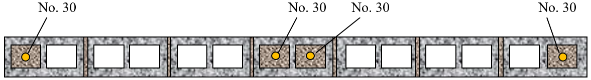
Figure 5-109: Web with No. 30 Bars Spaced at 1.2 m
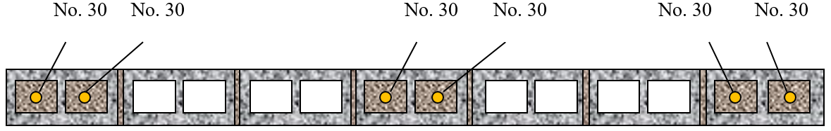 Figure 5-110: Web with No. 30 Bars Spaced at 1.2 m, with Additional Concentrated Steel at the Ends
The bar size at the ends can be increased until the desired capacity is met, or until the maximum percentage of steel has been placed at the end. For the example above, assuming a concentrated steel maximum of 25%, the maximum amount of steel permitted is:
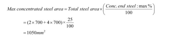
For the spacing shown in Figure 5-103: Web with No. 30 Bars Spaced at 1.2 m-, the most amount of steel that can be placed at the ends is 2 No. 25s =982 mm2, as can be seen in Table 5-4: Maximum Concentrated Steel Area-.
Table 5-4: Maximum Concentrated Steel Area
|
Bar Size |
Area of Steel at Each End |
Comparison with Maximum Concentrated Steel Area |
|
2 No. 10’s |
~200mm2 |
200mm2 < 1050mm2 |
|
2 No. 15’s |
~400mm2 |
400mm2 < 1050mm2 |
|
2 No. 20’s |
~600mm2 |
600mm2 < 1050mm2 |
|
2 No. 25’s |
~1000mm2 |
~1000mm2 < 1050mm2 |
|
2 No. 30’s |
~1400mm2 |
1400mm2 < 1050mm2 |
Thus, rather than adding a No. 30 bar on either side (as demonstrated in Figure 5-110: Web with No. 30 Bars Spaced at 1.2 m, with Additional Concentrated Steel at the Ends), the program advances to the next iteration property and decreases the spacing of the bars along the length of the web. At this decreased spacing, with a fixed block size and strength, the program reiterates through the bar size at the ends, and the numbers of reinforced cells at the ends.
![]() Note: The ends may be increased by more than just one cell length per iteration. Consider the case where the program would place a single bar in an empty cell between two grouted cells. Rather than having two consecutively reinforced cells at the end, the ends now contain three consecutively reinforced cells. The bar in the neighbouring cell is altered to match the bar size at the ends. This ensures that all the bar sizes at the ends are the same, and it addresses potential constructability concerns.
Note: The ends may be increased by more than just one cell length per iteration. Consider the case where the program would place a single bar in an empty cell between two grouted cells. Rather than having two consecutively reinforced cells at the end, the ends now contain three consecutively reinforced cells. The bar in the neighbouring cell is altered to match the bar size at the ends. This ensures that all the bar sizes at the ends are the same, and it addresses potential constructability concerns.
If a successful design is not achieved with the smallest bar spacing permitted, the program iterates up to the next weakest block strength, and begins reiterating through the bar size at the ends, the number of reinforced cells at the ends, the bar spacing, the number of bars per cell, and the bar size possibilities, while fixing the block size. This iteration procedure continues until a successful design is reached, or all block sizes are exhausted.
Cell-by-Cell Design Mode
As mentioned in the Moment Design section, users can also design the shear wall by specifying the vertical steel properties in each cell along the length of the web. This option is available once the program has provided an initial design using the uniform steel spacing mode (or the concentrated end steel mode, if selected by users). The number of bars per cell, the bar size, and the location of the bar are provided based on the initial design, and can be altered on a cell-by-cell basis by users.
If users chooses to design the web of the shear wall on a cell-by-cell basis, only the block size and block strength can be iterated through by the program, as shown in Figure 5-111: Design Hierarchy for Shear Wall Module (Cell-by-Cell Mode)-.

Figure 5-111: Design Hierarchy for Shear Wall Module (Cell-by-Cell Mode)
If a successful design is not achieved with the current set of user selections, the program iterates through the remaining block strengths, while fixing: the block size. If a successful design is not achieved with the strongest block permitted, the program iterates up to the next smallest block size, and begins iterating through block strengths. This iteration procedure continues until a successful design is reached, or all block sizes are exhausted.
After the axial and moment design are completed, the program calculates the in-plane shear and in-plane sliding shear resistance of the wall, and verifies that they are larger than the in-plane factored shear. During the shear design step, the sliding shear resistance (at each course i), Vri, and the diagonal shear resistance, Vr, are calculated using the shear wall properties that provided during the moment design. The sliding shear resistance (at each course ) is compared with the factored shear (at each course). For shear walls, shear calculations are performed in the same manner for unreinforced shear walls as reinforced shear walls. CSA S304-14: 10.10.2.1 is used to determine the diagonal shear, and CSA S304-14: 10.10.5.1 is used to determine the sliding shear.
The sliding shear resistance is determined at masonry joints, only. The program does not calculate the sliding shear at the base of the wall. It is the responsibility of users to verify the sliding shear resistance at the base of the wall, taking into account the friction coefficient of materials in contact (masonry-to-smooth concrete or bare steel), and dowels (if any).
In order achieve a successful shear design; Vri≥Vfi and Vr≥Vf,max. To meet this requirement the program performs the design by iterating through the number of bond beams, the bond beam spacing, bond beam bar size, number of joint reinforcement bars, joint reinforcement spacing, and the number joint reinforcement size. This is summarized in Figure 5-112: Shear Design Hierarchy for the Shear Wall Module-. At each iteration, the factored shear is compared with the shear resistance.

Figure 5-112: Shear Design Hierarchy for the Shear Wall Module
The program commences by iterating up through the selected joint reinforcement sizes, while fixing: the joint reinforcement spacing, the number of joint reinforcement wires, the bond beam bar size, the bond beam spacing, and the number of bond beams. The program commences with the smallest joint reinforcement size and the largest joint reinforcement spacing, based on the selections provided by users. If the horizontal steel properties are left unchanged by users, the smallest joint reinforcement, by default, is a 3.66 mm (standard, side wire or cross wire), the largest joint reinforcement spacing, by default, is 600 mm. The least number of joint reinforcement wires, by default, is zero. If the horizontal steel properties are left unchanged by users, the smallest bond beam bar size, by default, is a No. 10. The largest bond beam spacing, by default, is 1200 mm (although users are permitted to select a bond beam bar spacing of up to 2400 mm).
If the number of bond beams is zero, and the number of joint reinforcement wires is zero, the wall is horizontally unreinforced, and thus the bond beam bar spacing, joint reinforcement bar spacing, and horizontal reinforcement sizes are not a consideration. If a successful shear design is not achieved with no shear reinforcement, the number of joint reinforcement wires is increased to two wires. The joint reinforcement sizes are cycled up until a successful design is achieved, or until the program reaches the largest joint reinforcement size available.
If the design is not successful, the joint reinforcement spacing is cycled down, beginning at the largest permitted spacing. If the reinforcement spacing and joint reinforcement size iterations do not provide enough shear resistance, the number of bond beams is increased from zero to one, and the bond beam bar size is cycled up. If the shear resistance requirements are not met, then the bond beam spacing is initially fixed to the largest spacing, as permitted by users. The bond beam spacing is cycled through from the largest permitted spacing to the smallest spacing. If the iteration has reached the smallest joint reinforcement and bond beam spacing, and the largest joint reinforcement size and bond beam bar size, the shear wall fails in shear.
Continue Reading: Shear Wall Deflection