

Shear Wall Design Steps
Shear Wall Design Steps
This section provides in-depth detail on the steps necessary to successfully complete a shear wall design using the MASS software package.
Contents
There are four design steps necessary to complete a shear wall design: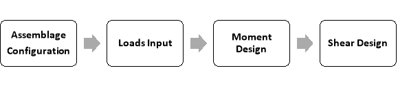 Assemblage configuration is the first design step, where the material properties of the shear wall (and its flanges or boundary elements if applicable) are entered or selected. Loads input is the second design step, where the loads and moments are applied to the shear wall. Using these loads, the program determines the corresponding load combinations. Moment design is the third design step. At this stage, the program designs the shear wall such that the moment resistance of the shear wall exceeds the maximum factored moment determined at the loads input stage. Shear design is the forth design step. At this stage, the program designs the shear wall such that the shear resistance exceeds the sliding shear and shear due to the factored applied loading. This may require the addition horizontal reinforcement (bond beams or joint reinforcement). Further detailing is left to the designer.
Assemblage Configuration (Web)
Assemblage configuration is the first step in developing a shear wall design. The program automatically begins at this step when a new assemblage is opened, as can be seen in Figure 5‑1: Assemblage Configuration: Web, Flanges and Boundary Elements‑, where the Assemblage Configuration button is outlined in red. The assemblage configurations step allows users to enter the material properties of the shear wall. For the shear wall module only, the assemblage configuration step contains three tabs: the Materials tab, the Flanges tab, and the Boundary Elements tab as shown in Figure 5‑1: Assemblage Configuration: Web, Flanges and Boundary Elements‑.
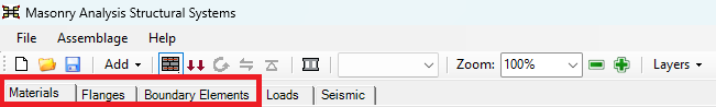 Figure 5‑1: Assemblage Configuration: Web, Flanges and Boundary Elements
Within the materials tab, users can specify the masonry properties of the shear wall web. For a shear wall with no flanges, the Flange tab can be ignored. This subsection deals with the masonry properties of the web only. For entering the masonry properties of a flange, click here to view the section on Assemblage Configuration (Flanges). For entering the masonry properties of a boundary element, click here to view the section on Assemblage Configuration (Boundary Elements). To specify the properties of a shear wall web:
- Enter the shear wall web dimensions (length, height in mm)
- Select the type of masonry unit (hollow or semi-solid concrete)
- Choose the size and strength of the unit
- Choose the appropriate end fixities
- Provide masonry properties
- Provide steel properties
- Choose to smear the grout (optional)
- Read the constructability concerns
Web Dimensions
In the case of a shear wall, two dimensions must be entered: the length, the height and the total height (in the case of a wall within a multi-storey system). A shear wall with a height of 3000 mm has been specified in Figure 5‑2: Entering Shear Wall Dimensions‑. The program provides a default length of 3000 mm. This default value has been changed to 6000 mm. The thickness of web is defaulted to 290 mm thickness in the drawing, until the program is provided with a design selection. As soon as the assemblage dimensions are entered, an assemblage drawing is available.
Notice that when performing the assemblage configuration design step, the Assemblage Configuration button is outlined in blue.
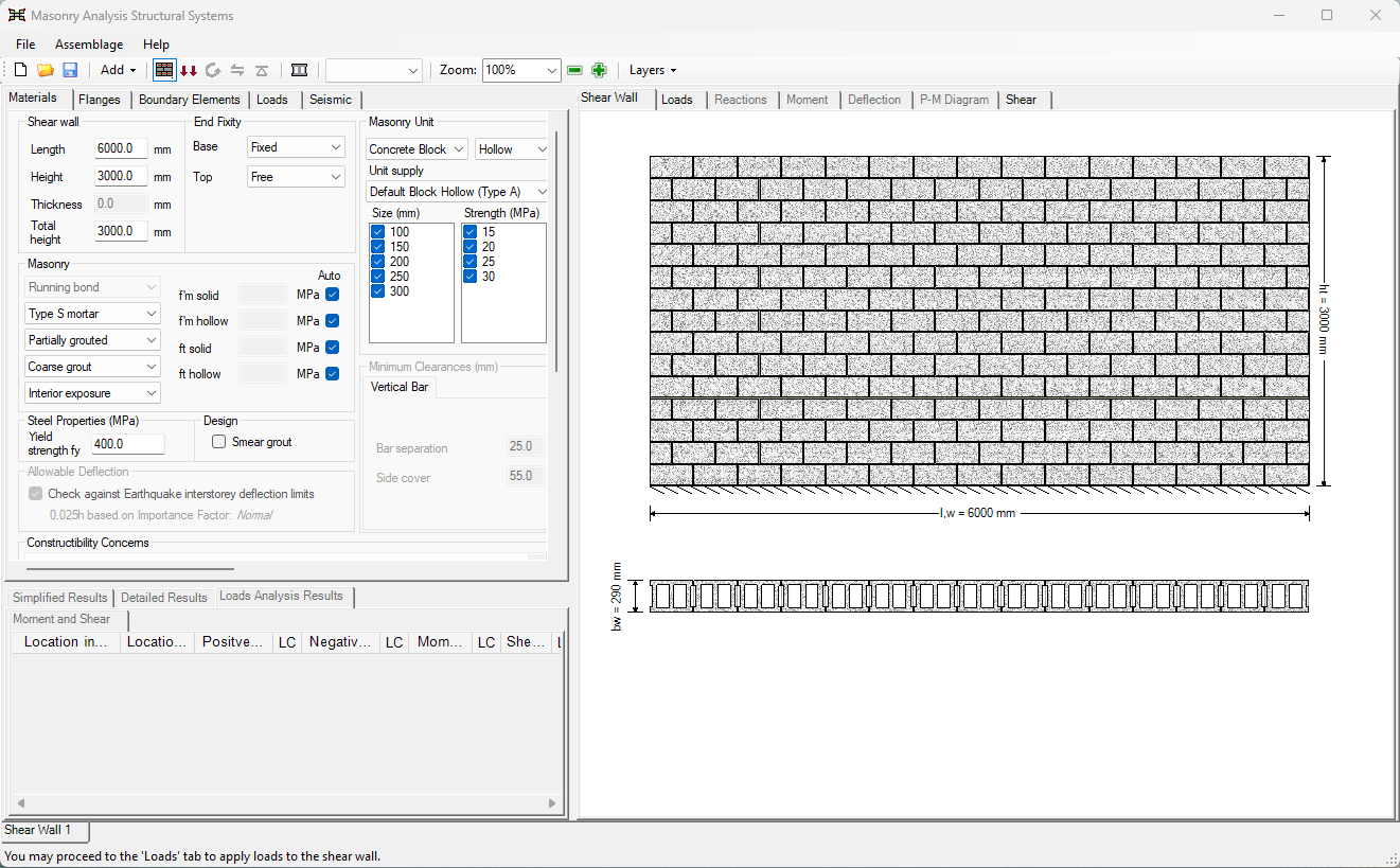 Figure 5‑2: Entering Shear Wall Dimensions
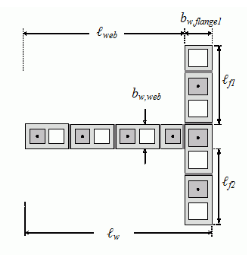
All dimensions in the program are entered in millimeters. The length refers to the length of the web. In the absence of flanges or boundary elements, this length is also the total length of the shear wall. However, in the presence of flanges or boundary elements, the total length of the wall becomes:

![]() Note: MASS does not automatically include the mortar joint between the end of the web, and a flange. For the units to not be shaded in red indicating that cuts are required, space for a 10mm mortar joint should be included in the length of the web.
Note: MASS does not automatically include the mortar joint between the end of the web, and a flange. For the units to not be shaded in red indicating that cuts are required, space for a 10mm mortar joint should be included in the length of the web.
In order include this mortar joint, the length of the web can be increased by 10 mm. For instance, for a shear wall with fifteen 40 cm blocks along its length, the cumulative length of the web is 6000 mm. To include mortar, enter a web length of 6010 mm. Press Enter on the keyboard.
Partial cells along the web length are permitted but not encouraged. For walls that are not modular in web length, cut-off blocks are placed at the right side of the web of the shear wall and are outlined in red to indicate a constructability concern. The program always forces the left side of the wall to start at either the end of a unit or at the half length of a unit. Non-modular blocks are outlined in red indicating a construction concern.
![]() Note: Dimensions that are non-modular require units to be cut on-site. It is up to the designer to decide whether the mortar bed at the top of the wall is considered part of the wall. The program recognizes either a modular height or a modular height minus 10 mm, or anything in between, as being composed of full and not cut blocks, however the value entered is used for calculations.
Note: Dimensions that are non-modular require units to be cut on-site. It is up to the designer to decide whether the mortar bed at the top of the wall is considered part of the wall. The program recognizes either a modular height or a modular height minus 10 mm, or anything in between, as being composed of full and not cut blocks, however the value entered is used for calculations.
When the height/length ratio is less than 1 (that is: hw<ℓw) and the shear wall is cantilevered (support condition at base is fixed and at top is free), the wall is referred to as a squat wall. MASS allows the design of squat walls. For more information on squat walls refer to the Detailed Design section.
Below the length and height textboxes is the textbox for the thickness of the web.This textbox is grey and therefore disabled. This thickness of the web depends on the masonry unit size selected. The upper limit on the web thickness is the thickness of the largest block permissible which is typically 290 mm (unless a custom size is added to the masonry unit database). The lower limit on the web thickness for a single-wythe wall is indirectly imposed for reinforced walls by the need to fit vertical steel within the block width (refer to the ‘Minimum Clearances’ heading by clicking here). The lower limit for unreinforced masonry is the smallest block size in the masonry unit database. Upon the completion of the moment design step, the masonry unit size used in the design is displayed in this textbox (as seen in Figure 5‑53: Moment Design – Successful).
As soon as the assemblage dimensions are entered, and assemblage drawing is available, as shown in Figure 5‑2: Entering Shear Wall Dimensions‑. This drawing is updated during each design step to reflect any changes to the shear wall design.
Type of Masonry Unit
For the shear wall module, MASS supports the use of blocks only (masonry bricks are not included). Block types with the following solidity are provided: hollow, semi-solid, solid, half-high, half-block, and bond block. The default unit types are shown in Figure 5‑3: Entering the Dimensions of a Shear Wall.
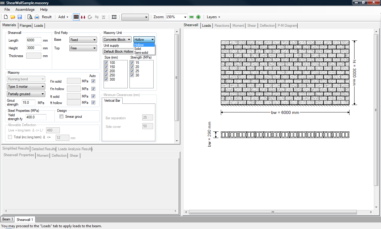 Figure 5‑3: Entering the Dimensions of a Shear Wall
Users can also specify the unit supply of the masonry unit. This unit supply list contains default block types based on the solidity selected. For a block with a hollow solidity, the unit supplies available by default are shown in Figure 5‑4: Choosing the Unit Supply of the Masonry Unit‑.
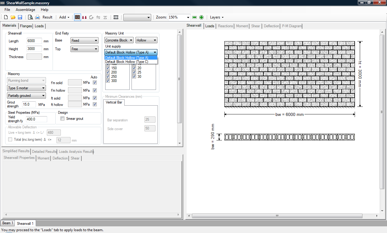 Figure 5‑4: Choosing the Unit Supply of the Masonry Unit
The unit supply list also includes customized units if they have been entered into the masonry unit database.
![]() Note: In addition to the available block types, users are also able to create a new unit with customized properties) using the Masonry Unit Database. For more information, click here.
Note: In addition to the available block types, users are also able to create a new unit with customized properties) using the Masonry Unit Database. For more information, click here.
For instructions on how to view the properties of a specific unit, refer to the Masonry Unit Database section. The classification of concrete block properties is governed by CSA A165.1-4 Table 1 to Table 4.
Unit Size and Strength
Nominal dimensions of a masonry unit include ½ mortar bed thickness on each surface, adding 10 mm to each actual dimension. The actual thickness of a masonry unit, t, is 10mm less than the minimal thickness. In the program, the size of the unit refers to the nominal thickness (t + 10mm mortar joint) of the masonry unit.
The strength selection pertains to the compressive strength of the unit, f’m. The compressive strength of the unit is the resistance to pressure applied to the net area of the block perpendicular to the bed plane that is applied. Therefore it depends on the compressive strength of the material, the percent solid, and the shape of the unit. This compressive strength of a unit, f’unit, contributes to the determination of compressive strength of the masonry assemblage, f’m (governed by CSA S304-14, Tables 3 and 4). The compressive strength of an assemblage takes into account the mortar and grout,.
The unit strengths available for design depend on the supplier, however, the values provided in the program by default are the typical values used in masonry construction. By default, the program leaves all possible sizes and strengths checked-on, as is illustrated in Figure 5‑2: Entering Shear Wall Dimensions‑.
The program iterates through these possible values, beginning with the smallest and weakest block, and selects the first of these that meets the engineering requirements. The default concrete block sizes available include 10, 15, 20, 25, and 30 cm units. The default block strengths include 15, 20, 25, and 30 MPa.
![]() Note: In some locations in Canada 30 MPa blocks may not be readily available.
Note: In some locations in Canada 30 MPa blocks may not be readily available.
Other strengths are possible and are accommodated by the program through the masonry unit database (refer to the Masonry Unit Database section). MASS does not support using brick units for shear wall design. Users can also select the specific size and strength of the unit, by checking-off all other unit sizes and strengths.
End Fixity
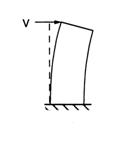
The support conditions should be specified prior to the application of any loads. For shear walls, the support condition permitted at the base is fixed. The possible support conditions at the top are free and fixed(R). The free condition simply refers to a shear wall that is cantilevered, as shown in Figure 5‑5: Shear Wall with a Free End Fixity at the Top [1]. The fixed(R) specifies that the support condition is fixed in rotation, but not translation, as shown in Figure 5‑6: Shear Wall with a Fixed (R) End Fixity at the Top [1].
|
|
|

This support condition is typically applied to a pier, where it is assumed that the heavy masonry above the prier prevents the pier’s rotation, as illustrated in Figure 5‑7: Pier in a Perforated Shear Wall‑. This support condition is selected at the discretion of the designer.
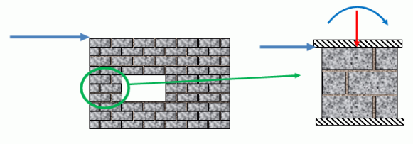 Figure 5‑7: Pier in a Perforated Shear Wall
To select the bottom end fixity of a shear wall using MASS, click on the drop-down box marked ‘Base’. To select the top end fixity of a shear wall using MASS, click on the drop-down box marked ‘Top’, as shown in Figure 5‑8: Choosing the End Fixities of a Shear Wall‑. A shear wall with fixed-free support conditions is shown in the top window of Figure 5‑8: Choosing the End Fixities of a Shear Wall. The support conditions chosen are reflected in the shear wall drawing in the window on the right side, as shown in Figure 5‑8: Choosing the End Fixities of a Shear Wall.
 Figure 5‑8: Choosing the End Fixities of a Shear Wall
Masonry Properties
As can be seen in Figure 5‑9: Masonry Properties Options‑, users can specify additional masonry properties such as; the bond pattern, mortar type, grouting pattern, compressive strength of the assemblage, tensile strength of assemblage, and grout strength.
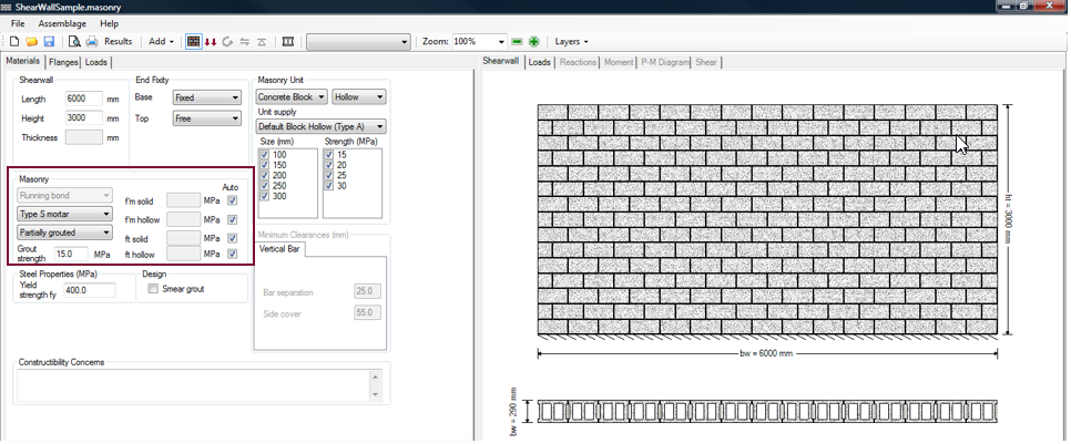 Figure 5‑9: Masonry Properties Options
MASS only supports a running bond configuration in the shear wall module. Running bond configuration occurs when blocks in a higher course are placed such that the mid-section of each block is aligned with the vertical mortar joints of the lower course. Alternative alignments are also permitted in masonry, but are not supported by MASS. For instance, blocks can be laid with one-third overlap. A one-fourth overlap is however the minimum.
The mortar type in a shear wall module can be changed using the drop-down box shown in Figure 5‑10: Choosing the Mortar Type‑.
 Figure 5‑10: Choosing the Mortar Type
In general, there are five grades of masonry mortar (Types M, S, N, O, and K) that are distinguished by their proportions of lime, cement, and sand, and the resulting properties in terms of compressive strength, ductility, and workability. Only Type S and Type N are currently recommended for structural work, and therefore are the only two mortar types available within the program. Type S is a high compressive strength mortar recommended for structural applications. Type N is a more workable but lower compressive strength mortar used for low-stress bearing and veneer applications. Although strong, Type M has high vapour porosity and poor workability. Type O and Type K are primarily for restoration work.
![]() Note: Types M, S, N, O, and K are arbitrary letters, every other letter taken from the words Mason Work and have no meaning in terms of the mortar properties.
Note: Types M, S, N, O, and K are arbitrary letters, every other letter taken from the words Mason Work and have no meaning in terms of the mortar properties.
In the shear wall module, the grouting pattern is selected using drop-down box shown in Figure 5‑11: Choosing the Grouting Pattern‑.
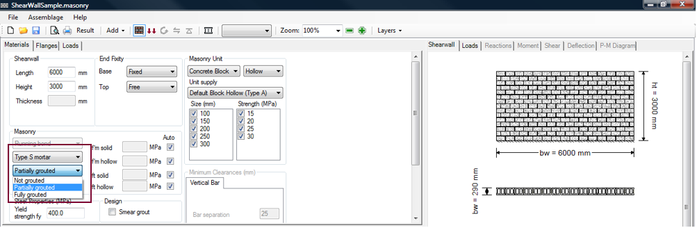 Figure 5‑11: Choosing the Grouting Pattern
The grouting pattern depends on the masonry unit type selected by users. For hollow concrete blocks, the grouting patterns permitted are: not grouted, partially grouted, and fully grouted. For semi-solid concrete blocks, the grouting patterns permitted are: not grouted, partially grouted, and fully grouted. For solid concrete blocks, the grouting patter permitted is: not grouted. The grouting patterns permitted for each block type are summarized in Table 5‑1: Grouting Pattern and Compressive & Tensile Strength Selections Available Based on the Masonry Unit Solidity‑.
Not grouted simply means the shear wall does not contain any grout. This grouting pattern is applicable for shear walls composed of hollow block, semi-solid block, or solid block.
![]() Note: Grout is required for all reinforced cells. By selecting not grouted, users exclude the possibility of a shear wall with vertical and/or horizontal reinforcement.
Note: Grout is required for all reinforced cells. By selecting not grouted, users exclude the possibility of a shear wall with vertical and/or horizontal reinforcement.
Partially grouted refers to some cells being grouted, as shown in Figure 5‑12: Partially Grouted Shear Wall Web‑.
![]() Figure 5‑12: Partially Grouted Shear Wall Web
Figure 5‑12: Partially Grouted Shear Wall Web
This grouting pattern is applicable for shear walls composed of either hollow block or semi-solid block. In the case of partially grouted walls, only cells that contain reinforcement are grouted. Therefore, the grouted cell spacing is equal to the reinforcement spacing. Partial cells (which are always placed at the right end of the web) are assigned the grouting condition of its neighbouring cell.
In fully grouted masonry, all cells must be grouted, independent of the presence of reinforcement or its spacing. This grouting pattern is applicable for walls composed of hollow block, or semi-solid block.
![]() Note: Fully grouting a semi-solid concrete block wall provides the same fire resistance as a fully grouted hollow block wall, but typically provides less strength and is more difficult to construct.Consider using a hollow concrete block instead of a semi-solid concrete block in this instance.
Note: Fully grouting a semi-solid concrete block wall provides the same fire resistance as a fully grouted hollow block wall, but typically provides less strength and is more difficult to construct.Consider using a hollow concrete block instead of a semi-solid concrete block in this instance.
![]() Note: Choosing a partially grouted or fully grouted pattern does not necessarily result in a reinforced shear wall. MASS design routine begins by attempting to design a shear wall without reinforcement, because this type of wall configuration is typically cheaper and faster to construct. It is possible to choose to detail a wall that is specifically reinforced in the moment design step (refer to the ‘Vertical Steel’ section).
Note: Choosing a partially grouted or fully grouted pattern does not necessarily result in a reinforced shear wall. MASS design routine begins by attempting to design a shear wall without reinforcement, because this type of wall configuration is typically cheaper and faster to construct. It is possible to choose to detail a wall that is specifically reinforced in the moment design step (refer to the ‘Vertical Steel’ section).
The compressive and tensile strength values of an assemblage are calculated automatically within the program using Table 3 and Table 4 in CSA S304, and depend on the masonry unit type selected and the grouting conditions. Upon the completion of the moment design step, (or as soon as users select only one masonry unit size and strength), the compressive and tensile strength used in the design are displayed in the textbox (as seen in Figure 5‑53: Moment Design (Successful)‑).
Users are permitted to override selected compressive and tensile strength values. Depending on the type of unit selected (hollow, solid or semi-solid), and the grouting conditions specified (not grouted, partially grouted, fully grouted), users are permitted to enter only certain types of assemblage compressive strengths. This relationship is summarized in Table 5‑1: Grouting Pattern and Compressive & Tensile Strength Selections Available Based on the Masonry Unit Solidity‑. The values entered by users must be based on prism tests that have been performed in accordance to CSA S304-14: 5.1 and CSA S304-14: 5.2.
Table 5‑1: Grouting Pattern and Compressive & Tensile Strength Selections Available Based on the Masonry Unit Solidity
|
Masonry Unit Type |
Grouting Pattern |
User Override of Compressive Strengths |
User Override of Tensile Strengths |
|
Hollow
|
Not Grouted |
|
|
| Partially Grouted |
|
|
|
| Fully Grouted |
|
|
|
|
Semi-Solid |
Not Grouted |
|
|
| Partially Grouted |
|
|
|
| Fully Grouted |
|
|
|
|
Solid |
Not Grouted |
|
|
Notice in Table 5‑1: Grouting Pattern and Compressive & Tensile Strength Selections Available Based on the Masonry Unit Solidity‑, for semi-solid masonry units, f’m solid and ft hollow values are used independent of the grouting. Due to lack of supporting research CSA S304-14 takes a conservative approach, and restricts the compressive strength to f’m solid because it is the smaller of f’m solid and f’m hollow. CSA S304-14 also restricts the tensile strength to ft hollow because it is the smaller of ft solid and ft hollow.
To override a compressive strength value, uncheck the ‘Auto’ box next to the value to be entered, and enter the compressive strength value into the textbox. Press Enter on the keyboard. For example, for a hollow wall, fully grouted, users are permitted to enter prism test values for f’m solid, f’m hollow, ft grouted, and ft hollow. Uncheck the ‘Auto’ check-box next to each value. Then enter appropriate compressive strength and tensile strength values. Press Enter on the keyboard.
It is common to perform prism tests to gain additional capacity. Because masonry typically fail under compression, designers primarily perform prism tests to determine compressive strength values. However, if users check-on the ‘Auto’ box, the program requires users to provide both the compressive and tensile strengths. It is acceptable to use compressive strength values determined using prism tests, but enter tensile strength values using Table 5 from CSA S304-14.
![]() Note: The compressive strength values used in the program are limited to 40 MPa. The tensile strengths used in the program are limited to 2 MPa.
Note: The compressive strength values used in the program are limited to 40 MPa. The tensile strengths used in the program are limited to 2 MPa.
For the remainder of this chapter, the ‘Auto’ check-box is checked-on.
Steel Properties
At this stage, the only steel property users are permitted to specify is the steel yield strength. There are three popular grades of steel: 300, 400, and 500. Only the 400-grade is widely available and is used in the vast majority of applications. 300-grade reinforcement bars are available in 10 mm and 15 mm sizes. 500-grade reinforcement bars in all sizes are available through special order to steel mills. The yield strength is defaulted to 400 MPa, as shown in Figure 5‑11: Choosing the Grouting Pattern‑. To alter the yield strength, enter a new value in the textbox. Press Enter on the keyboard.
Other vertical steel properties (for example, bar size, bar spacing, etc.) can only be altered once the moment design step has been completed. Refer to the Moment and Deflection Design section for instructions on altering the vertical steel properties within a shear wall. Other horizontal steel properties (for example, bar size, bar spacing, etc.) can only be altered once the shear design step is completed. Refer to the Shear Design section for instructions on altering the horizontal steel properties within a shear wall.
Smearing Grout
The program has the capability of ‘smearing’ the grout in a partially grouted web. This is, rather than treating each cell in the web discretely, an average weighted strength can be determined, and applied to the length of the web, as shown in Figure 5‑14: Applying Smearing Effects to a Partially Grouted Web‑.
 Figure 5‑14: Applying Smearing Effects to a Partially Grouted Web
The weighted average compressive strength (effective compressive strength, f’m,eff) is determined by averaging the compressive strengths of the grouted cells (f’m,grouted) and the ungrouted cells (f’m,hollow) with respect to the relative areas:
 Where Agrouted is the grouted cross-sectional area of the wall, and Ahollow is the hollow cross-sectional area of the wall. The effective tensile strength can be calculated using the same principles.
![]() Note: This feature only affects the engineering calculations for partially grouted webs. For webs that are not grouted, Agrouted = 0 therefore f’m,eff = f’m,hollow. For webs that are fully grouted, Ahollow = 0, therefore f’m,eff = f’m,grouted.
Note: This feature only affects the engineering calculations for partially grouted webs. For webs that are not grouted, Agrouted = 0 therefore f’m,eff = f’m,hollow. For webs that are fully grouted, Ahollow = 0, therefore f’m,eff = f’m,grouted.
For a uniform web (no end zones) for example, the effective thickness of the web of the wall is calculated as follows:
![]() Where tgrouted is the thickness of the web, for a grouted cell, and thollow is thickness of the face shells for a hollow cell (or 2 times tf).
Where tgrouted is the thickness of the web, for a grouted cell, and thollow is thickness of the face shells for a hollow cell (or 2 times tf).
MASS contains a ‘Smear grout’ check-box, which allows users to specify smearing the grout in the engineering calculations performed by the program. By default, this check-box is checked-off, treating each cell discretely provides more accurate results (Figure 5‑15: Choosing to Smear Grout‑).
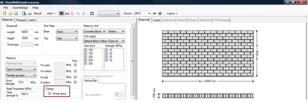 Figure 5‑15: Choosing to Smear Grout
With the ‘Smear grout’ check-box checked-on, designers can readily compare quick hand-calculations with the calculations obtained by the program. Since however, treating each cell individually provides a more accurate solution, MASS also allows users to check-off the ‘Smear grout’ check-box and obtain the more accurate solution. Both modes provide similar answers. However, using the discrete mode may provide an increase in capacity. For instance, in cases where the compression zone of the wall extends to several ungrouted cells in the web, as shown in Figure 5‑16: Compression Zone Extends One Cell into the Shear Wall Web‑.
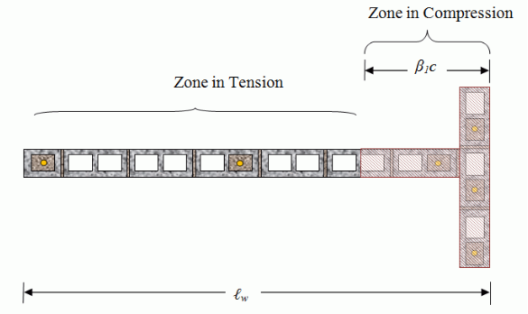 Figure 5‑16: Compression Zone Extends One Grouted Cell into the Shear Wall Web
In this case, in the web, using f’m,grouted rather than using f’m,eff, along with the actual web thickness t rather than the reduced web thickness teff, may provide a notable increase in the moment capacity of the shear wall.
![]() Note: This feature affects how the web is treated only. Checking-off the ‘Smear grout’ check-box has no impact on how partially grouted flanges are treated.
Note: This feature affects how the web is treated only. Checking-off the ‘Smear grout’ check-box has no impact on how partially grouted flanges are treated.
Because the compression zone does not move along the length of the wall cell-by-cell in the flanges, but rather, includes the entire effective length of a flange, whether the cells are treated discretely, or using smearing effects typically has a negligible effect on the capacity of the shear wall.
![]() Note: The opportunity to smear grout is only available for masonry unit types that allow for the presence of grout: hollow blocks and semi-solid blocks.
Note: The opportunity to smear grout is only available for masonry unit types that allow for the presence of grout: hollow blocks and semi-solid blocks.
In the remainder of the examples discussed in this page, the ‘Smear grout’ check-box is disabled to use discrete properties.
Constructability concerns
Constructability concerns are warnings of potential problems or details that require attention on the construction site based on the design selected. These constructability concerns are conveyed in the form of notes that are printed using output textbox, and in the shear wall assemblage drawings.
During the assemblage configuration step, a textbox provides users with constructability concerns that may arise based on the selected shear wall properties. A sample constructability concern is shown in Figure 5‑17: Sample Constructability Concern (Non-Modular Length). This constructability concern occurs when the designer selects an assemblage length that it is not an exact increment of the modular length (length of a masonry unit). Cutting units may increase the construction time, in addition to the extra tools and manpower required.
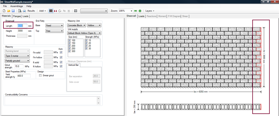 Figure 5‑17: Sample Constructability Concern (Non-Modular Length) for 6050 mm Length
The constructability concerns are not displayed in the textbox until at least the moment design step has been completed. Full constructability concerns are not provided until the shear design step is complete.
![]() Note: The success or failure of a design does not depend on the presence of constructability concerns, they are only warnings, and it is up to the designer to adjust the final design to guarantee that it is practical.
Note: The success or failure of a design does not depend on the presence of constructability concerns, they are only warnings, and it is up to the designer to adjust the final design to guarantee that it is practical.
At this time, users can proceed to the specifying the properties of flanges (if applicable), otherwise proceed to the loads input design step (Loads Input section).
Assemblage Configuration (Flanges)
Assemblage configuration is the first step in developing a shear wall design. This step allows users to enter the material properties of the shear wall. For the shear wall module only, the assemblage configuration step contains three tabs: the Materials tab, the Flanges tab and the Boundary Elements tab as shown in Figure 5‑1: Assemblage Configuration: Web, Flanges and Boundary Elements‑.
Within the flange tab, users can specify the masonry properties of the shear wall flanges. Flange properties must be fully specified. The program does not design for the flanges, as it assumes the walls have already been designed. That is, it does not iterate through possible flange configurations, it simply utilizes the properties specified by users and includes them in the shear wall capacity calculations. Only the web is truly designed by MASS.
For a shear wall with no flanges, the Flange tab can be ignored. This subsection deals with the masonry properties of the flanges only.
![]() Note: MASS does not design for flanges. MASS accounts for the presence of flanges but they must be fully specified.
Note: MASS does not design for flanges. MASS accounts for the presence of flanges but they must be fully specified.
To specify the properties of a shear wall flange:
- Click on the Flanges tab
- Choose flange style (none, T-shape, L-shape(up), L-shape(down), or custom)
- Enter the flange dimensions
- Select the type of masonry unit (concrete block, hollow, semi-solid, or solid)
- Choose the size and strength of the unit
- Provide the masonry properties
- Provide vertical steel properties
Flange Style
This version of the program allows the designer to specify boundary elements on both ends of the shear walls. These boundary elements are traditionally called flanges if they are intersecting masonry walls or boundary elements if they are masonry columns or pilaster units. Boundary elements can also be other materials like concrete or steel, however, this software package does not support other materials.
MASS supports the following boundary element or flange styles: none, T-shape, L-shape (up), L-shape (down), and custom. The left and right boundary element styles can be paired in any combination.
To specify flange properties, click on the Flanges tab, shown in Figure 5‑18: Choosing the Flange Style. To select a left flange style, click on the drop-down box marked ‘Style’, under the ‘Left Flange’ box, as shown in Figure 5‑18: Choosing the Flange Style. To select a right flange style, click on the drop-down box marked ‘Style’, under the ‘Right Flange’ box.
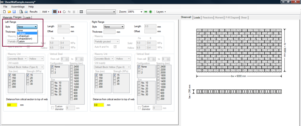 Figure 5‑18: Choosing the Flange Style
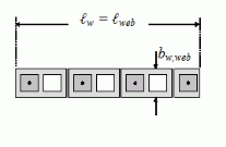
A shear wall can be constructed using any combination of the styles listed in Figure 5‑18: Choosing the Flange Style. The default flange style is none, in which case the shear wall only consists of the web, as shown in Figure 5‑19: Flange Style: None on Either Side of Web‑. A T-shaped right flange is a flange that is centered about the right side of the web. The flange is aligned to ensure that the block in the web aligns with the edge of the block in the flange as shown in Figure 5‑20: Choosing the Flange Style: T-Shape, Right Flange‑.
|
|
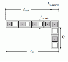
An L-shaped (up) right flange consists of a flange leg that placed above the web, on the right side. The bottom block in the flange is aligned with the bottom of the web, as shown in Figure 5‑21: Choosing the Flange Style: L-Shape (Up), Right Flange‑. An L-shaped (down) right flange consists of a flange leg that placed below the web, on the right side. The top block in the flange is aligned with the top of the web, as shown in Figure 5‑22: Choosing the Flange Style: L-Shape (Down), Right Flange‑.
|
|
|

For the current version of MASS, customized boundary elements are represented with a single rectangular box, and a single reinforcement area (if applicable).
Flange Dimensions
The shear wall flange dimensions that are required are dependent on the flange style chosen. If none is the flange style chosen, all flange input fields are disabled. For a T-shape flange style, users can select the length of the flange. The thickness of the flange is based on the masonry unit size selected. The T-shaped flange is automatically centered and aligned about the web of the shear wall, and the offset is automatically provided to users. For example, if 30 cm units are used in the web, and a left flange length of 2400 mm is entered, the program centers the left flange, resulting in a left offset value of 1055 mm.
 The resulting flange configuration is shown in Figure 5‑23: Entering a Left Flange Length.
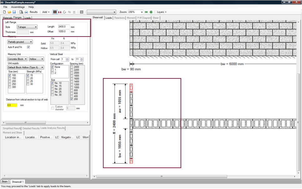 Figure 5‑23: Entering a Left Flange Length
Depending on the flange length provided users may wish to remove the need to cut units by adjusting the offset. For instance, for the shear wall shown in Figure 5‑24: Altering the Left Flange Offset, entering an offset of 1200 mm adjusts the location of the flange, and removes the red highlighting from the units, indicating that with this configuration, cutting the flange masonry units is not be required.
![]() Note: The flange length provided by users may not be the flange length that is used in the engineering calculations. For the engineering calculations, the program uses an effective flange length. This is discussed in greater detail in the Detailed Design section
Note: The flange length provided by users may not be the flange length that is used in the engineering calculations. For the engineering calculations, the program uses an effective flange length. This is discussed in greater detail in the Detailed Design section
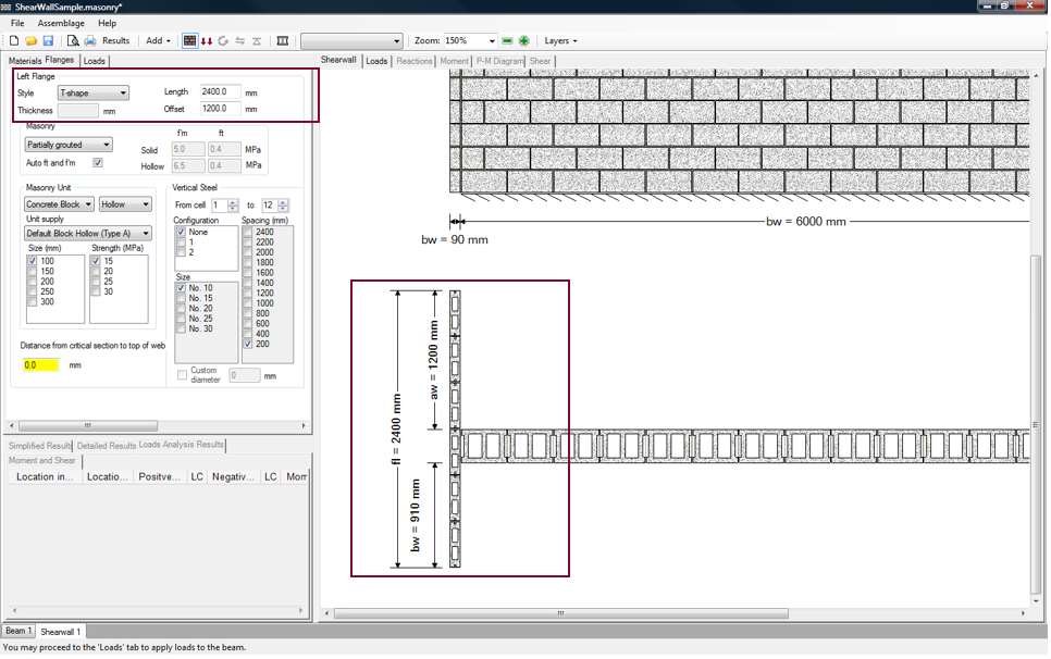 Figure 5‑24: Altering the Left Flange Offset
A right flange is specified in the same manner as the left flange. A shear wall with two T-shaped 2400 mm flanges (with offsets of 1200 mm) is illustrated in Figure 5‑25: Shear Wall with a Left T-Shaped Flange and a Right T-Shaped Flange‑. To view the shear wall drawing in full detail, the size of the top left window was reduced.
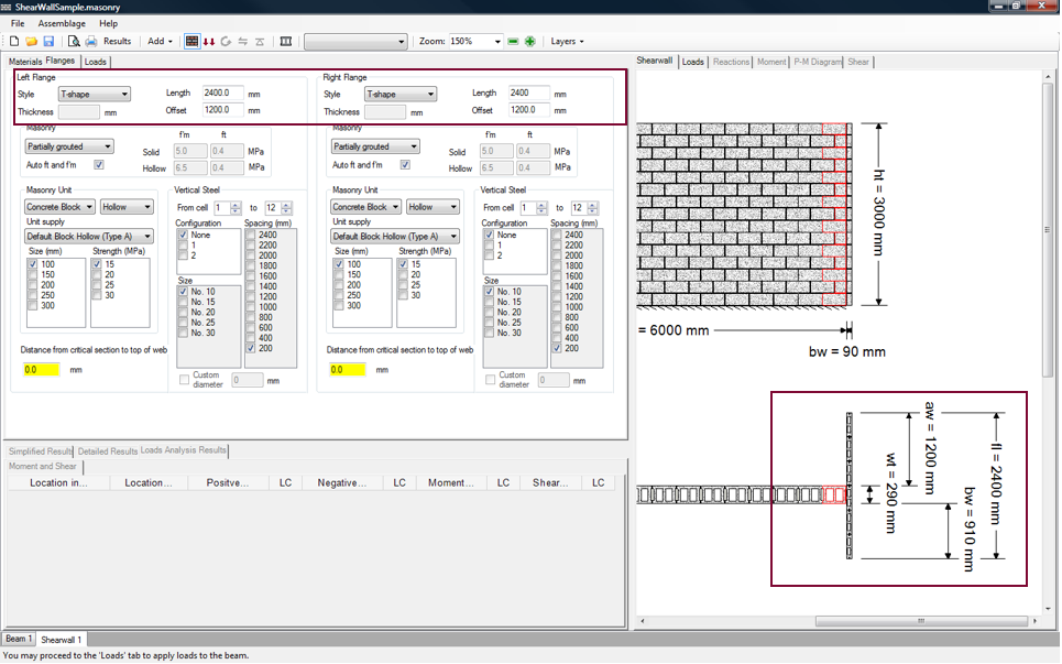 Figure 5‑25: Shear Wall with a Left T-Shaped Flange and a Right T-Shaped Flange
Notice that with the addition of the right flange, the masonry unit at the right end of the wall is outlined in red, indicating the design requires cut units. To avoid using cut units, adjust the length of the web by clicking on the Materials tab and entering a new length as shown in Figure 5‑26: Shear Wall (Modular) with a Left T-Shaped Flange and a Right T-Shaped Flange. To account for the mortar joint on either end of the wall add a length of 20 mm (assuming the web prior to the addition of flanges was modular in length):
5990mm+20mm = 6010 mm
The program allows for a 10 mm variance. A length of up to 6020 mm can be entered before the program highlights units in red.
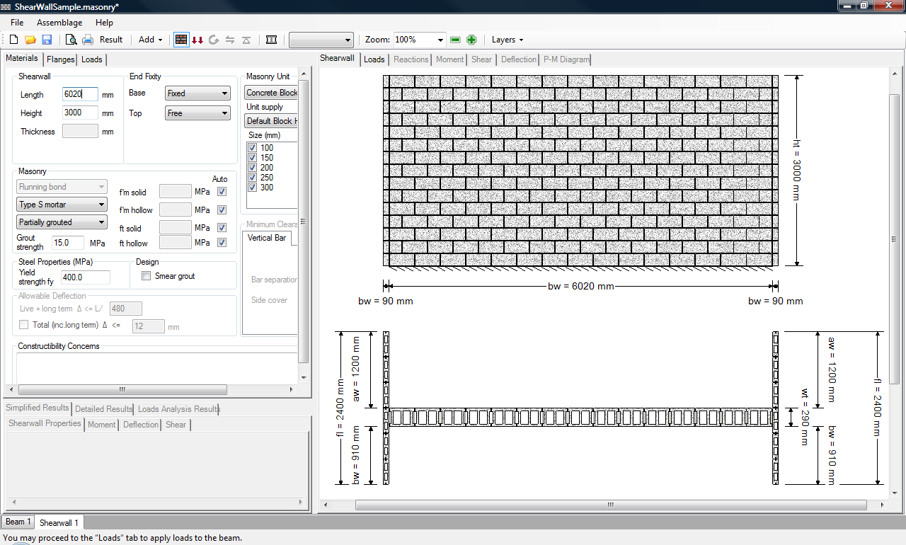 Figure 5‑26: Shear Wall (Modular) with a Left T-Shaped Flange and a Right T-Shaped Flange
For the L-shape (up or down) flange style, users can enter in only the length. The thickness of the flange is based on the masonry unit size selected. There is no offset to be entered, since the flange is automatically adjusted to align with the bottom of the web (for L-shape (up)) and the top of the web (for L-shape (down)), as is illustrated in Figure 5‑21: Choosing the Flange Style: L-Shape (Up), Right Flange‑ and Figure 5‑22: Choosing the Flange Style: L-Shape (Down), Right Flange‑, respectively.
For a custom boundary element, users are required to enter a thickness and a length. All dimensions in the program are entered in millimeters. Custom flanges are centered about the web (the offset textbox is disabled for custom flanges). A sample right flange with a length of 800 mm, and a thickness of 400 mm has been specified in Figure 5‑27: Entering the Dimensions of a Custom Flange.
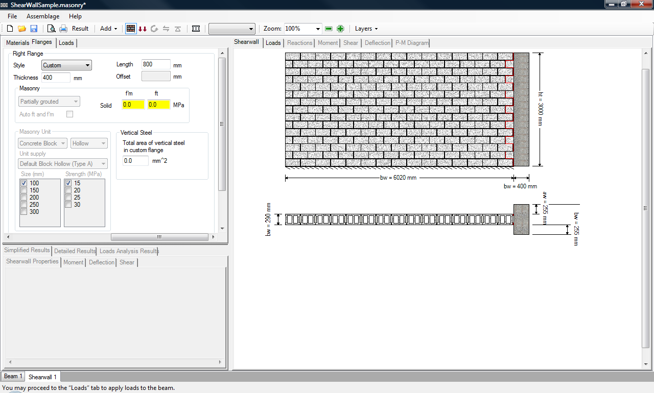 Figure 5‑27: Entering the Dimensions of a Custom Flange
For all flange styles, a minimum limit of 290 mm is placed on the length of the flange. This limit ensures that the flange is larger than then web thickness, t, no matter what masonry unit is chosen for the web (a 290 mm unit (30 cm nominal) being the largest of the default units).
Type of Masonry Unit
The type of masonry unit selected for each flange is selected in the same manner as for the shear wall web. The masonry unit type for each flange is selected independently of one another, and independently of the type of masonry unit type used within the shear wall web.
Shear wall flanges can be constructed using block types with the following solidity: hollow block, semi-solid, solid, half-high, half-block, and bond block. The default unit types for a flange placed to the left of the web are shown in Figure 5‑28: Choosing the Masonry Unit Type (Left Flange). The default unit types available for a flange placed to the right of the web are the same.
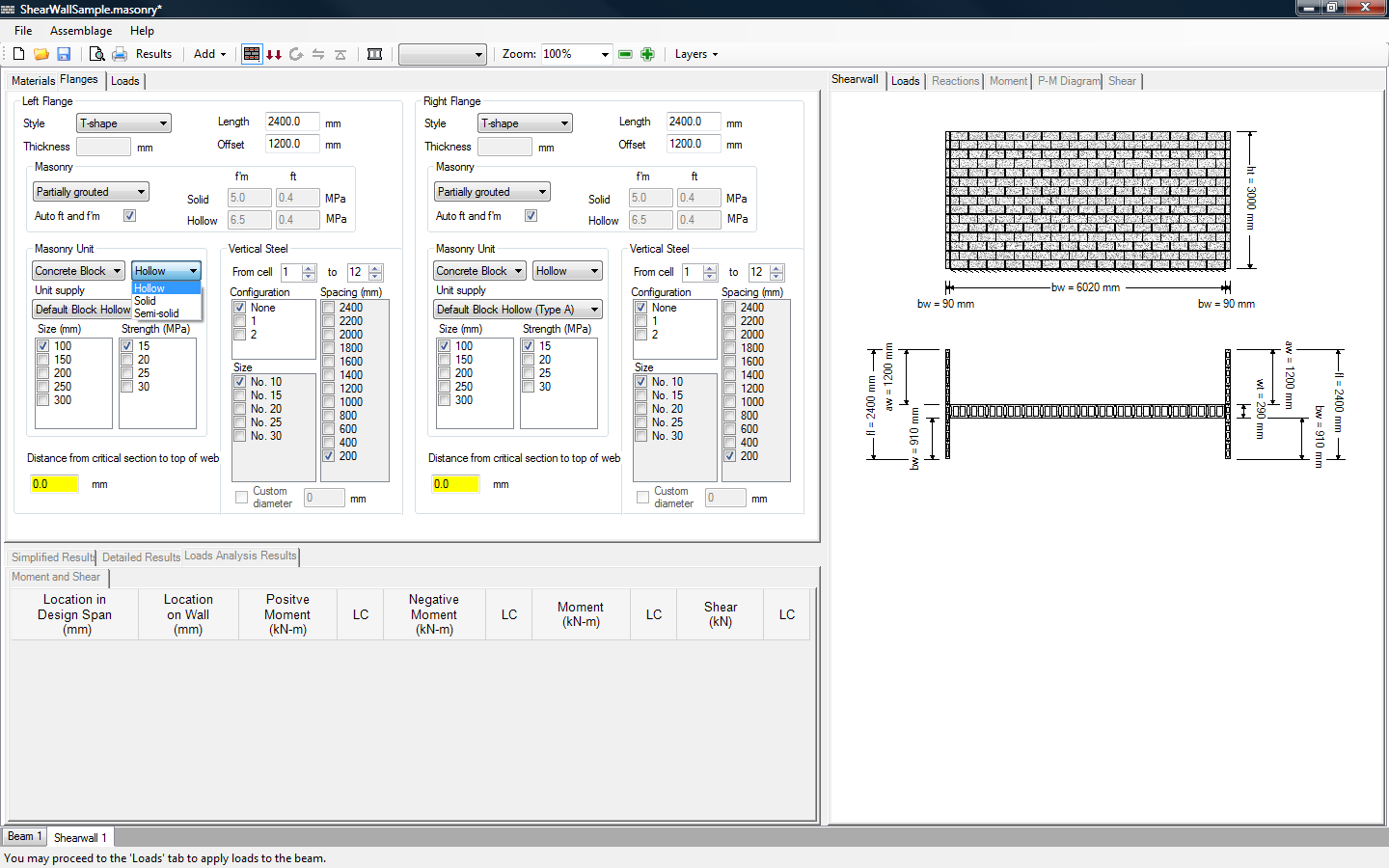 Figure 5‑28: Choosing the Masonry Unit Type (Left Flange)
![]() Note: T-Shaped flanges are typically constructed using mechanical fasteners. This is difficult to do when using solid units.
Note: T-Shaped flanges are typically constructed using mechanical fasteners. This is difficult to do when using solid units.
Users can also specify the unit supply of the masonry unit. This unit supply list contains default block types based on the solidity selected. For a block with a hollow solidity, the unit supplies available by default are shown in Figure 5‑29: Choosing the Unit Supply (Left Flange).
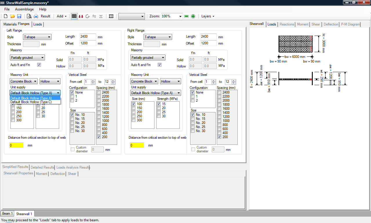 Figure 5‑29: Choosing the Unit Supply (Left Flange)
The unit supply lists also includes customized units if they have been entered into the masonry unit database (refer to the masonry unit database section).
Unit Size and Strength
The type of masonry unit selected for each flange is selected in a similar manner as for the shear wall web. The important difference is that only one masonry unit size and masonry unit strength can be selected at a time. This is because MASS requires that flanges be fully specified, assuming the flanges are walls that have been successfully designed at a previous time.
In the program, the size of the unit refers to the nominal thickness (t + 10mm mortar joint) of the masonry unit. The strength selection pertains to the compressive strength of the unit, f’m.
The default concrete block sizes available include 10, 15, 20, 25, and 30 cm units. The default block strengths include 15, 20, 25, and 30 MPa. By default, the program selects a masonry unit with the smallest size and the lowest strength, as shown in Figure 5‑28: Choosing the Masonry Unit Type (Left Flange)‑. The unit strengths available for design depends on the supplier, however, the values provided by in the program by default are the typical values used in masonry construction. Other strengths are possible and are accommodated by the program through the masonry unit database (refer to the masonry unit database section). MASS does not support using brick units for flanges for shear wall design.
A shear wall with flanges designed using 20 MPa, 20 cm units is shown in Figure 5‑30: Choosing the Size and Strength of the Masonry Units in Left and Right Flange‑. These flange sizes and strength settings are used throughout the rest of this chapter.
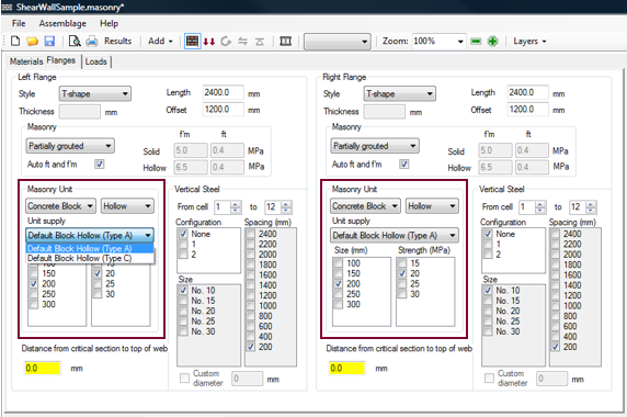 Figure 5‑30: Choosing the Size and Strength of the Masonry Units in Left and Right Flange
![]() Note: The size and strength of the unit for each flange is selected independently of one another and independently of the type of masonry used within the shear wall web. For example, a 20 cm unit can be used in the web, and a 30 cm unit can be used in the right flange.
Note: The size and strength of the unit for each flange is selected independently of one another and independently of the type of masonry used within the shear wall web. For example, a 20 cm unit can be used in the web, and a 30 cm unit can be used in the right flange.
End Fixity
The end fixities of the flanges are assumed to be the same as the end fixity of the web.
Masonry Properties
The masonry properties (bond pattern, mortar type, grout strength, and yield strength) selected in the Assemblage Configuration (Web) section are also applicable to the flanges, and cannot be specified independently of the web. Refer to the ‘Masonry Properties’ section for instructions on changing these properties.
The grouting patterns of the flanges, as well as the compressive and tensile strengths of the flanges can be selected independently of the web.
The grouting pattern in the left flange is changed using drop-down box shown in Figure 5‑31: Choosing the Grouting Pattern in Left Flange. The grouting pattern in the right flange is changed in a similar manner.
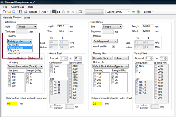 Figure 5‑31: Choosing the Grouting Pattern in Left Flange
The choices for the grouting pattern of each flange depend on the masonry unit type selected by users. For hollow concrete blocks, the grouting patterns permitted are: not grouted, partially grouted, and fully grouted. For semi-solid concrete blocks, the grouting patterns permitted are: not grouted, partially grouted, and fully grouted. For solid concrete blocks, the grouting patter permitted is: not grouted. If not grouted is selected, the ability to place vertical steel is disabled for all masonry unit type. If partially grouted is selected, the grouting pattern is governed by vertical steel placement.
The compressive and tensile strength values of an assemblage are calculated automatically within the program using Table 3, Table 4 and Table 5 in CSA S304 and depend on the masonry unit type selected and the grouting conditions. Upon the completion of the moment design step, (or as soon as users select only one masonry unit size and strength), the compressive and tensile strength used in the design are displayed in the textbox.
To override a compressive strength value, uncheck the ‘Auto’ box and enter the compressive and tensile strength values into the corresponding textbox. For example, for a hollow wall, fully grouted, users are permitted to enter prism test values for f’m,solid, f’m,hollow, ft,grouted, and ft,hollow. Uncheck the ‘Auto’ check-box next to each value. Then enter appropriate compressive strength and tensile strength values, as shown in Figure 5‑32: User Override of Compressive and Tensile Strengths (Left Flange). Press Enter on the keyboard.
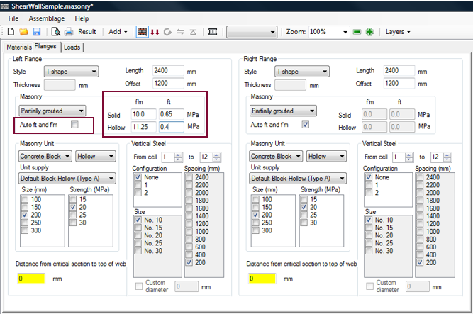 Figure 5‑32: User Override of Compressive and Tensile Strengths (Left Flange)
For custom flanges, the compressive and tensile strength of the flange must be provided by users. Figure 5‑33: Entering Compressive and Tensile Strengths of Custom Flanges provides a custom flange, with a compressive strength of 10 MPa, and a tensile strength of 0.65 MPa.
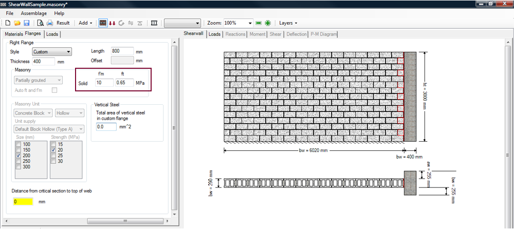 Figure 5‑33: Entering Compressive and Tensile Strengths of Custom Flanges
It is common to perform prism tests to gain additional capacity. Because masonry typically fail under compression, designers primarily perform prism tests to determine compressive strength values. However, if users check-off the ‘Auto’ box, the program requires users to provide both the compressive and tensile strengths. It is acceptable to use compressive strength values determined using prism tests, but enter tensile strength values using Table 5 from CSA S304-14.
The compressive and tensile strength values shown in Figure 5‑32: User Override of Compressive and Tensile Strengths (Left Flange) are used for illustrative purposes only, and are not based on actually prism tests. The remainder of this chapter utilizes compressive and tensile strength values automatically determined by the program.
Vertical Steel
The steel property (yield strength) selected in Steel Properties section is also applicable to any reinforcement bars placed in the flanges, and cannot be specified independently of the web. Refer to the ‘Steel Properties’ section for instructions on changing this property. The number of bars per cell, the bar size, and the spacing of the vertical reinforcement can be selected independently of the web.
Flange properties must be fully specified. Thus, similarly to the masonry properties, only one check-box can be checked-on for the number of bars per cell, bar size, and spacing of a specific cell.
![]() Note: All other flange properties (the style, dimensions, unit type, size, strength, grouting pattern and compressive and tensile strengths) should be entered prior to specifying the vertical steel configuration in the flanges. Changing these flange properties reloads the number of bars per cell to zero (default).
Note: All other flange properties (the style, dimensions, unit type, size, strength, grouting pattern and compressive and tensile strengths) should be entered prior to specifying the vertical steel configuration in the flanges. Changing these flange properties reloads the number of bars per cell to zero (default).
To specify the vertical reinforcement in a T-shape or L-shape flange:
- Choose the cell range
- Select the number of bars per cell
- Select the bar size
- Select the bar spacing
MASS numbers the cells in a flange from the bottom to the top, as shown in Figure 5‑34: Flange Cell Count.
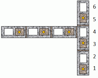 Figure 5‑34: Flange Cell Count
The cell range, by default, includes the entire length of the flange. To change the cell range, use the up or down arrows, or type the cell number into the textbox. This is shown in Figure 5‑35: Cell Range for Entire Length Flange (Left Flange).
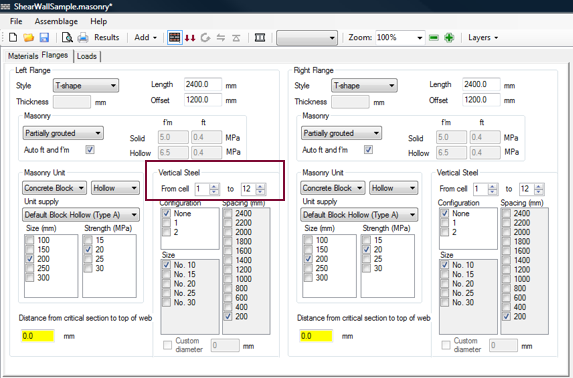 Figure 5‑35: Cell Range for Entire Length Flange (Left Flange)
To alter the property of a specific cell (for example, cell 2), enter the cell number in the first textbox and the second textbox, as shown in Figure 5‑36: Cell Range for a Specific Cell (Left Flange).
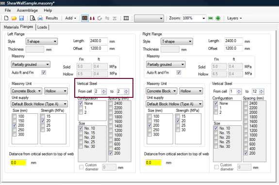 Figure 5‑36: Cell Range for a Specific Cell (Left Flange)
![]() Note: The vertical steel configuration for a new cell range overrides a previously entered vertical steel configuration if the new cell range overlaps with a previously specified cell range. In other words when a new vertical steel configuration is entered for a cell range, this new configuration governs over that previously entered for that cell range. The original vertical steel configuration still applies for any cells outside this range.
Note: The vertical steel configuration for a new cell range overrides a previously entered vertical steel configuration if the new cell range overlaps with a previously specified cell range. In other words when a new vertical steel configuration is entered for a cell range, this new configuration governs over that previously entered for that cell range. The original vertical steel configuration still applies for any cells outside this range.
By default, the number of bars per cell is ‘None’ for the entire length of a flange. The ‘Size’ check-boxes and the ‘Strength’ check-boxes in this case are grey to indicate they are disabled. To activate the ‘Size’ or ‘Strength’ check-boxes for a particular cell range chosen users must select either ‘1’ or ‘2’ bars per cell, rather than ‘None’. The number of bars per cell can be selected under the ‘Configuration’ heading.
To select 1 bar per cell, click on the ‘1’ check-box. To select the bar size desired for the particular cell range chosen, check-on the desired bar size check-box. To select the bar spacing desired for the particular cell range chosen, check-on the desired bar size check-box. For example, click on the ‘No. 20’ check-box to place No. 20 bars along the length of the left flange, at a spacing of 600 mm, as shown in Figure 5‑37: Selecting the Vertical Reinforcement in the Flanges. Notice, the same reinforcement arrangement has been added to the right flange.
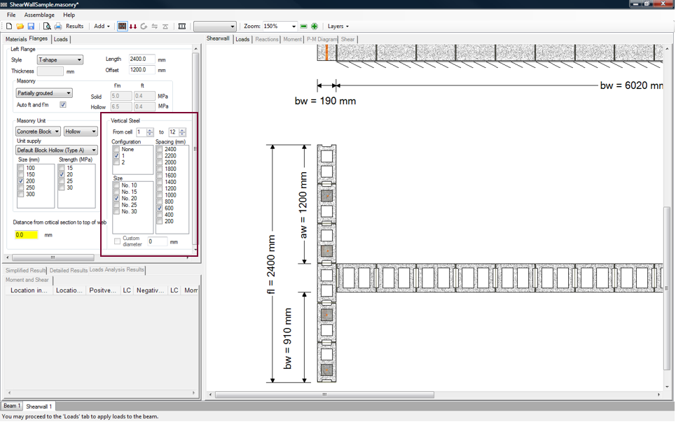 Figure 5‑37: Selecting the Vertical Reinforcement in the Flanges
![]() Note: The program does not allow users to reinforce a flange without providing reinforcement within the web. This is enforced through minimum reinforcement required in the web.
Note: The program does not allow users to reinforce a flange without providing reinforcement within the web. This is enforced through minimum reinforcement required in the web.
If there are two bars placed in one cell, MASS requires that the bars be of the same size. It is not possible for users to select the specific size of the two bars independently. The location of the vertical reinforcement bars within the cells cannot be altered by the user: the bars are automatically placed in the centre of the cells.
If users select one bar per cell, the bar is automatically placed at the centre of the cell. If users select two bars per cell, the bars are placed at the centre of the cell, with a bar separation 25 mm (A371-14: 8.2.5.4.9.1).
![]() Note: Flange properties must be fully specified by the designer. It is up to the designer to ensure that cover and spacing requirements of the vertical steel in the flanges is met.
Note: Flange properties must be fully specified by the designer. It is up to the designer to ensure that cover and spacing requirements of the vertical steel in the flanges is met.
If there are two bars placed in one cell, MASS requires that the bars be of the same size. It is not possible for users to select the specific size of the two bars independently.
For a bar size not specified in the check-box list, enter the bar diameter into the neighbouring textbox and press Enter. The ‘Custom diameter’ check-box then checks-on automatically. A custom diameter of 22.225 mm is specified in Figure 5‑38: Entering a Custom Bar Diameter‑.
This diameter specified as 22.2225 in millimeters is equivalent to 0.876=7/8 inches. Following the American reinforcement bar sizes, this is the diameter of a No. 7 bar.
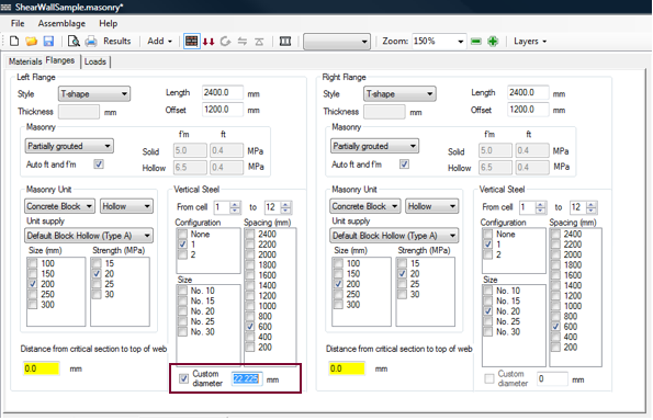 Figure 5‑38: Entering a Custom Bar Diameter
![]() Note: Imperial bar sizes must be entered in metric units in the custom diameter textbox.
Note: Imperial bar sizes must be entered in metric units in the custom diameter textbox.
The custom diameter size is limited to a 25 mm diameter bar. This feature was introduced to allow for imperial reinforcement bar sizes, which are used in some locations in Canada, particularly those in close proximity with the United States border.
![]() Note: MASS provides a lot of versatility and allows for users to change the vertical steel configuration for each cell. Because of this, it is possible for users to specify some rather exotic or difficult to construct flanges. For instance, a designer could specify a flange with a varying number of bars per cell, and varying bar sizes all within one flange. In most cases however, flanges with uniformly distributed vertical steel tend to perform better, are easier to construct and design, and are thus recommended.
Note: MASS provides a lot of versatility and allows for users to change the vertical steel configuration for each cell. Because of this, it is possible for users to specify some rather exotic or difficult to construct flanges. For instance, a designer could specify a flange with a varying number of bars per cell, and varying bar sizes all within one flange. In most cases however, flanges with uniformly distributed vertical steel tend to perform better, are easier to construct and design, and are thus recommended.
The ability to place vertical steel is disabled if the grouting pattern selected is not grouted, because grout is required to anchor vertical steel.
To specify the vertical reinforcement in a custom flange, enter the total area of vertical steel used within the boundary element. The vertical steel is placed at the centre of the boundary element, as shown in Figure 5‑39: Entering Vertical Steel in a Custom Flange‑.
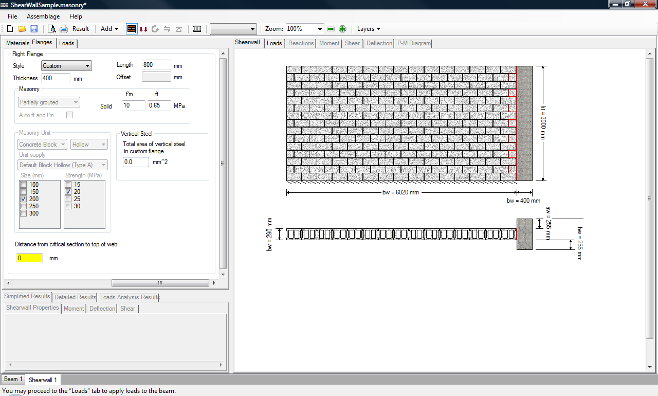 Figure 5‑39: Entering Vertical Steel in a Custom Flange
Horizontal steel properties (joint reinforcement or bond beam reinforcement) can only be altered once the shear design step is completed.
Distance from Critical Section
In addition to fully specifying the properties of the flange(s), the designer must also specify the distance from the critical section (where the moment has the largest value) of the shear wall being designed to the top of the web (Figure 5‑40: Entering the Distance from Critical Section to Top of Web‑). The distance from the critical section to top of web depends on the height of the wall and the fixity conditions on the wall. For a single wall with Fixed-Free conditions, the distance from the critical section to the top of the web is equal to the height of the shear wall, as shown in Figure 5‑41: Distance from Critical Section to Top of Web‑.
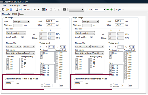 Figure 5‑40: Entering the Distance from Critical Section to Top of Web
This is because for the load case and end fixities shown in Figure 5 41 the critical section occurs at the bottom of the shear wall.
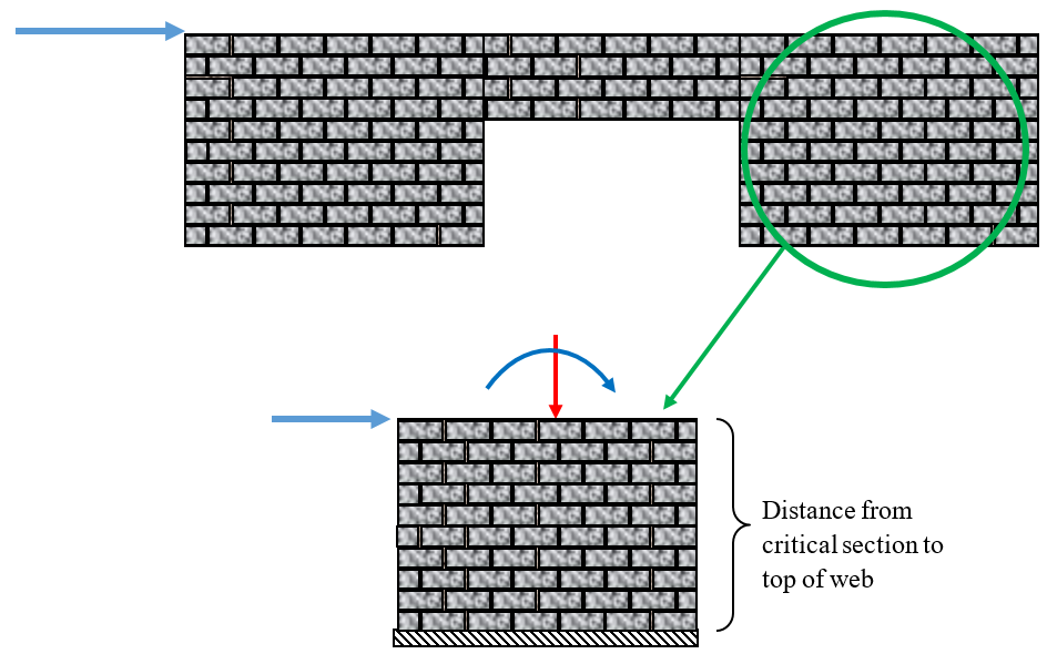 Figure 5‑41: Distance from Critical Section to Top of Web
However, if the shear wall is part of a larger structure, the distance from the critical section to the top of the web includes the larger structure above the critical section, as shown in Figure 5‑42: Distance from Critical Section to Top of Web in a Multi-Storey Structure‑.
 Figure 5‑42: Distance from Critical Section to Top of Web in a Multi-Storey Structure
Click here for additional information on designing multi-story loadbearing masonry buildings.
![]() Note: The distance from the critical section to the top of the web is used to determine the effective flange length(s), as required by CSA S304-14: 7.6.1 and 10.6.2.
Note: The distance from the critical section to the top of the web is used to determine the effective flange length(s), as required by CSA S304-14: 7.6.1 and 10.6.2.
![]() Note: If users enters zero, or leaves the default zero value in the distance from the critical section to top of web textbox, the program is not able to use the effects of the flanges, resulting in an effective length of the flange that is equal only to the width of the shear wall web.
Note: If users enters zero, or leaves the default zero value in the distance from the critical section to top of web textbox, the program is not able to use the effects of the flanges, resulting in an effective length of the flange that is equal only to the width of the shear wall web.
At this time, users can proceed to the loads input design step. Be aware however, that during this design step the assemblage properties previously selected cannot be altered.
Assemblage Configuration (Boundary Elements)
Assemblage configuration is the first step in developing a shear wall design. This step allows users to enter the material properties of the shear wall. For the shear wall module only, the assemblage configuration step contains three tabs: the Materials tab, the Flanges tab and the Boundary Elements tab as shown in Figure 5‑1: Assemblage Configuration: Web, Flanges and Boundary Elements‑.
Within the boundary element tab, users can specify the masonry properties of the shear wall boundary elements. Just like flanges, boundary element properties must be fully specified. The program does not design for the boundary elements, as it assumes the walls have already been designed. That is, it does not iterate through possible boundary elements configurations, it simply utilizes the properties specified by users and includes them in the shear wall capacity calculations. Only the web is truly designed by MASS.
For a shear wall with no boundary elements, the Boundary Elements tab can be ignored. This subsection deals with the masonry properties of the boundary elements only.
![]() Note: MASS does not design for boundary elements. MASS accounts for the presence of boundary elements but they must be fully specified.
Note: MASS does not design for boundary elements. MASS accounts for the presence of boundary elements but they must be fully specified.
To specify the properties of a shear wall flange:
- Click on the Boundary Elements tab
- Choose flange style (none, or boundary element unit)
- Enter the boundary element dimensions
- Enter the boundary element face shell thickness
- Provide the masonry properties
- Provide vertical steel properties
Boundary Element Style
This version of the program allows the designer to specify boundary elements on both ends of the shear walls. These boundary elements are traditionally called boundary elements if they are masonry columns or pilaster units. Boundary elements can also be other materials like concrete or steel, however, this software package does not support other materials.
MASS supports the following boundary element styles: none, and boundary element unit. The left and right boundary element styles can be paired in any combination.
To specify boundary element properties, click on the Boundary Elements tab, shown in Figure 5‑43: Choosing the Boundary Element Style. To select a left boundary element style, click on the drop-down box marked ‘Style’, under the ‘Left Boundary Element’ box, as shown in Figure 5‑43: Choosing the Boundary Element Style. To select a right boundary element style, click on the drop-down box marked ‘Style’, under the ‘Right Boundary Element’ box, if it is not the same as the Left Boundary Element.
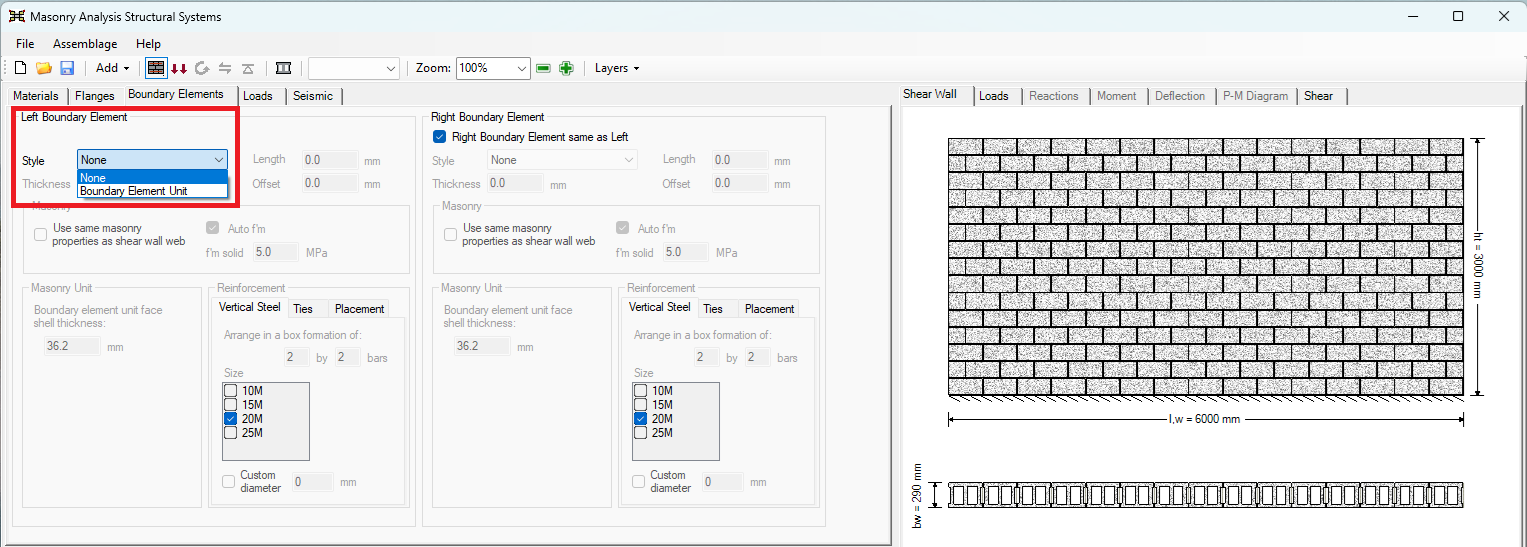 Figure 5‑43: Choosing the Boundary Element Style
A shear wall can be constructed using any combination of the styles listed in Figure 5‑43: Choosing the Boundary Element Style. The default flange style is none, in which case the shear wall only consists of the web.
Boundary Element Dimensions
The shear wall boundary element dimensions that are required are the length and the thickness. If none is the boundary element style chosen, all boundary element input fields are disabled. The default thickness of the boundary element is 390mm. The default offset is 0mm, which means that the boundary element is flush with the wall on one side. The maximum offset is the thickness of the boundary element subtracted by the thickness of the unit. For a default boundary element thickness of 390 and a default unit thickness of 290, the maximum offset is 100mm. This implies that the boundary element is flush with the other side of the wall. The resulting boundary element configuration is shown in Figure 5‑44: Entering a Left Boundary Element Length.
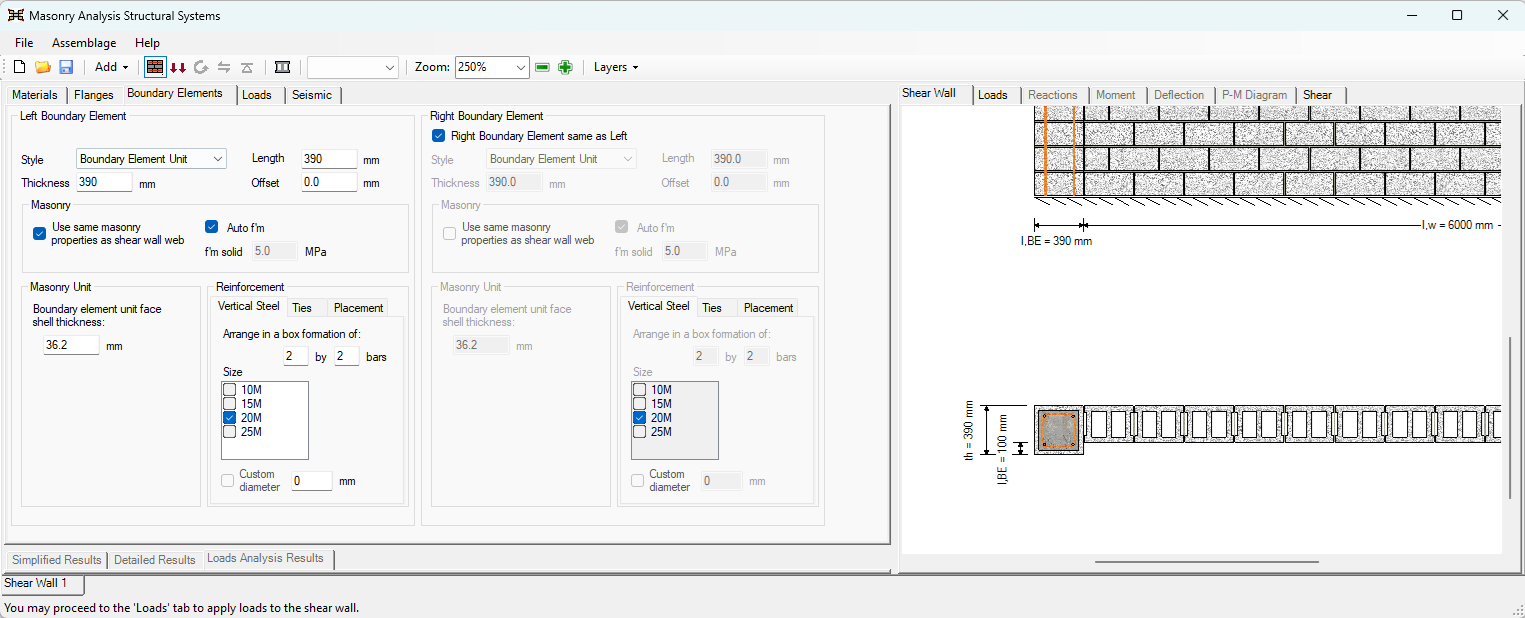 Figure 5‑44: Entering a Left Boundary Element Length
Masonry Properties
In the boundary elements tab, the user has the option to select the face shell thickness of the masonry unit. In addition to this the user can specify if the f’m solid is the same as the rest of the wall or different than what was specified in the Materials tab.
End Fixity
The end fixities of the flanges are assumed to be the same as the end fixity of the web.
Vertical Steel
The steel property (yield strength) selected in Steel Properties section is also applicable to any reinforcement bars placed in the boundary elements, and cannot be specified independently of the web. Refer to the ‘Steel Properties’ section for instructions on changing this property. The number of bars per boundary element, the bar size, and the formation in a box can be selected independently of the web.
Boundary element properties must be fully specified. Thus, only one check-box can be checked-on for the bar size, and tie size
To specify the vertical reinforcement in a boundary element:
- Enter the box formation in which the bars will be arranged by
- Select the bar size
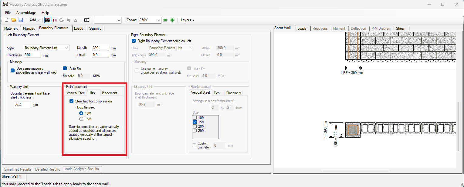
- Select if the bars are tied in compression
The vertical steel selections can be seen in Figure 5‑45: Vertical Steel Options
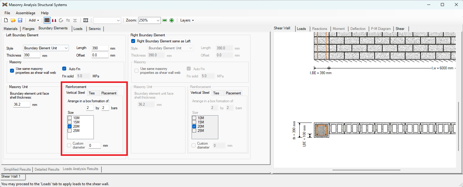 Figure 5‑45: Vertical Steel Options
The tie options can be seen in Figure 5‑46: Tie Options
Loads Input
Loads input is the second step in developing a shear wall design. This step allows users to enter the loads that are applied to the assemblage. Loads are applied in a similar manner for all assemblage types.
- Click on the Loads Input button
 , or on the Loads tab
 - Choose the importance category (low, normal, high, post-disaster)
- Click on Add Load
- Enter in load properties (type, distribution, unfactored magnitude, and units)
Loads Input
There are two ways to begin the loads input design step: click on the Loads Input button or the Loads tab. Notice that when performing the loads input design step, the Loads Input button is outlined in blue, as shown in Figure 5‑47: Loads Input Design Step‑. Upon moving into the load inputs design step, the program automatically displays to the load drawing in the Loads tab in the right window.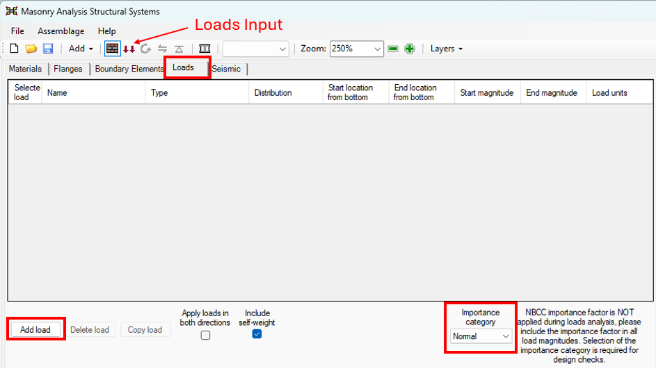
Figure 5‑47: Loads Input Design Step
Notice that when performing the loads input design step, the Loads Input button is outlined in blue. During this design step, the material and flange properties should not be changed.
Importance Category
The importance category is selected using the drop-down box under the heading ‘Importance category’, shown in Figure 5‑47: Loads Input Design Step‑. The importance category specifies the importance of a building, which is determined based on the hazard a building failure could pose. For more information, refer to Importance Category section.
Load Properties
To add a load, click on the Add Load button shown in Figure 5‑47: Loads Input Design Step‑. For more information on adding, copying, and deleting loads, refer to the Loads Input section.
The program allows for the selection of the following loads for the shear wall assemblage: dead, live, snow, wind, lateral earth, earthquake, storage, controlled fluid, and vertical soil. These can be selected using the drop-down box found under the ‘Type’ column.
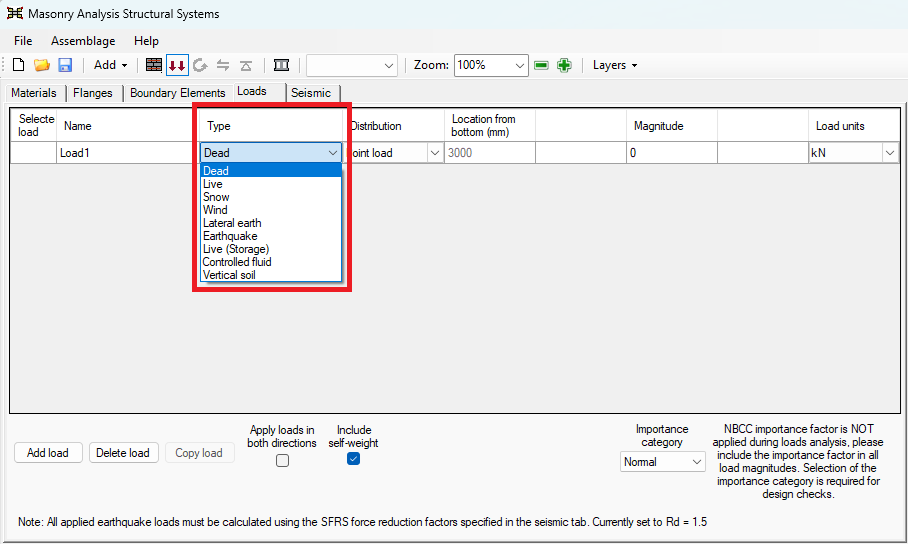 Figure 5‑48: Choosing Load Types
Similarly to choosing a load type, users can choose the load distribution using the drop-down box found under the ‘Distribution’ column. Load distributions that can be applied to a shear wall include: point loads, axial loads, and moments.
![]() Note: MASS does not allow for eccentric loading in the vertical direction, that is, the centre of loading in the y-direction is considered to be in the centre of the wall section. Instead, eccentricity of the vertical loads can be taken into account indirectly, by applying a moment to the shear wall.
Note: MASS does not allow for eccentric loading in the vertical direction, that is, the centre of loading in the y-direction is considered to be in the centre of the wall section. Instead, eccentricity of the vertical loads can be taken into account indirectly, by applying a moment to the shear wall.
The loads input design step in the shear wall module is more restrictive than in the beam module or the out-of-plane module. For the shear wall module, the location of the load cannot be specified by users. In all cases the load is applied at the height of the shear wall, as shown in Figure 5‑49: Point Load, Axial Load and Moment on a Shear Wall‑.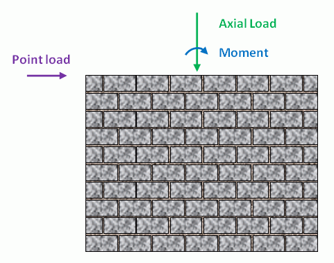
Figure 5‑49: Point Load, Axial Load and Moment on a Shear Wall
The unfactored magnitude of the selected load is entered in the textbox, under the ‘Magnitude’ column. Negative axial loads (uplift) are permitted. Negative point loads (in east-west direction) or negative moments (in the counter-clockwise direction) however, cannot be applied. To design the wall in the reverse direction click on the ‘Apply loads in both directions’ check-box shown in Figure 5‑49: Applying Loads in Both Directions‑.
A shear wall, experiencing an unfactored dead shear (point) load of 500 kN, an unfactored axial dead load of 1500 kN, an unfactored axial live load of 200 kN, and an applied unfactored dead moment of 100 kN-m is illustrated in Figure 5‑50: Entering Several Load Magnitudes. Notice the loads are applied at the height of the shear wall.
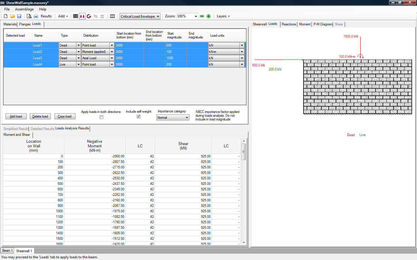 Figure 5‑50: Entering Several Load Magnitudes
![]() Note: According to MASS sign convention, a left-to-right load is considered a positive load, as is a downward axial load. A moment applied in the clockwise direction is considered a positive moment.
Note: According to MASS sign convention, a left-to-right load is considered a positive load, as is a downward axial load. A moment applied in the clockwise direction is considered a positive moment.
The units of the load can be specified using one of the following units (kN/m, N/m, lb/ft, or kip/ft) simply by selecting the drop-down box under the ‘Load units’ column.
Unlike the beam and out-of-plane modules, the percentage of the load sustained is not included in the loads input design step. This is because MASS does not perform any deflection calculations for shear walls.
A specific applied load can be viewed under the Loads tab by clicking on ‘Selected Load’ box of that particular load. Multiple loads can be viewed by holding down Shift key, and selecting the loads to be displayed. Figure 5‑53: Entering Several Load Magnitudes‑ shows four selected applied loads that are displayed in the Loads tab. The applied loads that are being displayed are outlined in blue in the input table. In the loads drawing, the load colours correspond to the load types (refer to the Drawings section).
Critical Load Envelope
With each new load added, the program uses the Importance category selected in order determine the corresponding factored load combinations based on CSA S304-14: 4.2.2. In order view all applicable load combinations click on the Critical Load Envelope drop-down box, as shown in Figure 5‑51: Choosing a Load Combination.
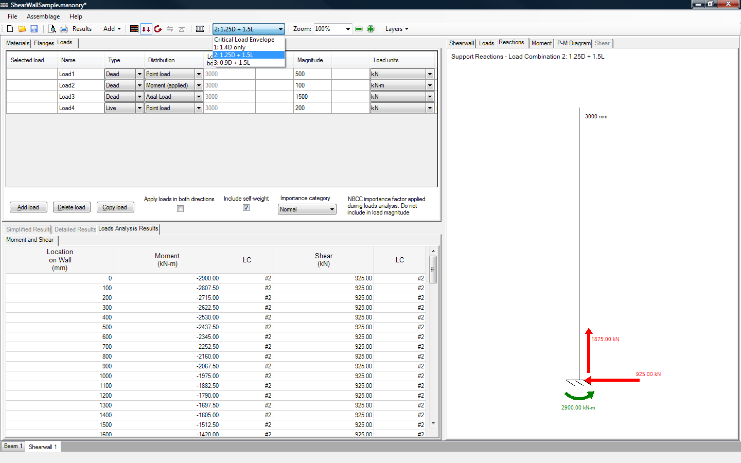 Figure 5‑51: Choosing a Load Combination
Notice that the drawings under the Reactions, Moment, and Shear tabs, reflect the selected load combination.
Self-Weight
To the left of the ‘Importance category’ drop-down box is the ‘Include self-weight’ check-box. The self-weight is included in the load calculations by default. To exclude the self-weight of the assemblage check-off the ‘Include self-weight’ check-box, as shown in Figure 5‑52: Including the Self-Weight.
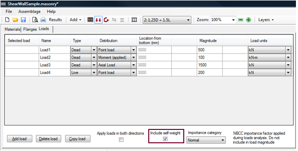 Figure 5‑52: Including the Self-Weight
The self-weight of a wall depends on the masonry unit size, the unit density, and the grouting condition. It is therefore likely that the self-weight of the wall will change during the moment design step, while the program iterates through all the selected masonry and vertical steel properties. In reinforced, partially grouted walls, for example, the grout is only placed at the location of vertical reinforcement. As a result, the self-weight of the wall will be affected each time the spacing of the reinforcement is changed. Notice, a partially grouted wall with a vertical bar spacing of 1200 mm contains less grout then the same partially grouted wall with a vertical bar spacing of 800 mm.
The self-weight of the wall may also change during the shear design step, while the program iterates through all the possible bond beam configurations. In reinforced, partially grouted walls, for example, the grout is placed at the location of vertical reinforcement and the location of a bond beam. As a result, the self-weight of the wall will be affected each time the spacing of the reinforcement is changed. Notice, a partially grouted wall with a bond beam spacing of 1200 mm contains less grout then the same partially grouted wall with a bond beam spacing of 800 mm.
The program calculates an initial self-weight based on the masonry properties selected in the assemblage configuration design step. The self-weight is included as a dead load.
In order to include the effect of grout on the self-weight of the wall, the grout density is required. In MASS, a grout density of 2350 kg/m3 is assumed.
For more details on calculating the self-weight of shear walls, refer to Self-Weight section.
Apply Load in Both Directions
To design the wall in the reverse direction check-on the ‘Apply loads in both directions’ check-box shown in Figure 5‑53: Applying Loads in Both Directions‑. Notice that by default, the shear wall is not designed in both directions.
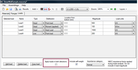 Figure 5‑53: Applying Loads in Both Directions
For this version of the program, the unfactored magnitude of the selected load that is entered in the textbox (under the ‘Magnitude’ column) must result in a positive moment. That is, negative axial loads (uplift) are permitted, however, negative point loads (in east-west direction) or negative moments (in the counter-clockwise direction) cannot be applied (refer to Figure 5‑49: Point Load, Axial Load and Moment on a Shear Wall). Users are permitted, however, to design the wall in both directions. In order apply the loads in both directions, the shear wall is mirrored about the vertical axis, as shown in Figure 5‑54: Original Shear Wall Configuration‑ and Figure 5‑55: Reverse Loading Shear Wall Configuration.
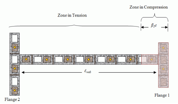 Figure 5‑54: Original Shear Wall Configuration
The right side of the wall is typically the side in compression
, while the left side of the shear wall is typically in tension. The flange on the right side of the wall is deemed flange 1 and the flange on the left side is deemed flange 2.
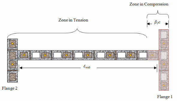 Figure 5‑55: Reverse Loading Shear Wall Configuration
Applying the loads in both directions is also permitted in the absence of any flange, particularly if the shear wall web configuration is not symmetric about the vertical axis. This feature does not have an impact on the design if the shear wall is symmetric.
Upon the completion of the loads input design step, users can proceed to the moment design step.
Seismic Design
If an earthquake load is specified during the loads input design step, users are required to complete the Seismic Design tab before proceeding with the design. The Seismic Design tab is shown in Figure 5-56: Seismic Design Tab:
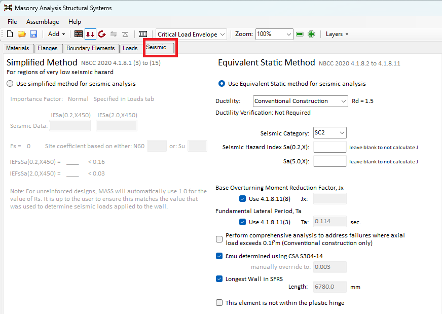
Figure 5‑56: Seismic Design Tab
![]() Note: The importance category selected during the loads input design step affects several seismic checks performed by MASS. Users should ensure that the correct importance category is selected before proceeding with a seismic design.
Note: The importance category selected during the loads input design step affects several seismic checks performed by MASS. Users should ensure that the correct importance category is selected before proceeding with a seismic design.
For regions of very low seismic hazard, users may select the simplified method of seismic analysis. When this option is selected, MASS requires the inputs shown in Figure 5-57: Simplified Method of Seismic Analysis. Based on the values entered, MASS determines whether the simplified method of analysis is permitted for the wall being designed. Where the simplified method is applicable, users should complete their analysis in accordance with NBCC 2020: 4.1.8.1(3) to 4.1.8.1(15).
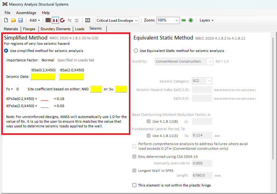 Figure 5‑57: Simplified Method of Seismic Analysis
By default, the Equivalent Static Method is selected. When this seismic analysis method is used, several additional inputs must be specified. The first input is the ductility category. Users can select one of the following options: None (Rd = 1.0), Conventional Construction (default, Rd = 1.5), Moderately Ductile (Rd = 2.0) and Ductile (Rd = 3.0). This is shown in Figure 5-58: Ductility Selection
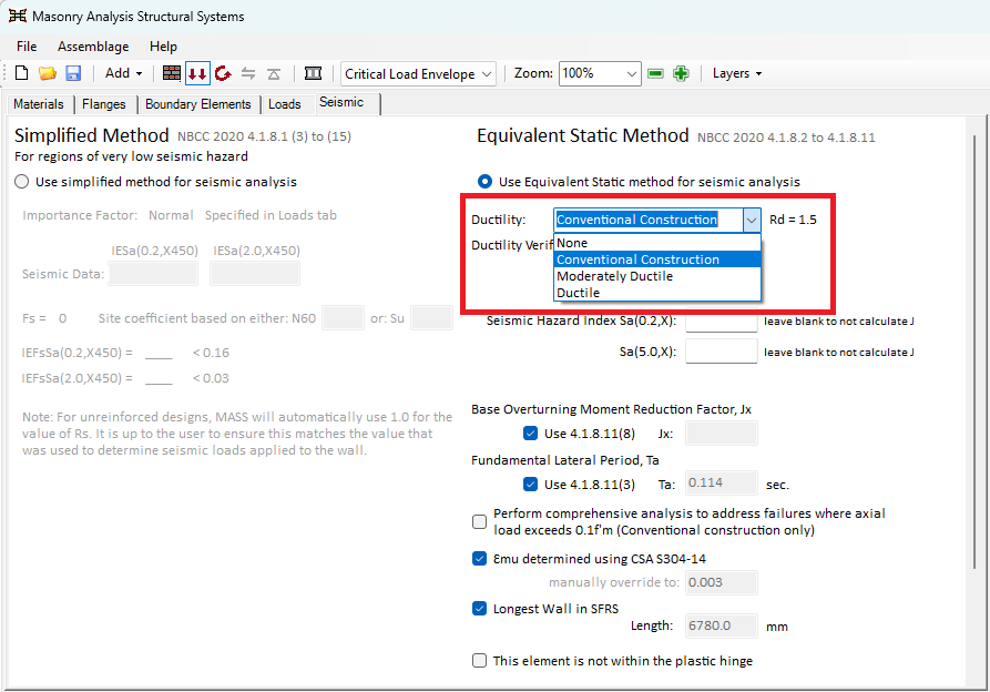 Figure 5‑58: Ductility Selection
After the ductility category has been selected, users must select the seismic category of the wall. This can be determined using NBCC 2020: Table 4.1.8.5-B. Users can select SC1, SC2, SC3, or SC4, as shown in Figure 5-59: Seismic Category Selection.
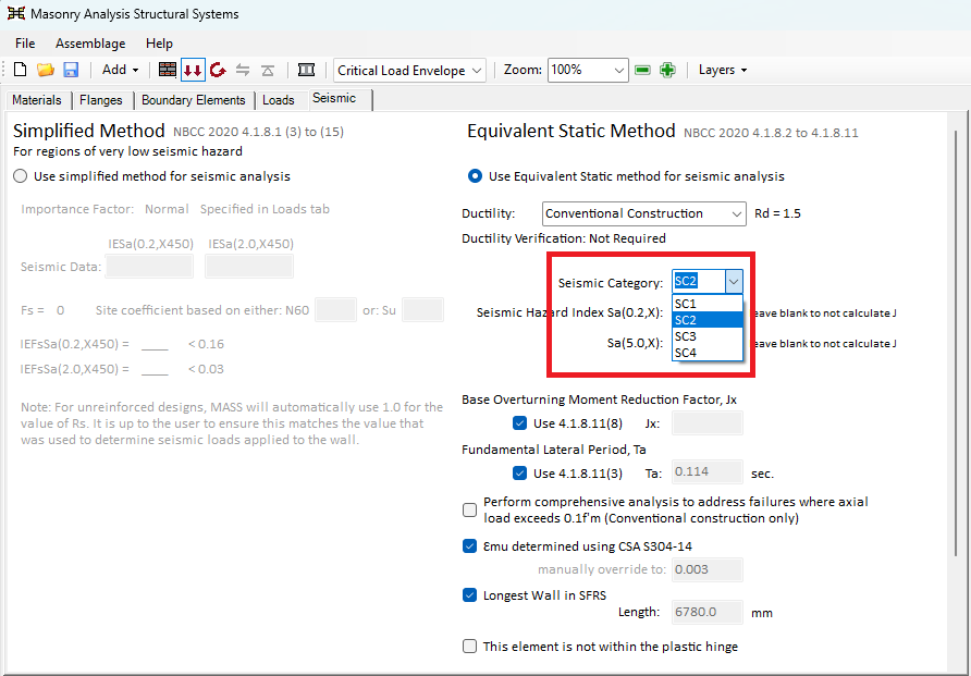 Figure 5‑59: Seismic Category Selection
Once the ductility category and seismic category have been selected, users can enter values for Sa(0.2) and Sa(5.0) if they’d like, which are used by MASS to calculate the base overturning moment reduction factor. If users have already calculated this value, they can de-select the “Use 4.1.8.11(8)” check-box and enter a value for Jx.
Similarly, MASS calculates the fundamental lateral period, εmu, and the longest wall in the SFRS by default. If users prefer to enter these values manually, the corresponding check-boxes can be de-selected and user-defined values can be entered.
For walls designed as Conventional Construction, the axial load on the wall may exceed the limit of 0.1f’m. If this occurs, users can select the “Perform comprehensive analysis to address failures where axial load exceeds 0.1f’m (Conventional construction only)” check-box. This option should generally only be selected if the design is unsuccessful due to the 0.1f’m axial load limit. For more information on this procedure, refer to the following article. MASS documentation notes that the comprehensive analysis option was added to address cases where the axial load exceeds 0.1f’m for Conventional Construction shear walls.
Lastly, users can specify whether the wall is located within the plastic hinge region. For walls located higher in a structure, the wall may be outside of the plastic hinge region. In these cases, users can de-select the plastic hinge region option where appropriate.
Moment Design
Moment design is the third step in developing a shear wall design. In this step the program iterates through the selected parameters and designs a shear wall such that the total moment resistance due to masonry and all steel reinforcement is greater than or equal to the largest moment at the critical section of the shear wall, for any combination of input loads. The moment resistance is calculated for each load combination by setting the factored axial load equal to the axial resistance and solving for the corresponding moment resistance. For shear walls that are not symmetric, and when users have selected to ‘Apply the Load in Both Directions’ (Figure 5‑53: Applying Loads in Both Directions), the program calculates the moment resistance in both directions and compares the smaller of the two to the largest moment at the critical section of the shear wall.
In order run the moment design:
- Click on the Moment Design button
 , as shown in Figure 5‑60: Moment Design Step.
 Figure 5‑60: Moment Design Step
Notice that when performing the moment design step, the Moment Design button is outlined in blue. Notice, also, that prior to running the moment design step, the ‘Minimum Clearances’ box is disabled, and there is no location where users can specify the vertical reinforcement properties. Users are required to run the moment design step before specifying any changes.
Successful Moment Design
Highlighted in green are the masonry unit properties and the steel properties that provide a successful design, as can be seen in Figure 5‑61: Moment Design (Successful). Notice users cannot alter the vertical steel properties (including the minimum clearances) until the moment design step has begun. Notice, also, that the design selections are reflected in the shear wall drawing.
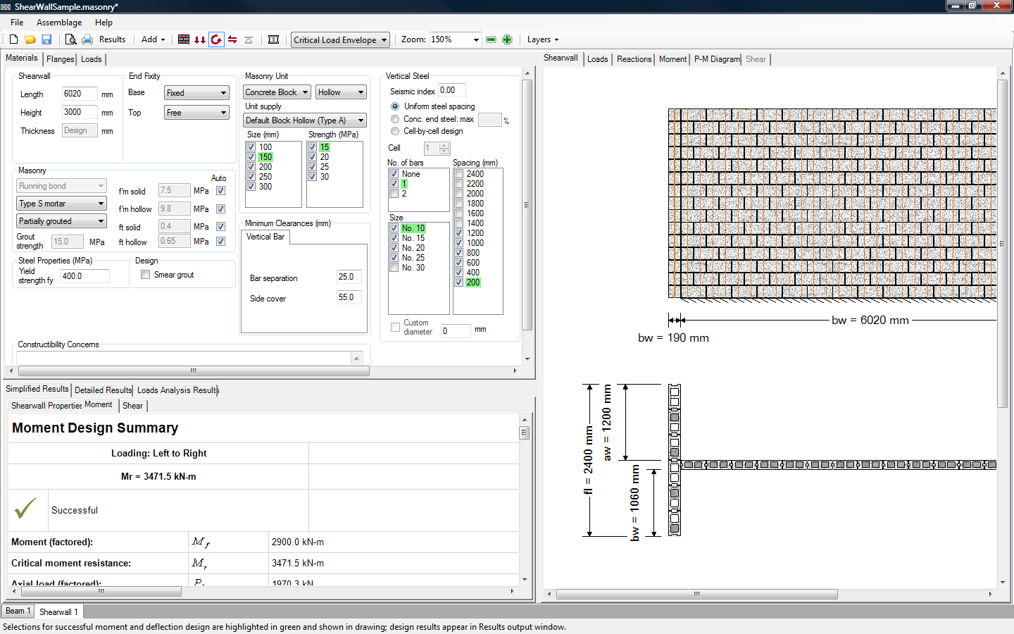 Figure 5‑61: Moment Design (Successful)
![]() Note: The ability to place vertical steel is disabled if the grouting pattern selected is not grouted because grout is required to anchor vertical steel.
Note: The ability to place vertical steel is disabled if the grouting pattern selected is not grouted because grout is required to anchor vertical steel.
Notice that upon moving into the moment design step, the program automatically displays the Simplified Results → Moment tab in the bottom window. The ‘Moment Design Summary’ page as well as the status bar at the bottom of the page informs users whether or not a successful design is found. To achieve
Figure 5‑62: Moment Design Summary (Successful Design)‑, the top margin of the bottom left window was extended up. For more information on adjusting window sizes refer to the Windows and Margins section.
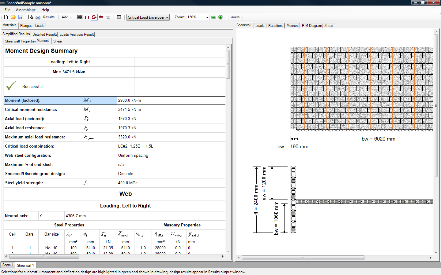 Figure 5‑62: Moment Design Summary (Successful Design)
For a partially grouted or fully grouted wall, by default, the number of bars per cell is none. That is, the program attempts to design an unreinforced shear wall first. If the wall does not provide enough capacity, or does not meet seismic reinforcement requirements, then vertical reinforcement is placed in the web of the shear wall, beginning with the smallest number of bars per cell available, the smallest bar size available, and the largest spacing available. For more information on the design strategy of the program, refer to the Moment Design Strategy section.
![]() Note: Due to the large number of iterations the program performs, it may take up to several minutes to reach a successful design. If the program requires more than several seconds to reach a solution, the smaller weaker blocks, or larger bar spacing and smaller bar sizes do not provide enough capacity. In this case, users can easily de-select some of the early iterations in the midst of the design process. This will significantly speed up the program. Refer to the Moment Design Strategy section for further details.
Note: Due to the large number of iterations the program performs, it may take up to several minutes to reach a successful design. If the program requires more than several seconds to reach a solution, the smaller weaker blocks, or larger bar spacing and smaller bar sizes do not provide enough capacity. In this case, users can easily de-select some of the early iterations in the midst of the design process. This will significantly speed up the program. Refer to the Moment Design Strategy section for further details.
Vertical Steel
Upon the completion of a successful or unsuccessful moment design, users may wish to alter the design provided by the program. Under the Materials tab, users can change any of the material properties previously entered or selected. The program automatically re-triggers the moment design step if any of the check-box material selections are altered. For new values that are entered into a textbox (for instance, the height of the shear wall) press Enter on the keyboard to re-trigger a design.
![]() Note: To add new loads, click on the Loads tab. This returns the program to the loads input design step. It will be necessary to repeat the moment design step.
Note: To add new loads, click on the Loads tab. This returns the program to the loads input design step. It will be necessary to repeat the moment design step.
Uniform Steel Spacing Mode
The ‘Uniform steel spacing’ mode is the default design mode in the shear wall module. The first design performed by the program always uses the ‘Uniform steel spacing’ mode. Using this mode, the program places vertical reinforcement at equal spacing along the length of the web. For example, a wall containing one No. 10 bar per cell, spaced at 200 mm is shown in Figure 5‑63: Uniform Steel Spacing Mode (150 mm unit, 15 MPa, 1 bar/cell, No. 10 bars, 200 mm spacing).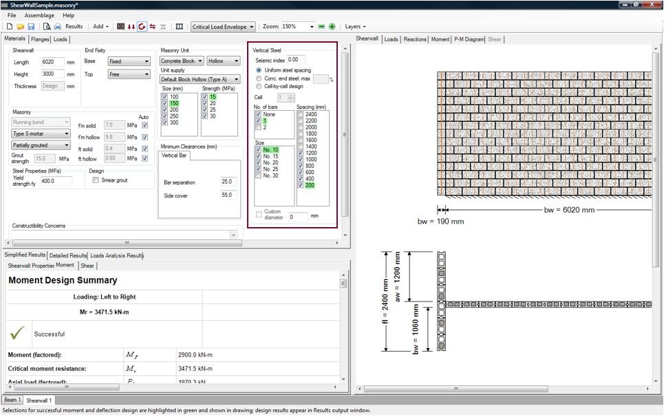
Figure 5‑63: Uniform Steel Spacing Mode (150 mm unit, 15 MPa, 1 bar/cell, No. 10 bars, 200 mm spacing)
One way to change to ensure a fully grouted wall is to select a 200 mm. Even if a partially grouted grouting pattern is selected in the assemblage configuration design step, the 200 mm spacing results in a wall that is fully grouted.
A better way to ensure a fully grouted wall is the change the grouting pattern directly (using the grouting pattern drop-down box indicated in Figure 5‑64: Altering Masonry Properties AFTER the Moment Design Step‑. Altering the grouting pattern may significantly change the design. If grouting pattern of the wall shown in Figure 5‑63: Uniform Steel Spacing Mode (150 mm unit, 15 MPa, 1 bar/cell, No. 10 bars, 200 mm spacing)‑ is changed to fully grouted (Figure 5‑64: Altering Masonry Properties AFTER the Moment Design Step‑), the grout itself provides enough capacity, and steel reinforcement bars are not necessary. Notice that the program now uses ‘None’ for the ‘No. of bars’ in a cell. By default, the two bars per cell is checked-off and needs to be specifically selected by the designer before it is included as a design option.
Notice, the program has selected a smaller masonry unit size (100 mm) with a larger strength (30 MPa).
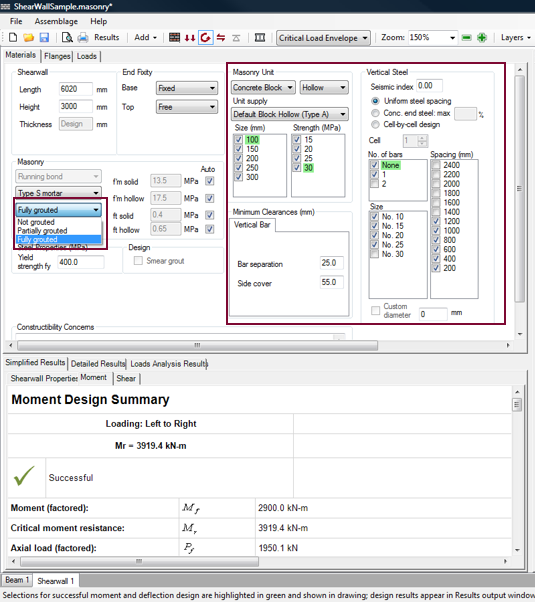 Figure 5‑64: Altering Masonry Properties AFTER the Moment Design Step
The current version of the program only allows for a reinforced web if the flanges are reinforced (and vice versa). Thus, if users remove all reinforcement from the web, the whole shear wall must be designed as unreinforced (i.e. the flanges must be treated as unreinforced as well).
To increase the spacing of the vertical bars shown in Figure 5‑63: Uniform Steel Spacing Mode (150 mm unit, 15 MPa, 1 bar/cell, No. 10 bars, 200 mm spacing)‑ to 400 mm, but keep, for example, the size of the masonry unit (150 mm) and the bar size (No. 10) the same, de-select all masonry unit sizes larger than 150 mm, and all bar sizes larger than No. 10. De-select ‘None’. Then de-select all bar spacing possibilities except for 400 mm, as shown in Figure 5‑65: Steel Spacing Mode (150 mm unit, 20 MPa, 1 bar/cell, No. 10 bars, 400 mm spacing).
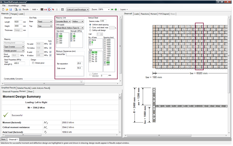 Figure 5‑65: Steel Spacing Mode (150 mm unit, 20 MPa, 1 bar/cell, No. 10 bars, 400 mm spacing)
Notice that at the centre of the wall, the spacing of the two bars is not 400 mm. This is because MASS begins by placing bars at the two ends of the web, and then places consecutive bars at the specified spacing, moving inwards towards the centre of the wall. It is therefore possible for the spacings, when meeting at the centre from either end, to overlap. For a more detailed explanation, refer to the Moment Design Strategy section. The program provides the option of altering the configuration of the wall on a cell-by-cell basis (so this configuration can be readily altered).
Concentrated End Steel Mode
The ‘Concentrated End Steel’ mode is selected by clicking on the corresponding radio button shown in Figure 5‑66: Concentrated End Steel Mode‑.
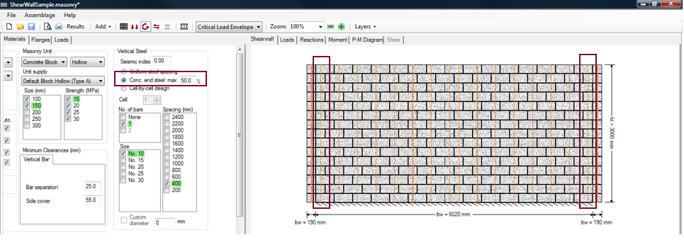 Figure 5‑66: Concentrated End Steel Mode
Using the ‘Concentrated end steel’ mode, the program places vertical reinforcement at equal spacing along the length of the web. In addition, the program places additional steel at each end of the web which can provide more moment capacity. Notice, however, that MASS places a limit on the amount of steel that is placed at the ends. It is advisable to limit the amount of steel placed at the ends, in order limit the size of the cracks and improve the overall performance of reinforced masonry shear walls. In the program, limiting the amount of additional end steel typically increases the amount of uniformly distributed steel along the web, especially for longer shear walls.
The maximum amount of steel (by area) permitted at the ends is specified by users as a percentage of the total steel in the web. This maximum amount is applied only when adding steel to the ends. The default percentage is 50% (or 25 % per end), as shown in Figure 5‑66: Concentrated End Steel Mode. To enter a new maximum steel percentage, type in the amount in the textbox to the right of the ‘Concentrated end steel’ radio button. Press Enter on the keyboard. In general, users are advised against using a total maximum percentage larger than 60% (or 30% per end).
![]() Note: Additional end zone steel will not be placed if a successful design is found without applying end zone steel. MASS™ always checks designs without using end zone steel before adding end zone steel in an effort to minimize reinforcement used for a successful design.
Note: Additional end zone steel will not be placed if a successful design is found without applying end zone steel. MASS™ always checks designs without using end zone steel before adding end zone steel in an effort to minimize reinforcement used for a successful design.
Cell-by-Cell Design Mode
The ‘Cell-by-cell design’ mode is selected by clicking on the corresponding radio button shown in Figure 5‑607: Cell-by-Cell Design Mode‑.
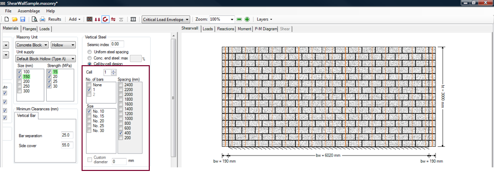
Figure 5‑67: Cell-by-Cell Design Mode
The program must first perform a design using the ‘Uniform steel spacing’ mode. The starting point for a design using the ‘Cell-by-cell design’ mode is the resulting configuration from the previous steel placement mode (whether it is the uniform steel spacing mode or the concentrated end steel mode). Using this mode, users can alter the previous configuration, or specify an entirely new configuration by changing the vertical steel properties in each cell.
![]() Note: When returning to the ‘Concentrated end steel’ mode or the ‘Uniform steel spacing’ mode, the vertical steel configuration specified in the ‘Cell-by-cell design’ mode will be lost.
Note: When returning to the ‘Concentrated end steel’ mode or the ‘Uniform steel spacing’ mode, the vertical steel configuration specified in the ‘Cell-by-cell design’ mode will be lost.
The vertical reinforcement in a web for the ‘Cell-by-cell design’ mode is specified in a similar manner as vertical reinforcement is specified in the flanges. The only important difference is that vertical reinforcement changes cannot be made to a whole range of cells. This is why the ‘Spacing’ check-boxes are shaded in grey, and therefore disabled (Figure 5‑67: Cell-by-Cell Design Mode‑). Instead, each cell is specified individually.
![]() Note: All properties selected outside of the ‘Vertical steel’ box cannot be specified on a cell-by cell basis. These properties apply to the entire length of the web.
Note: All properties selected outside of the ‘Vertical steel’ box cannot be specified on a cell-by cell basis. These properties apply to the entire length of the web.
To alter the vertical reinforcement in a cell:
- Choose the cell number
- Select the number of bars per cell
- Select the bar size
MASS numbers the cells in a web from left to right. A sample shear wall cross-section with six cells is shown in Figure 5‑68: Flange Cell Count. Vertical reinforcement cannot be placed into a partial cell, so a partial cell (if applicable) is not included in the cell count.
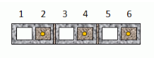 Figure 5‑68: Flange Cell Count
The default cell number is 1. To change the cell number, use the up or down arrows, or type the cell number into the textbox. This is shown in Figure 5‑69: Cell Number in Web.
 Figure 5‑69: Cell Number in Web
To alter cell number 11, for example, type in 11 into the cell number textbox (Figure 5‑70: Altering the Vertical Steel Properties of Cell Number 11‑), as press Enter on the keyboard.
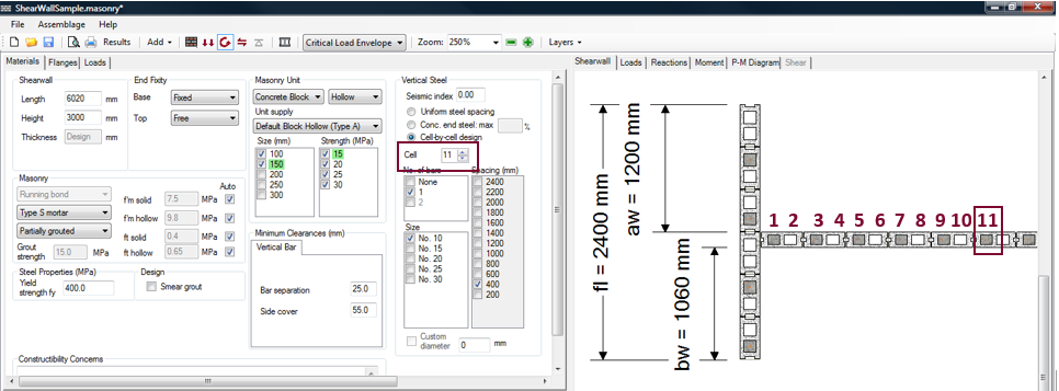 Figure 5‑70: Altering the Vertical Steel Properties of Cell Number 11
Notice that because this cell is originally ungrouted, and ‘None’ is selected in the ‘No. of bars’ check-box, the ‘Size’ check-boxes and the ‘Spacing’ check-boxes in this case are grey to indicate they are disabled. To activate the size or strength check-boxes for a particular cell number chosen users must select either ‘1’ or ‘2’ ‘No. of bars’, rather than ‘None’.
![]() Note: If there are two bars placed in one cell, MASS requires that the bars be of the same size. It is not possible for users to select the specific size of the two bars independently.
Note: If there are two bars placed in one cell, MASS requires that the bars be of the same size. It is not possible for users to select the specific size of the two bars independently.
To select the bar size desired for the particular cell number chosen, check-on the desired bar size check-box. Notice that only one of each can be selected for a single cell. The program does not iterate through the number of bars in a cell, or the bar size when in the ‘Cell-by-cell design’ mode.
For a bar size not specified in the check-box list, enter the bar diameter into the ‘Custom diameter’ textbox, and press Enter. The ‘Custom diameter’ check-box is automatically checked-on. A custom diameter of 22.225 mm is specified in cell number 10, as exemplified Figure 5‑71: Entering a Custom Bar Diameter‑. This diameter specified as 22.225 in millimetres is equivalent to 0.876=7/8 inches. Following the American reinforcement bar sizes, this is the diameter of a No. 7 bar.
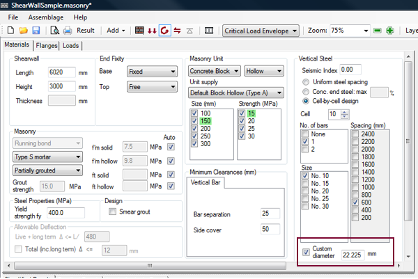 Figure 5‑71: Entering a Custom Bar Diameter
![]() Note: Imperial bar sizes must be entered in metric units in the custom diameter textbox.
Note: Imperial bar sizes must be entered in metric units in the custom diameter textbox.
The custom diameter size is limited to a 30 mm diameter bar. This feature was introduced to allow for imperial reinforcement bar sizes, which are used in some locations in Canada, particularly those in close proximity with the United States border.
![]() Note: MASS provides a lot of versatility and allows for users to change the vertical steel configuration for each cell. Because of this, it is possible for users to specify some rather exotic or difficult to construct shear walls. For instance, a designer could specify a web with varying bar sizes. The use of different bar sizes inside the same cell is not practical and can lead to confusion during installation. In most cases, webs with uniformly distributed vertical steel tend to perform better, are easier to construct and design, and are thus recommended.
Note: MASS provides a lot of versatility and allows for users to change the vertical steel configuration for each cell. Because of this, it is possible for users to specify some rather exotic or difficult to construct shear walls. For instance, a designer could specify a web with varying bar sizes. The use of different bar sizes inside the same cell is not practical and can lead to confusion during installation. In most cases, webs with uniformly distributed vertical steel tend to perform better, are easier to construct and design, and are thus recommended.
In all reinforced walls there must be at least two bars in the web in order to compare their spacing to the minimum spacing requirements. If a user manually alters the design such there is only one bar in the web, the minimum spacing requirements are not met and thus the design fails. In the case of multiple spacings, the minimum spacing requirements are compared to the largest spacing found in the web. For more information on spacing requirements refer to CSA S304-14: 10.15.1.2 and 16.4.5.3.
Minimum Clearances
MASS places limitations on the possible vertical steel configurations. These possible configurations are based on the current block size as well as the bar separation and side cover. The bar separation and side cover can be manipulated using the ‘Minimum Clearances’ box shown in Figure 5‑72: Entering Minimum Clearances‑. The bar separation is a user input, with a default value of 25 mm. The side cover is also a user input with a default value of 55 mm.
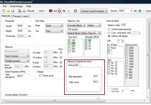 Figure 5‑72: Entering Minimum Clearances
The bar separation entered in Figure 5‑72: Entering Minimum Clearances‑, refers to the separation between the outer surfaces of any two steel bars within a cell. The side cover, refers to the minimum separation between the outer surfaces of the face of the block to the outer surfaces of the nearest reinforcing bar.
The bar separation and side cover are used to determine the location in the cell where the vertical reinforcement steel can be placed, and should meet the requirements for coarse grout. Refer to CSA A371: 8.2.5.7.1 and CSA A165.1-14: 6.2 and 6.3.
For the shear wall module, the vertical steel bars are centred within the width of the block, and placed at the specified bar separation. The side cover does not play a direct role in the placement of the vertical steel. It merely provides a minimum distance between the outer surfaces of the face of the block to the outer surfaces of the nearest reinforcing bar.
For example, a 20 cm unit, with two bars per cell (size No. 10), with a default minimum bar separation of 25 mm, and a minimum side cover (the value entered into the textboxes) is 55 mm as is shown in Figure 5‑73: Minimum Clearance.
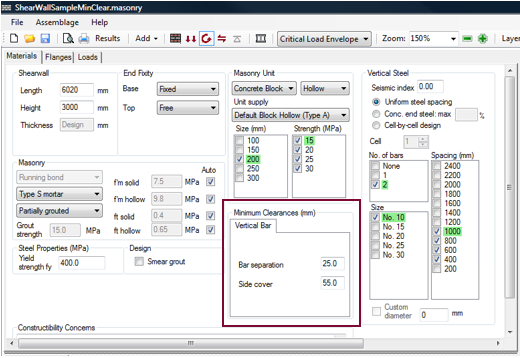 Figure 5‑73: Minimum Clearance
Observe, however, that the minimum side cover is not the same as the actual side cover, as shown in Figure 5‑74: Actual Side Cover.
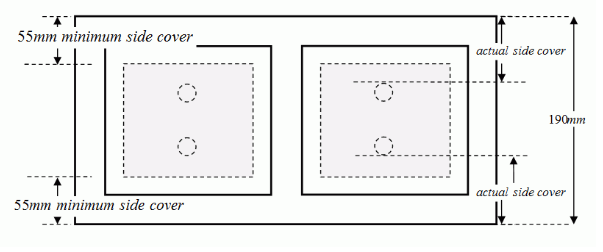 Figure 5‑67: Actual Side Cover
The actual side cover is determined using the bar separation as follows:
 Internally, the program checks to ensure that the actual side cover is larger than the minimum side cover entered by the user.
The user is not permitted to enter a side cover smaller than the minimum. The minimum side cover must be at least the face shell thickness plus an additional distance of 13 mm to any surface of masonry (spacing required for coarse grout from CSA A371: 8.2.5.7.1).
![]() Note: Minimum clearances cannot be specified for each cell. The bar separation, and side cover specified applies to all reinforced cells along the length of the web.
Note: Minimum clearances cannot be specified for each cell. The bar separation, and side cover specified applies to all reinforced cells along the length of the web.
Unsuccessful Moment Design
Figure 5‑68: Moment Design (Unsuccessful)‑ provides an example of an unsuccessful moment design.
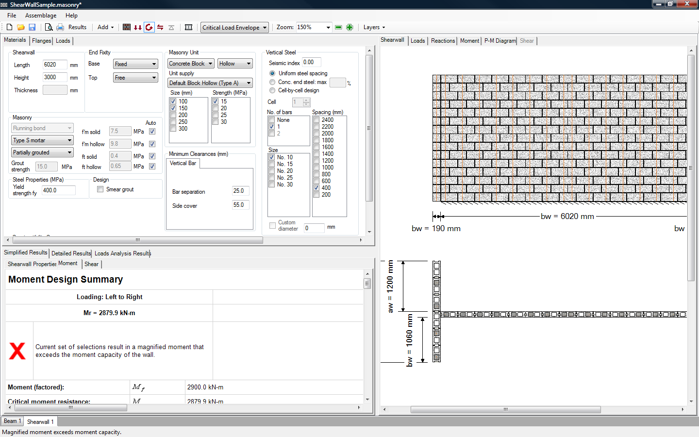 Figure 5‑75: Moment Design (Unsuccessful)
Notice that many parameters that were checked-on in Figure 5‑61: Moment Design (Successful) have been de-selected (by the user), meaning these properties are not to be included as possible parameters for the design. The selected properties did not result in a wall that could resist the applied loads (Figure 5‑75: Moment Design (Unsuccessful)).
 Figure 5‑76: Moment Design Summary (Unsuccessful Design)
The ‘Moment Design Summary’ page as well as the status bar at the bottom of the page informs users whether or not a successful design is found. Notice in the status bar, that the moment design has been performed, notice also, that there are no masonry unit or vertical steel selections that are highlighted in green (Figure 5‑75: Moment Design (Unsuccessful)‑).
In general, an unsuccessful design is altered in the same manner as a successful design. For example, check-on the No. 10 bar size, and allow for a smaller bar spacing by checking-on the ‘400’ mm spacing check-box.
The program now provides a successful design, as shown in Figure 5‑77: Compression-Controlled Shear Wall.
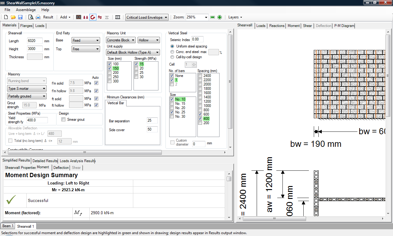 Figure 5‑77: Compression-Controlled Shear Wall
It may come as a surprise that the parameters selected in Figure 5‑77: Compression-Controlled Shear Wall‑ provide a successful design, since the No. 25 bars spaced at 600 mm (Figure 5‑76: Moment Design Summary (Unsuccessful Design)‑) provide more area of steel along the length of the web then No. 10 bars at 400 mm. However, observe that the reduction in steel spacing has resulted in the addition of more grout. That is, it is not the steel that has altered the capacity shear wall. Rather, it is the added grout that has increased the capacity of the shear wall. For the compression-controlled shear walls (where the axial load is typically large), it may be beneficial for the designer to consider fully grouting the flanges and the web, and removing the reinforcement. Always re-trigger the moment design to ensure that the fully grouted unreinforced shear wall can resist the applied loads and moments.
![]() Note: If the program produces a successful design using a No. 10 bar it is likely that the shear wall is compression-controlled (thus, requiring more grout). This is typically a consequence of the design strategy employed by the program. For more information on the design strategy, refer to Shear Wall Design Strategy.
Note: If the program produces a successful design using a No. 10 bar it is likely that the shear wall is compression-controlled (thus, requiring more grout). This is typically a consequence of the design strategy employed by the program. For more information on the design strategy, refer to Shear Wall Design Strategy.
The unsuccessful design exemplified in Figure 5‑75: Moment Design (Unsuccessful)‑ is a common problem that designers face when using MASS. This failure occurs not because an acceptable solution does not exist, but because users limited the parameter options the program has. To ensure that there are no possible solutions with any of the parameters available to the program, users are encouraged to allow the program to provide a design with all check-boxes selected (that is, checked-on). It is easier to begin eliminating the masonry units or steel configurations after a completed successful design than it is to select additional properties the program can use after a failed design. Furthermore, if the program does not find a successful design with all masonry and steel properties checked-on, the designer can be sure the program has attempted to design a shear wall using all possible parameters and their combinations, and that with the loads applied, no solution is possible. In this case, the displayed design uses the largest block size available, the largest bar size available, at the smallest spacing available. This is because of the way the program iterates through the possible solutions. For more information on the design strategy the program applies, refer to Shear Wall Design Strategy.
Moment Design Results
Upon the carrying out a successful or unsuccessful moment design, the shear wall drawing is available (displaying the masonry and vertical steel properties used in the design). The simplified and detailed results for the moment design are also available. The moment design step is not fully completed until the shear design step is completed. This is because the shear design step may warrant use of additional vertical steel. Additional steel will impact the existing moment calculations. Refer to A Complete Shear Wall Design for a complete discussion on the moment design results.
Shear Design
Shear design is the forth step in developing a shear wall design. In order run the shear design:
- Click on the Shear Design button
 , as shown in Figure 5‑78: Shear Design Step. The program does not allow users to perform the shear design step until the moment design step is complete.
 Figure 5‑78: Shear Design Step
Notice that when performing the shear design step, the shear design button is outlined in blue.
Using the shear wall configuration from the moment design step, the program calculates the in-plane shear resistance and the in-plane sliding shear resistance of the wall. It then compares the shear resistance and the sliding shear resistance to the factored shear at the critical section (where the factored shear value is the largest along the height of the shear wall).
Unsuccessful Shear Design
The design provided in Figure 5‑61: Moment Design (Successful)‑ fails in shear, as can be seen in Figure 5‑79: Moment Design (Unsuccessful).
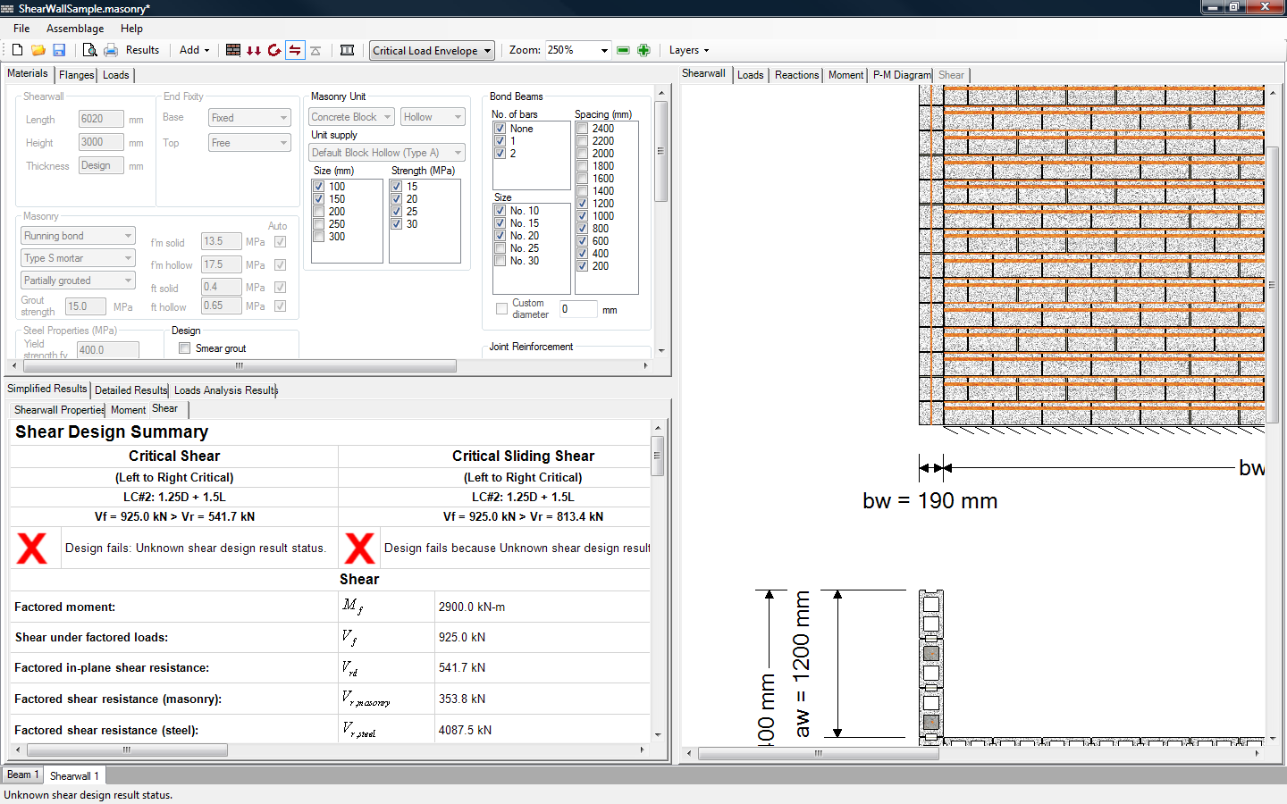 Figure 5‑79: Moment Design (Unsuccessful)
Using the shear wall configuration from the moment design step, the program calculates the in-plane shear resistance and the in-plane sliding shear resistance of the wall. If the factored shear at the critical section (where the shear value is the largest along the height of the wall) is larger than the shear resistance (Vf > Vrd) the current shear design iteration fails. Refer to CSA S304-14: 7.10.2.1 and 10.10.2.1 for additional information on calculating in-plane shear.
If the factored shear at any course height is larger than the sliding shear resistance at any course height (Vf,i > Vr,sliding), the current shear design fails. Refer to CSA S304-14: 7.10.2.1 and 10.10.5.1 for additional information on calculating in-plane sliding shear.
If all the possible horizontal steel iterations are exhausted, the program increments the block size/strength and redesigns for the moment and then the shear. For more information on the design strategy used in the shear wall module, refer to the Shear Design Strategy section.
Since the program begins with the parameters that resulted in a successful moment design, it does not change the shear wall design unless the original design did not provide enough shear capacity.
The program automatically re-triggers the moment design step if any of the check-box material selections are altered. For new values that are entered into a textbox (for instance, the height of a shear wall) press Enter on the keyboard to re-trigger the moment design.
If the program does not highlight in green any of the masonry properties, the shear design failed. The selected properties did not result in a wall that could resist the applied loads. The status bar at the bottom of the page informs users of a failed design, and the Simplified Results → Shear tab shows a red ‘X’. An unsuccessful design can be altered by checking-on more masonry properties (if they are available).
Successful Shear Design
The masonry unit properties and the vertical and horizontal steel properties that provide a successful design, are typically highlighted in green. A sample shear wall that successful passes in shear is shown in Figure 5‑80: Shear Design (Successful).
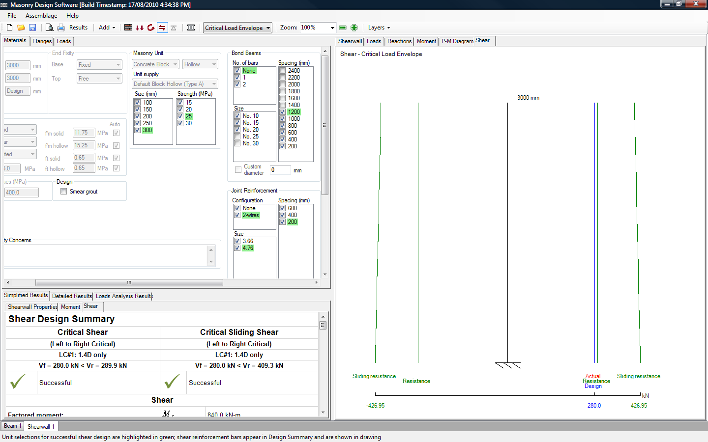 Figure 5‑80: Shear Design (Successful)
Upon moving into the shear design step, the program automatically displays the Simplified Results → Shear tab in the bottom window. Upon the carrying out a successful shear design, the shear wall drawing is available, displaying the masonry, the vertical steel, and the horizontal steel properties used in the design. Also, a successful design status is shown in the ‘Shear Design Summary’, as well as, in the status bar. The horizontal steel properties used in the shear wall assemblage are not highlighted in green because the properties may change along the length of the assemblage. The horizontal steel used is however displayed in the shear wall drawing.
Notice, users cannot alter the horizontal steel properties until the shear design step has begun.
Horizontal Steel
Upon the completion of a successful or unsuccessful shear design, users may wish to alter the design provided by the program. Under the Materials tab, users can change any of the masonry properties previously entered or selected. The program automatically re-triggers the moment design step and the shear design step if any of the check-box material selections are altered.
Users can now also change the horizontal steel properties used in the design. Horizontal reinforcement is used to resist diagonal shear stresses. CSA S304-14 permits the use of horizontal reinforcing bars (bond beams) and joint reinforcement (wire installed in the mortar joint), individually or in combination with each other.
Bond Beams
Bond beams are one course high beams with reinforcing bars placed along the length of the wall, as shown in Figure 5‑81: Horizontal Reinforcement (Bond Beams).
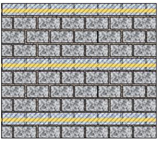 Figure 5‑81: Horizontal Reinforcement (Bond Beams)
To alter the bond beam reinforcement along the height of the shear wall:
- Select the bond beam configuration (0, 1 or 2 bars per bond beam)
- Select the bar size (No. 10, 15, 20, and 25)
- Select the bond beam spacing (from 200 mm to 2400 mm, at 200 mm intervals)
There are restrictions placed on the maximum bond beam spacing. For bond beams alone, the maximum non-seismic reinforcement spacing permitted is 2400 mm (CSA S304-14: 10.15.1.3), and the maximum seismic reinforcement spacing permitted is 1200 mm (CSA S304-14: 16.4.5.4). For a shear wall with bond beams and joint reinforcement, the maximum spacing permitted by CSA S304-14: 10.15.1.3 and CSA S304-14: 16.4.5.4 is 2400 mm for the bond beams and 400 mm for the joint reinforcement
The program allows a maximum of two bars in a bond beam. The horizontal bars are placed at a knockout depth of 100 mm (from the top on the bond beam). The bar sizes are limited by the unit size (space in a cell). To simplify the bar size limitation, the program assumes that the same bars that fit in the vertical direction fit in the horizontal direction.
![]() Note: If a user selects ‘not grouted’, the walls must be unreinforced in both the vertical direction and the horizontal selection. Vertically unreinforced walls are permitted to have bond beams or joint reinforcement, so long as the ‘partially grouted’ or ‘fully grouted’ condition was selected by users. Adding bond beams in a partially grouted wall may increase its self-weight, since bond beams are fully grouted courses of masonry.
Note: If a user selects ‘not grouted’, the walls must be unreinforced in both the vertical direction and the horizontal selection. Vertically unreinforced walls are permitted to have bond beams or joint reinforcement, so long as the ‘partially grouted’ or ‘fully grouted’ condition was selected by users. Adding bond beams in a partially grouted wall may increase its self-weight, since bond beams are fully grouted courses of masonry.
Joint Reinforcement
Joint reinforcement consists of thin wires placed within the horizontal (bed) joint of the masonry wall, as shown in Figure 5‑82: Horizontal Reinforcement (Joint Reinforcement)‑.
![]() Figure 5‑82: Horizontal Reinforcement (Joint Reinforcement)
Figure 5‑82: Horizontal Reinforcement (Joint Reinforcement)
In practice, there are two main types of joint reinforcement; ladder (Figure 5‑83: a) and truss (Figure 5‑83: b). MASS designs for shear using ladder type joint reinforcement only.
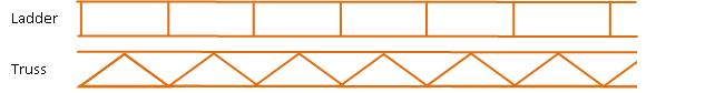 Figure 5‑83: Joint Reinforcement: a) Ladder and b) Truss)
To alter the joint reinforcement along the height of the shear wall:
- Select the joint reinforcement size 3.66mm (standard, side wire or cross wire), 4.76 mm (heavy duty, side wire), and 3.66 (heavy duty, cross wire)
- Select the joint reinforcement spacing (from 200 mm to 600 mm, at 200 mm intervals)
There are restrictions placed on the maximum joint reinforcement spacing. For joint reinforcement alone, the maximum non-seismic reinforcement spacing permitted is 600 mm for 50% running bond and 400 mm for other patterns (CSA S304-14: 10.15.1.3). For shear walls, only running bond is allow in MASS. The maximum seismic reinforcement spacing permitted is 400 mm (CSA S304-14: 16.4.5.4). For a shear wall with bond beams and joint reinforcement, the maximum spacing permitted by CSA S304-14: 10.15.1.3 and CSA S304-14 16.4.5.4 is 2400 mm for the bond beams and 400 mm for the joint reinforcement.
The program does not show bends or hooks at the end of the reinforcing bars. For this version, the program assumption is that the bar configuration input extends for the entire height of the wall.
Shear Design Results
Upon the carrying out a successful or unsuccessful shear design, the shear wall drawing is available (displaying the masonry and vertical steel properties used in the design). The simplified and detailed results for the shear design are also available. Refer to A Complete Shear Wall Design for a complete discussion on the shear design results.
Upon the completion of the shear design step, the shear wall design is complete.
 Warning: Detailing work is left up to the designer. MASS does not account for splice lengths, development length, epoxy coating, etc.
Continue Reading: A Complete Shear Wall Design
Was this post helpful?