

Shearline Design Steps
Shearline Design Steps
This section provides in-depth detail on the steps necessary to complete a shearline design using MASS™.
Assemblage Configuration
The initial steps of creating a shearline are the same as a regular shear wall. The Assemblage Configuration button is highlighted automatically in blue, as seen in Figure 1. This stage is where the material properties as well as the geometry of the shearline can be specified. These are the only options available in the Materials tab until more information has been specified.
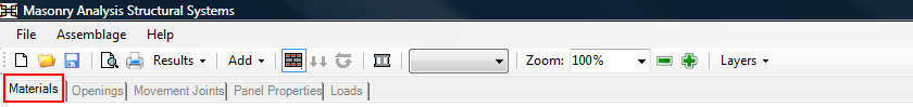 Figure 1: Materials tab located above the input window
Materials Tab
Contents
Within the Materials tab, users can specify the reinforcement and masonry properties used in the shearline design. To specify these properties, follow the same steps and procedures used in shear wall module:
- Enter the dimensions (length, height in mm)
- Select the type of masonry unit (hollow, semi-solid or solid concrete)
- Choose the unit size and strength options
- Provide the masonry properties
- Provide the steel properties
- Choose to smear the grout (optional)
For additional information on the steps listed above, click here to view the shear wall instructions.
One notable difference between the Materials tab seen in a shear wall module and that of a shearline module is that the End Fixity input area is replaced by the Group Properties, shown below in Figure 2 : Shear wall fixity controls replaced by Group Properties in the Materials tab.
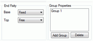 Figure 2 : Shear wall fixity controls replaced by Group Properties in the Materials tab
In all MASS™ shearlines, the base fixity will be set to Fixed while the top will be set to Free. The new addition of the Group Properties controller allows the user to design with multiple unit sizes and strengths within a single shearline.
Groups can be created using the Add Group button and they can also be removed by clicking Delete. Each group stores its own masonry unit properties that can be used in design. These properties are listed below and shown in Figure 3.
- Type of masonry unit (hollow, semi-solid or solid)
- Unit supply (Default Type A, Type C or user created unit)
- Unit size selections (mm)
- Unit strength selections (MPa)
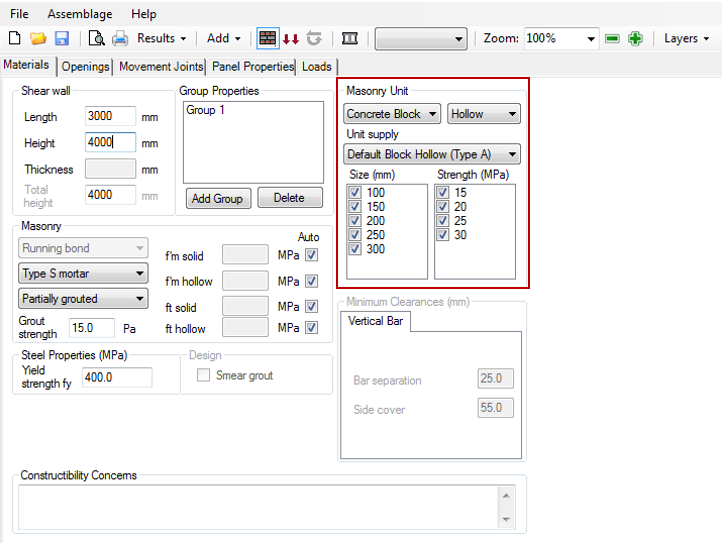 Figure 3: Masonry Unit Properties
By default, there will be only 1 group for the entire shearline. If additional groups are not created, the final design will use a masonry unit with uniform size and strength.
To use more than one masonry unit in a shearline, users can create multiple groups and assign them to individual wall panels as outlined ahead. Different group properties can be selected under the Materials tab and modified for later use in design. The property selections for each group are used in pier design.
Openings Tab
Once users have specified their masonry properties within the materials tab, they can proceed to the Openings tab which will be made available once valid shearline dimensions have been entered, as shown below in Figure 4.
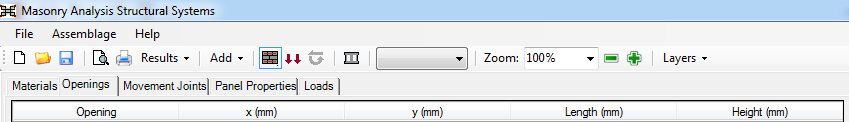 Figure 4: Opening Tab located above the input window
When the Openings tab is selected, users have 2 options in how they can create their openings:
- Using the mouse within the drawing window
- Using the input window to enter in position and dimension values
Drawing Window Interface
The quickest way to create and modify openings is by using the drawing window. The drawing window responds to user input as long as the Openings tab is selected. The drawing window interface snaps the opening locations and dimensions to the nearest modular corner of a masonry unit. For the default metric units, this acts as a grid of 200mm by 200mm squares where all opening edges will align.
Creating a New Opening
To create a new opening using the drawing window, perform the following steps which can be seen below in :
- Left click and hold on the shearline at the location of one of the desired corners of the opening.
- Drag the mouse to the opposite corner of the desired opening location.
- Release the left mouse button to complete the creation of the new opening.
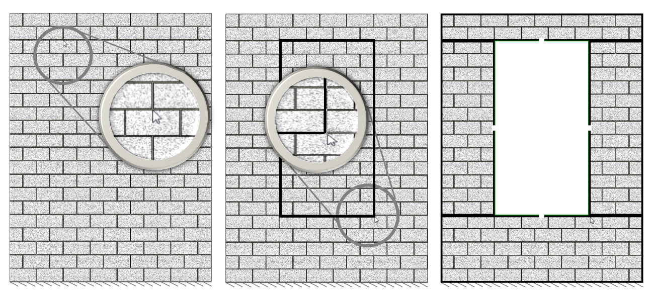 a) Click and hold on one corner b) Drag to opposite corner c) Release left mouse button to complete opening
Figure 5: Creating New Openings using the Drawing Window
As soon as a valid opening is created, the shearline will automatically be divided into piers, as seen as the black outlines above on the shearline to the right in . For more information on pier generation, click here.
Modifying an Existing Opening
To modify an existing opening, there are multiple actions that can be performed on a selected opening. Openings can be selected by clicking on them. An opening must be selected before it can be modified in the drawing window.
Dimensions can be changed by clicking and dragging on the white spaces seen within the green boundaries of a selected opening. Any of the 4 outside edges can be moved as long as it results in a valid configuration. These edges can be moved when the mouse cursor changes to ![]() or
or ![]() .
.
 Figure 6: Modifying an opening within the drawing window
Openings can be moved by clicking and dragging within the white space of the selected opening. An opening can be moved when the mouse cursor changes to ![]() .
.
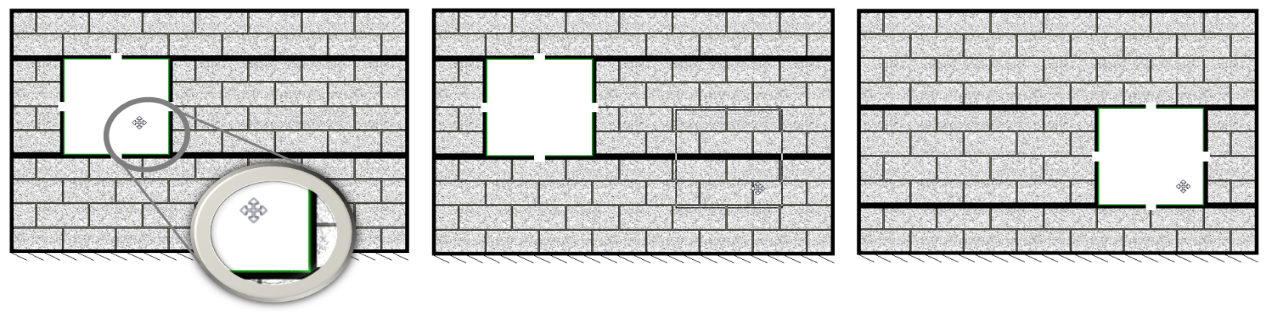 Figure 7: Moving an opening using the drawing window
Deleting an Opening
Openings cannot be deleted in the drawing window. To delete a selected opening, press the Delete Opening button which can be found in the input window. Refer to Figure 12: Delete an Opening to locate the Delete Opening button.
Input Window Interface
Using the input window allows openings to be created and modified based on exact dimensions, rather than snapping everything to the nearest modular corner of a masonry unit.
Creating a New Opening
To create a new opening using the input window, start by clicking the Add Opening button (Figure 8). Once the button is pressed, a new row will appear in the input window with 5 columns (Figure 9). The Opening column shows the number designated to each opening. As more openings are created, their number incrementally increases. The x (mm) and y (mm) columns represent the position of the bottom, left corner of the opening. Users can specify the dimensions of an opening by using the Length (mm) and Height (mm) columns (Figure 10). Once an opening has a length and a height, it is created and displayed in the drawing window (Figure 11).
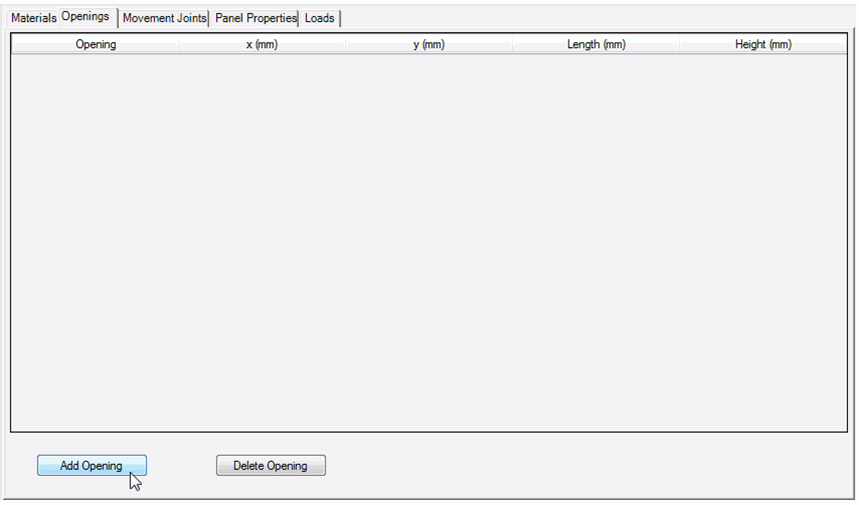 Figure 8: Click “Add Opening” to create an opening using the input window
 Figure 9: Opening is created with position and dimension values initially set to 0mm
 Figure 10: Once all values are entered, the opening is created
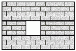 Figure 11: Corresponding change appears in the input window
Modifying an Existing Opening
To change the position or dimensions of an opening, users can simply edit the fields they wish to change in the input window, as long as it does not interfere with movement joints or other openings.
Deleting an Opening
To delete a selected opening, press the Delete opening button which can be found in the input window.
Opening Restrictions
There are some shearline configurations that are not handled by the load distribution process. The shearline user interface prevents invalid shearline configurations from being created and designed. These restrictions are described below.
Interference with Other Openings
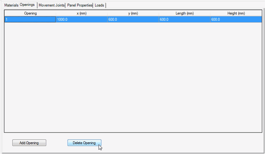
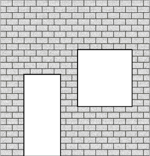
All openings created within a MASS™ shearline must not overlap or be within a unit height or half unit length of one another. Each opening has a zone around it that cannot be contain another opening, as shown below in Figure 14: Warning message when an opening is changed to interfere with another opening.
 Figure 13: Shearline areas shaded in red cannot contain part of another opening within a wall panel. The shaded red zone is for illustrative purposes only and does not appear within the actual software.
When creating openings in the drawing window, the user interface will automatically prevent openings from being dragged next to one another. Making changes to an opening using the input window will result in the error message shown in Figure 14: Warning message when an opening is changed to interfere with another opening. After clicking OK, the most recently changed variable will automatically be reverted back to its previous value.
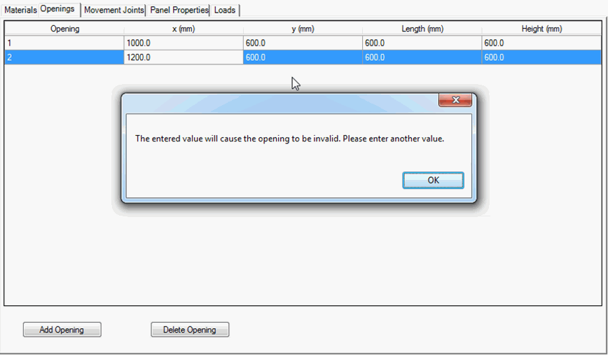 Figure 14: Warning message when an opening is changed to interfere with another opening
Partial Height Overlap
MASS™ breaks up a shearline by creating horizontal strips that match the height of each opening that is created, as seen in Figure 15: Shearline broken into horizontal strips that match the height of each opening. The black horizontal lines show where these strips are drawn along the top and bottom edges of each opening.
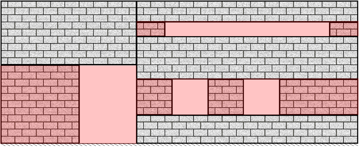 Figure 15: Shearline broken into horizontal strips that match the height of each opening
These strips cannot partially overlap where only part of one strip is contained within another. They are allowed to be completely encompassed (Figure 16: Allowable opening arrangements a) or completely separate but there cannot be a partial overlap. There can also be multiple openings within one strip as seen in Figure 16: Allowable opening arrangements b. Any combination of openings can be used as long as there is not a partial overlap of the strips that these openings would create (Figure 16: Allowable opening arrangements). All of the shearlines shown in Figure 16: Allowable opening arrangements are examples of acceptable shearlines.
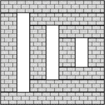 a) Strips encompassing other strips
 b) Strips encompassing multiple openings
 c) Combination of multiple piers within a strip and a strip encompassing another strip
Figure 16: Allowable opening arrangements
The shearline in Figure 17a cannot be designed in MASS™ because the openings are partially overlapping while the shearline in Figure 17b can be because they are separated by a movement joint. For more information on how piers are generated and identified, click here.

a) Invalid shearline configuration b) Valid shearline configuration
Figure 17: Movement Joints used to separate conflicting openings
Movement Joints Tab
The Movement Joints tab (Figure 18: Movement Joints tab located above the input window) is made available once the shearline dimensions have been entered.
 Figure 18: Movement Joints tab located above the input window
When the Movement Joints tab is selected, users have 2 options in how they can create their movement joints:
- Using the mouse within the drawing window
- Using the input window to enter in position, dimension and segment offset values
Drawing Window Interface
Creating a New Movement Joint
To create a new movement joint, click anywhere on the wall to place a movement joint. Movement joints can be placed anywhere as long as they do not intersect any openings or other movement joint offsets.
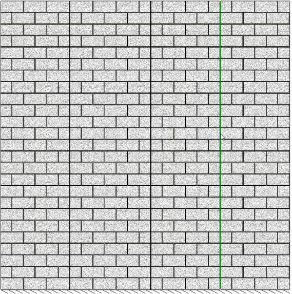 Figure 19: Adding movement joints by clicking on the shearline within the drawing window
As soon as a movement joint is created, the shearline will automatically be divided into wall panels.
Creating a Movement Joint Offset
It can sometimes be useful to create a movement joint that has a horizontal offset along the top of an opening. A movement joint offset can be created through the following steps:
- Click on the point of the movement joint where the offset is to occur. .
- Hold the SHIFT key while hovering over one of the segments.
- When the mouse cursor changes to
 , click and drag the segment to its new location.
 - Release the left mouse button to place the segment at its new location.
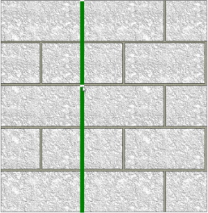

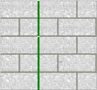

Figure 20: Creating a movement joint offset
This can be done any number of times along a single movement joint. Offsets can also be placed on both sides of an opening as seen in Figure 21: Movement joint with offset placed on both sides of an opening.
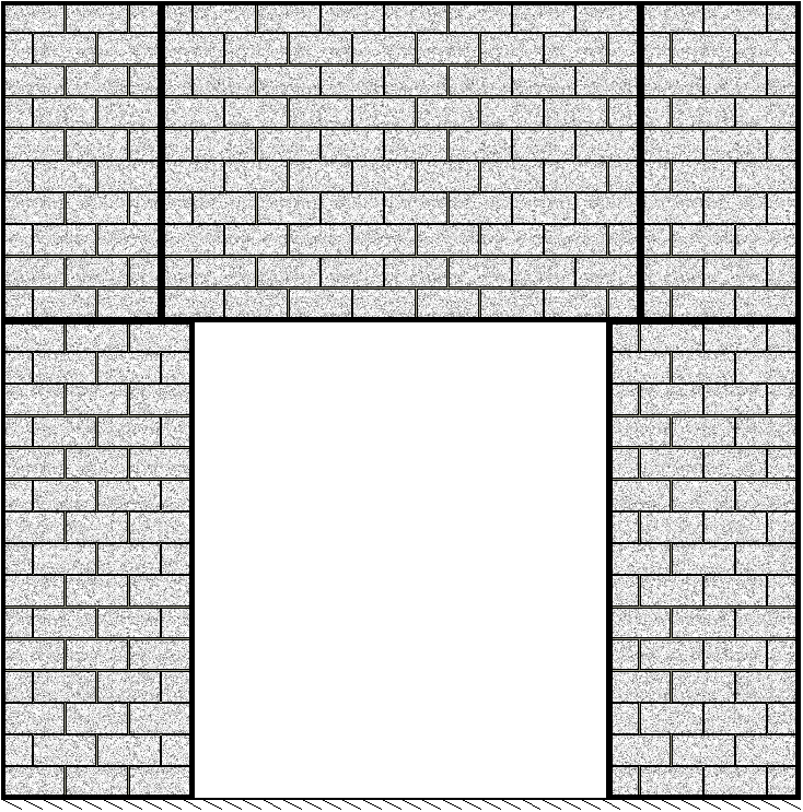 Figure 21: Movement joint with offset placed on both sides of an opening
Modifying an Existing Movement Joint
Movement joints or individual movement joint segments can be moved using the drawing window (as seen in Figure 22: Moving a movement joint segment using the drawing window) by:
- Hovering the mouse over the movement joint and holding down the SHIFT key.
- When the mouse cursor changes to
 , left click and drag the movement joint to its desired location.
 - Release the left mouse button to place the movement joint in its new location.
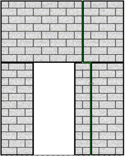

Figure 22: Moving a movement joint segment using the drawing window
Deleting a Movement Joint
Movement joints cannot be deleted in the drawing window. To delete a movement joint, click the Delete Movement Joint button found in the input window. Refer to Figure 31: Deleting a movement joint to locate the Delete Movement Joint button.
Input Window Interface
Using the input window allows movement joints to be created and modified based on exact dimensions, rather than snapping everything to the nearest modular corner of a masonry unit.
Creating a New Movement Joint
To create a new movement joint, press the Add Movement Joint button found at the bottom of the input window, seen in Figure 23: Adding a movement joint using the input window.
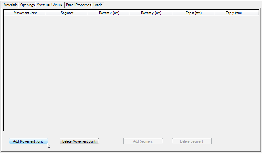 Figure 23: Adding a movement joint using the input window
Pressing the Add Movement Joint button will automatically place a movement joint at the horizontal centre of a shearline. For example, if a shearline is 3000 mm long, the movement joint will be placed at 1500 mm as seen in Figure 24: Movement joint placed at the centre of a shearline.
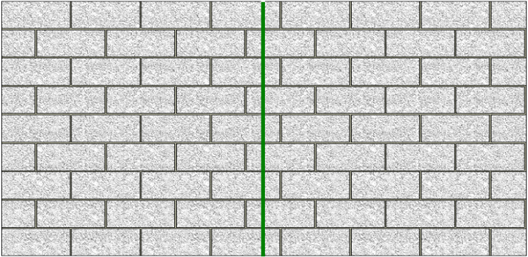 Figure 24: Movement joint placed at the centre of a shearline
Creating a Movement Joint Offset
It can sometimes be useful to create a movement joint that has a horizontal offset along the top of an opening. A movement joint offset can be created through the following steps:
- Select the movement joint in the input window by clicking on it.
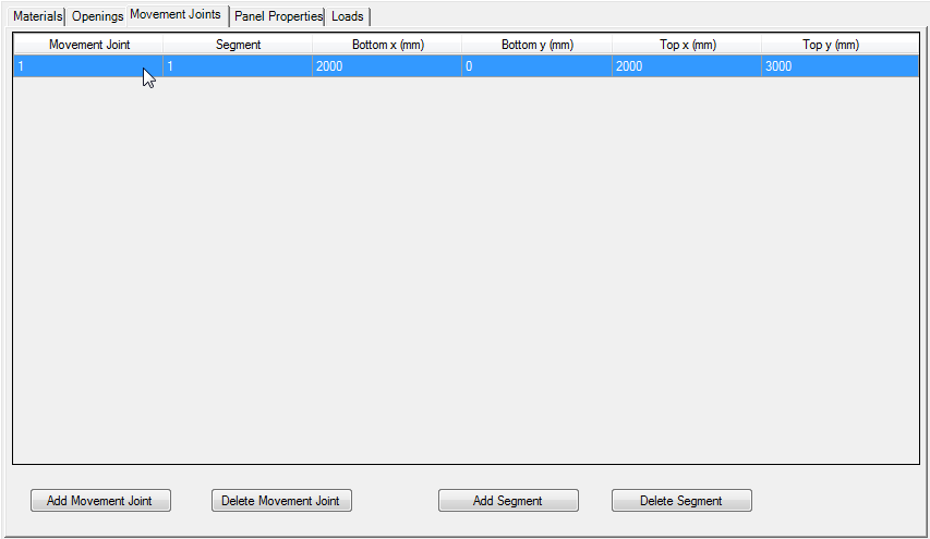 Figure 25: Selecting a movement joint within the input window
- Click the Add Segment button to divide the movement joint into 2 segments of equal length.
 Figure 26: Movement joint as seen in the input window after clicking “Add Segment”
- Select either the bottom y coordinate of the top segment or the top y coordinate of the bottom segment and change this value to the desired height of the offset.
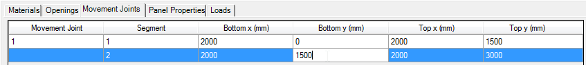 Figure 27: Editing the bottom y coordinate of segment 2
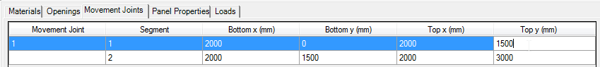 Figure 28: Editing the top y coordinate of segment 1
- Edit either the bottom or top x coordinate of a segment to move it.
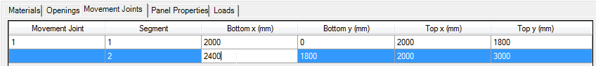 Figure 29: Editing the x coordinate of the segment that is to be offset
Changes made in the input window are automatically shown in the drawing window.
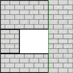
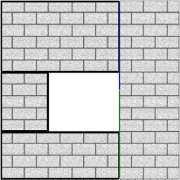
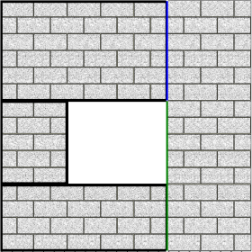
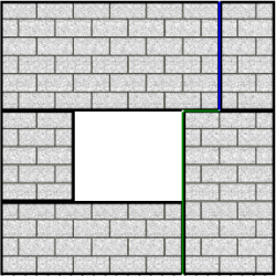
Figure 30: Movement joint offset created using steps 1 through 4, shown above
Modifying an Existing Movement Joint
To make changes to an existing movement joint using the input window, users can change any of the displayed values.
Deleting a Movement Joint
A movement joint can be removed using the input window by clicking the Delete Movement Joint button. Note: If any segment is selected, the entire movement joint will be deleted once the Delete Movement Joint button is pressed.
 Figure 31: Deleting a movement joint
Movement Joint Restrictions
Movement joints cannot intersect openings and movement joint offsets cannot occur within the height of an opening (Figure 32: Invalid movement joint offset location).
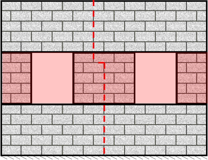 Figure 32: Invalid movement joint offset location
Panel Properties Tab
Once shearline dimensions have been entered, the Panel Properties tab (Figure 33: Panel properties tab) will be made available.
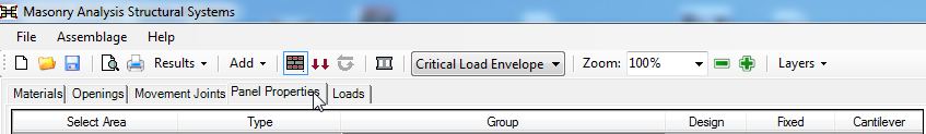 Figure 33: Panel properties tab
The Panel Properties tab serves several important functions for shearline design:
- Users can select different piers on the list to visually identify them in the shearline.
- Different group properties can be assigned to each wall panel.
- Users can select individual piers to be designed.
- The end fixity of each pier can be specified as “Fixed” or “Cantilever”
Selecting Parts of a Shearline
Using the Select Area column is the easiest way for users to see the relationship between piers in a shearline. To highlight an area of a shearline, simply click anywhere within the white cell under the Select Area column (see Figure 34: Selecting parts of a shearline). Panels, Piers, Parent Piers and Strips can all be selected.
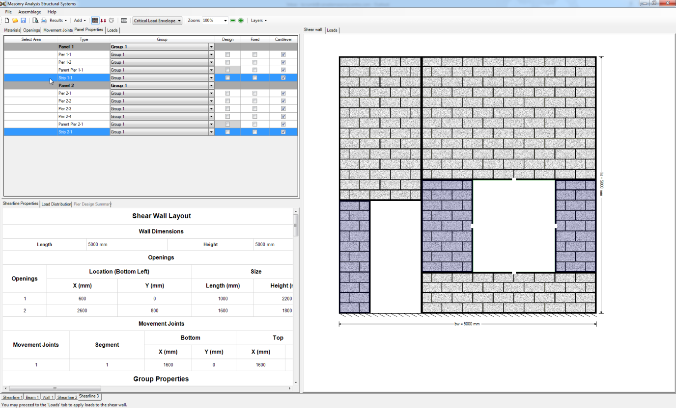 Figure 34: Selecting parts of a shearline
Multiple areas can be selected by clicking the Select Area cell while holding the CTRL key. If two areas are selected while holding the SHIFT key, all of the areas in between them will also be selected. Any number of areas in a shearline can be selected at a time.
Group Properties
To assign a different group to a wall panel, click on any drop-down menu within that panel to see the list of available groups as seen in Figure 35: Drop down menu of available Group Properties. Only Group 1 is available by default.
 Figure 35: Drop down menu of available Group Properties
For more information on Group Properties, click here.
Selecting Piers for Design
The Design selection check box can be found to the right of the Group column in the Panel Properties tab, as shown below in Figure 36: Selecting pier 1-1 to be designed. MASS™ will distribute loads to all piers but only designs piers that are specified by the user.
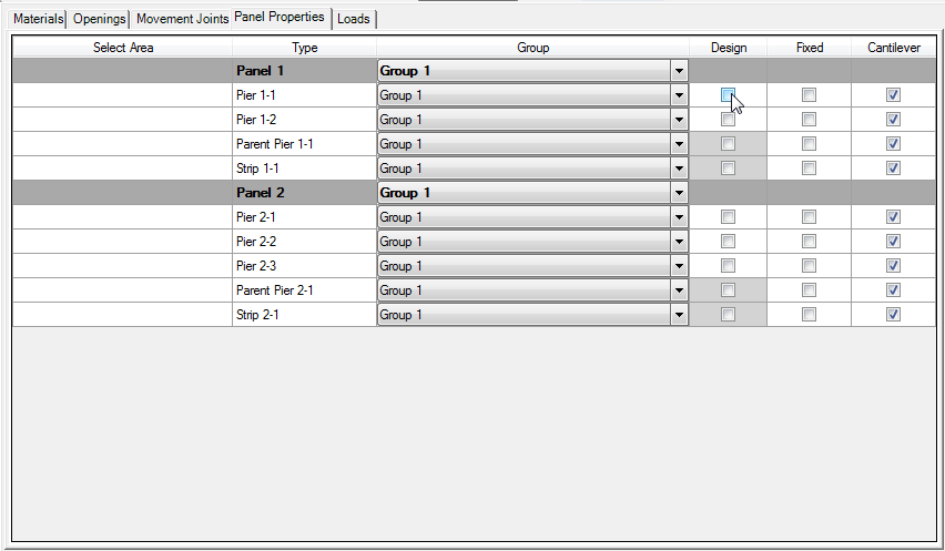 Figure 36: Selecting pier 1-1 to be designed
When a pier is selected, a pier tab is immediately created and can be seen at the bottom of the screen. At least one pier needs to be selected to perform a design.
 Figure 37: Selecting piers for design in the input window
![]() Figure 38: Pier tabs created as piers are selected for design
Figure 38: Pier tabs created as piers are selected for design
When a pier is selected for design, its block size and strength are considered when determining the units used for its panel. Any piers that are not selected for design will be ignored when designing the shearline.
For more information on the shearline design procedure, refer to the Shearline Design Strategy page.
Specifying Pier Fixity
It is important to look at each pier and specify whether its behavior resembles that of a cantilever or fixed pier, illustrated below in Figure 39: Cantilever and fixed pier behaviour. Note: Fixed piers are only fixed at the top from rotation and can still translate laterally.
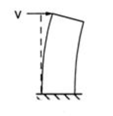
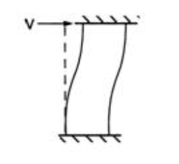 Figure 39: Cantilever and fixed pier behaviour
The fixed support condition is typically applied to a pier where there is a relatively rigid masonry portion above the pier preventing the pier’s rotation, as illustrated below in Figure 40: Highlighted piers that would behave as a) cantilevered and b) fixed. This support condition is selected at the discretion of the user.
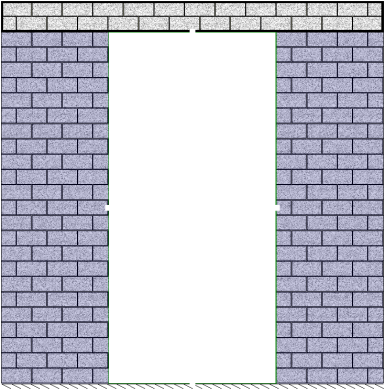
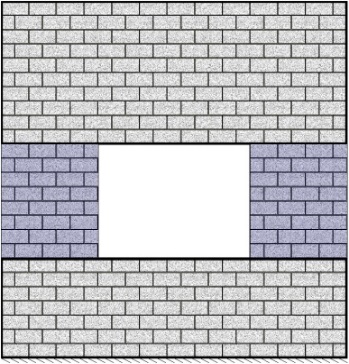 Figure 40: Highlighted piers that would behave as a) cantilevered and b) fixed
To change the top end fixities of individual piers, left click the check boxes to select an appropriate fixity. Only one fixity can be selected for each pier. By default, the end fixity is set to cantilever for each pier, parent pier and strip. When one pier’s end fixity is selected, the other is automatically deselected.
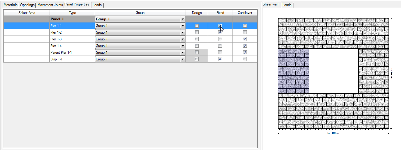 Figure 41: Changing the end fixity of Pier 1-1
Loads Input
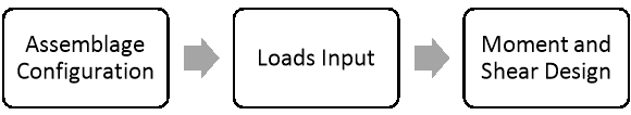
Loads Input is the second step in developing a shearline design. This step allows the user to enter the loads that are applied to the shearline. Loads are applied in a similar manner to other assemblage types:
- Click the Loads Input button or the Loads tab
- Choose the Importance Category that is to be used for all designed piers (low, normal, high, post-disaster)
- Click on Add Load
- Enter in load properties (name, type, distribution, unfactored magnitude and units)
- Enter in self-weight properties (include self-weight from masonry above, Percent grouted)
Loads Input
There are two ways to begin the loads input design step: click on the Loads Input button or the Loads tab. Notice that when performing the loads input design step, the Loads Input button is outlined in blue, as shown in Figure 42: Loads input window. Upon moving into the load inputs design step, the program automatically displays to the load drawing in the Loads tab in the right window.
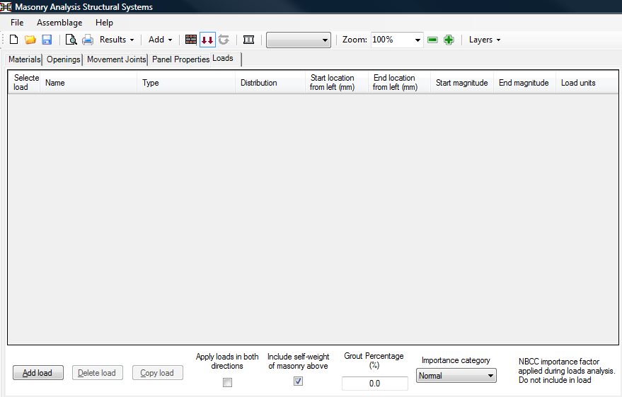
Importance Category
The importance category is selected using the drop-down box under the heading Importance category, shown in Figure 42: Loads input window. For more information, refer to the Loads Input section.
Load Properties
To add a load, click on the Add Load button shown in Figure 43: Changing the load type in the loads input window. For more information on adding, copying, and deleting loads, refer to the Loads Input section.
The program allows for the selection of the following loads for the shearline assemblageWhen walls, shear walls, columns and beams are spoken of in terms of the masonry engineering, they are referred to as assemblages. The areas of the program treating each of these are called modules. In MASS Version 1.1, there are only three modules: beam, wall, and shear wall.: dead, live, snow, wind, lateral earth, earthquake, storage, controlled fluid, and vertical soil. These can be selected using the drop-down box found under the ‘Type’ column.
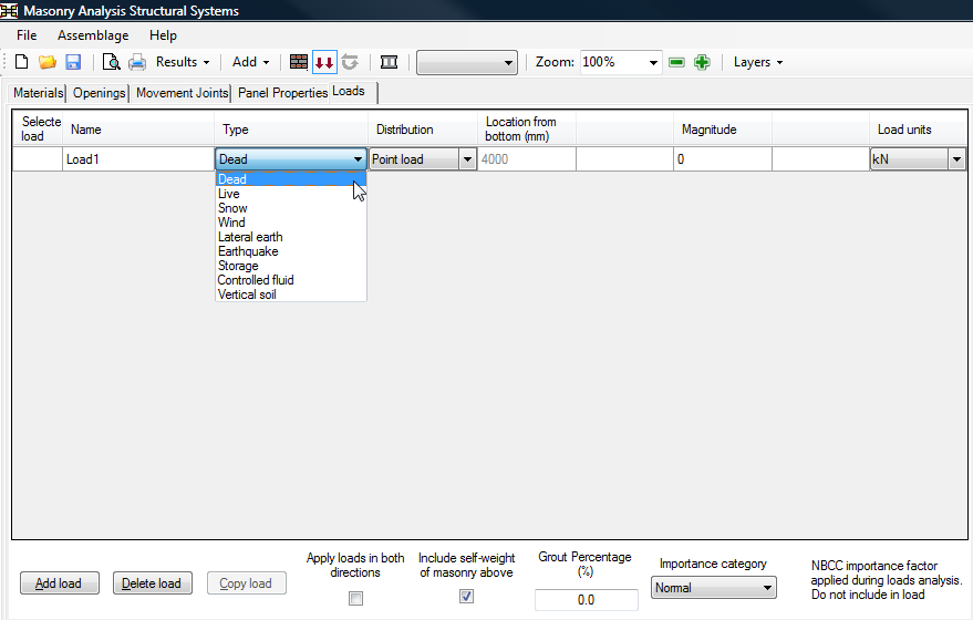 Figure 43: Changing the load type in the loads input window
Similarly to choosing a load type, users can choose the load distribution usiIn MASS Version 1.1, the load distribution defines the shape of the load to be applied to the assemblage (point load, axial load, line load, moment).ng the drop-down box found under the Distribution column. Load distributions that can be applied to a shearline include: point loads, line loads, and axial loads.
A shearline, experiencing an unfactored dead shear (point) load of 500 kN, an unfactored axial dead load of 100 kN at 1200mm from the left edge, an unfactored axial live load of 20 kN at 1200mm from the left edge and a line load from 3800mm to 7000mm from the left edge with a magnitude of 5kN/m is illustrated in Figure 44: Drawing window displaying loads applied to shearline to Figure 46: Multiple loads can be viewed in the drawing window by holding down SHIFT key. Notice the loads are applied at the top of the shearline.
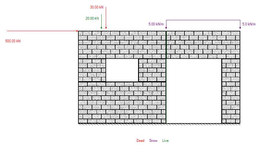 Figure 44: Drawing window displaying loads applied to shearline
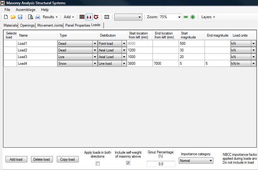 Figure 45: Shearline loads as seen in the input window
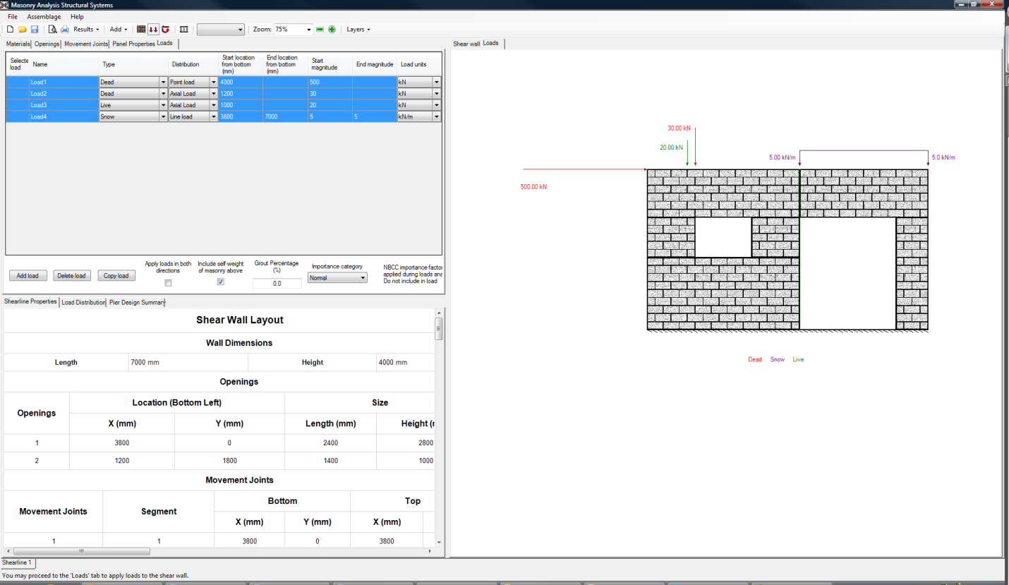 Figure 46: Multiple loads can be viewed in the drawing window by holding down SHIFT key adn clicking on them in the input window
Note: According to MASS sign convention, a west-to-east load is considered a positive load, as is a downward axial load. A moment applied in the clockwise direction is considered a positive moment.
The units of the load can be specified using one of the following units (kN/m, N/m, lb/ft, or kip/ft) simply by selecting the drop-down box under the ‘Load units’ column.
Unlike the beam and out-of-plane modules, the percentage of the load sustained is not included in the loads input design step. This is because MASS does not perform any deflection of an assemblage with respect to its centroid. MASS Version 1.1 uses deflection limits to carry out the deflection design of beams and walls. The limit for beam deflection is L/480 (CSA S304.1-14: 11.4.5), or a maximum total deflection input by users; the limit for out-of-plane wall deflection varies from span/180 to span/360 (CSA S304.1-14: 10.14.3), or a maximum total deflection input by users. The program includes the effects of slenderness (deflection due to deflection) for deflection calculations of out-of-plane walls. calculations for a shearline.
A specific applied load can be viewed under the Loads tab by clicking on Selected Load box of that particular load. Multiple loads can be viewed by holding down SHIFT key, and selecting the loads to be displayed. Figure 46: Multiple loads can be viewed in the drawing window by holding down SHIFT key shows four selected applied loads that are displayed in the Loads tab. The applied loads that are being displayed are outlined in blue in the input table. In the loads drawing, the load colours correspond to the load types. For more information, refer to the Loads Input section.
Critical Load Envelope
Loads applied to a shearline are distributed and applied to each pier unfactored. The critical load envelope for each pier is determined individually and can be seen clicking on the pier tab. For more information, refer to the Loads Input section.
Self-Weight of Masonry Above
The importance category of a building (2020 NBC: low, normal, high, and post-disaster) takes into account the consequences of failure related to the limit state and the use and occupancy of the building. These categories are used to limit the risk of injury of a person, in or adjacent to the building, due to structural failure caused by loads bearing on the building elements that exceed their load-bearing capacity. MASS Version 1.1 uses normal importance category, unless users selects a different one.The Include self-weight of masonry above check-box as well as a field where users can enter the Grout Percentage (%) can be found at the bottom of the input window. The self-weight of masonry above is included in the load calculations by default. Uncheck the box to exclude the self-weight of the assemblage. When walls, shear walls, columns and beams are spoken of in terms of the masonry engineering, they are referred to as assemblages. The areas of the program treating each of these are called modules. In MASS Version 1.1, there are only three modules: beam, wall, and shear wall. check-off the Include self-weight of masonry above check-box, as shown in Figure 47: “Include Self-weight” check box within the input window.
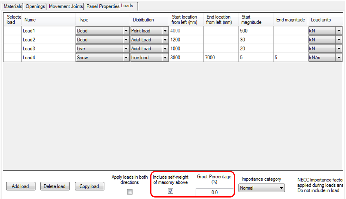 Figure 47: “Include Self-weight” check box within the input window
The self-weight of masonry above is a function of the masonry unit size, density and the grout percentage. By default, the Grout Percentage (%) value is 0%.
The self-weight from masonry above refers to self-weight load generated by piers that lie above the piers being designed. The self-weight of each piers being designed is calculated as a separate value within each pier tab. Since there can be sections of a shearline that are not designed and these self-weight values are needed before the design has begun, users must first estimate and then confirm the percentage of grouted cells in the wall in order to determine loads that are sent to the individual pier. There can be several piers within a shearline. tabs.
In the example shown below in Figure 48, pier 1-6 is being considered for design. The self-weight is calculated automatically for the pier itself, shaded in yellow. This load is handled within the pier There can be several piers within a shearline. tab and is updated after performing moment and shear design with the actual grouting configuration taken into account. The rest of the shearline shaded in green, uses the Grout Percentage (%) value when calculating the amount of self-weight axial load distributed to pier Area of masonry within a shearline containing no openings. There can be several piers within a shearline. 1-6. In this case, only self-weight from pier. There can be several piers within a shearline. 1-5 is applied to pier. There can be several piers within a shearline. 1-6. For more information on how vertical loads are distributed, refer to the Pier Generation page.
When considering pier 1-8 for design, the axial load from pier. There can be several piers within a shearline. 1-6 is based on the Grout Percentage (%) value and the self-weight of pier 1-8 is updated after Moment and Shear Design have been performed.
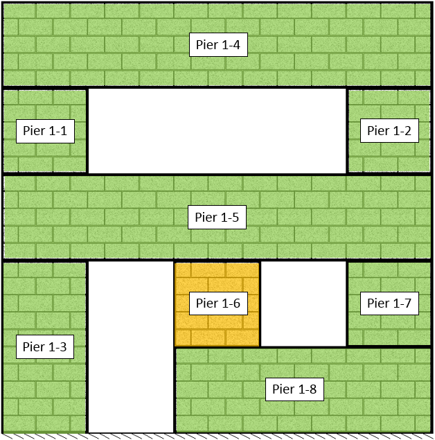 Figure 48: When designing Pier 1-6, self-weight of pier shaded in yellow and self-weight of masonry above shaded in green
Apply Loads in Both Directions
To design a shearline in the reverse direction check-on the Apply loads in both directions check-box as seen in Figure 49: Apply loads in both directions check box in the loads input window. By default, shearlines are not designed in both directions.
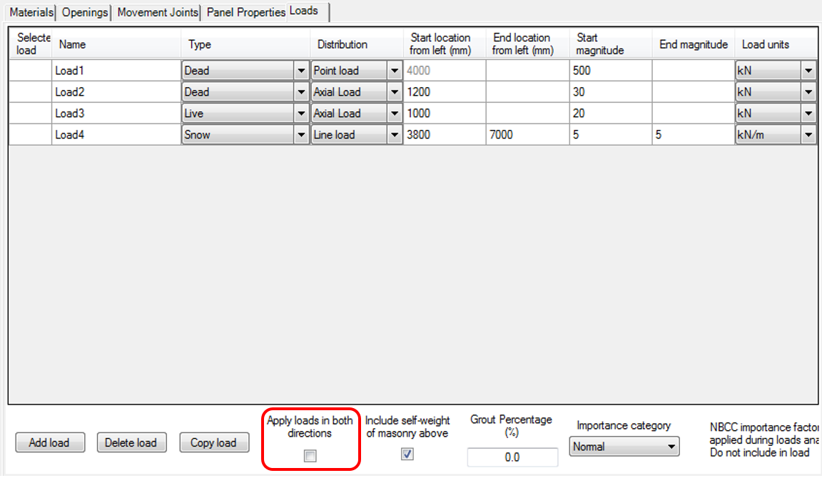 Figure 49: Apply loads in both directions check box in the loads input window
Designing a shearline in both directions does not have any effect on the load distribution. Selecting the option of designing a wall in both directions sends this instruction to the individual pier tabs.
For information on designing a pier or shear wall in both directions, refer to the Loads Input section.
Moment and Shear Design
Moment and shear design is the third and final step in developing a shearline design. It involves the simultaneous management of several pier designs while updating vertical and horizontal load distributions. MASS™ designs each pier for moment and shear, then selects a unit size and strength based on the critical pier design results for each group. For more information, refer to the Shearline Design Strategy page.
In order to run the moment and shear design:
- Click on the Moment and Shear Design button, as shown below in Figure 50: Moment and Shear Design Button.
 Figure 50: Moment and Shear Design Button
Notice that when performing the moment and shear design step, the Moment and Shear Design button is outlined in blue. When in this stage, any changed made to the shearline geometry, masonry unit properties or reinforcement properties will result in a complete redesign of all piers.
Interpreting Design Results
Upon the completion of the moment and shear design step, the Pier Design Summary tab (Figure 51: Pier Design Summary) shows users a sample of relevant information related to each of the piers being designed.
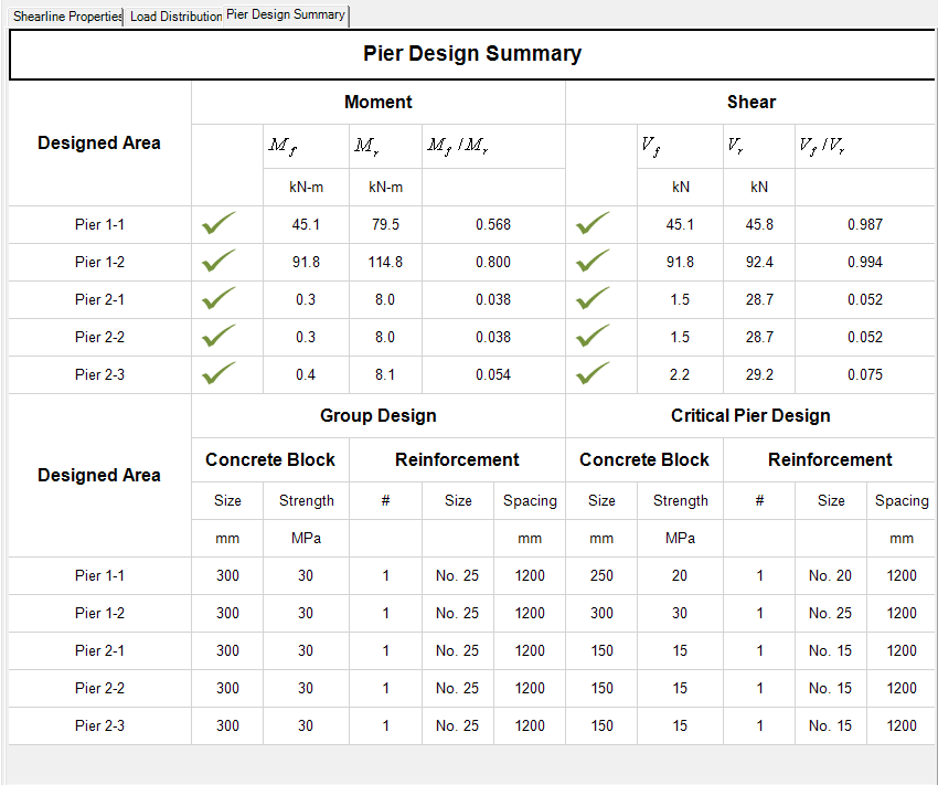 Figure 51: Pier Design Summary
This Pier Design Summary results tab is composed of two sections: the moment and shear summary and the pier design summary.
Both sections are designed to give users an overview of a piers’ factored resistance compared to the total factored loading. In the top table, the values for Mf, Mr, Mf/Mr, Vf, Vr and Vf/Vr are listed in order to give a numerical representation while the group and critical pier design columns are intended to give a more conceptual representation.
Users can quickly look at the Mf/Mr or Vf/Vr ratios to see which piers have a factored resistance closest to their loading requirements. In Figure 52: Mf/Mr and Vf/Vr ratios, Pier 1-4 is closest to being at full moment capacity while Pier 1-2 is closest to being at full shear capacity.
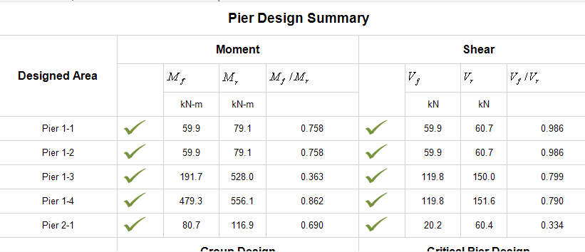 Figure 52: Mf/Mr and Vf/Vr ratios
Similarly, users can look at the critical pier design results to see which piers governed the shearline design. The Critical Pier Design column shows users what minimum design is allowable for the pier and the Group Design column shows what was actually placed in the wall. This is useful to show users when the design of a wall is based on a single element. Figure 53: Critical Pier Designs shows a shearline where most of the critical pier designs require a 150mm, 15MPa unit while Pier 2-1 requires a 200mm, 25MPa unit. The entire shearline is designed using the larger, governing block size and strength although it is only required for one of the piers being designed.
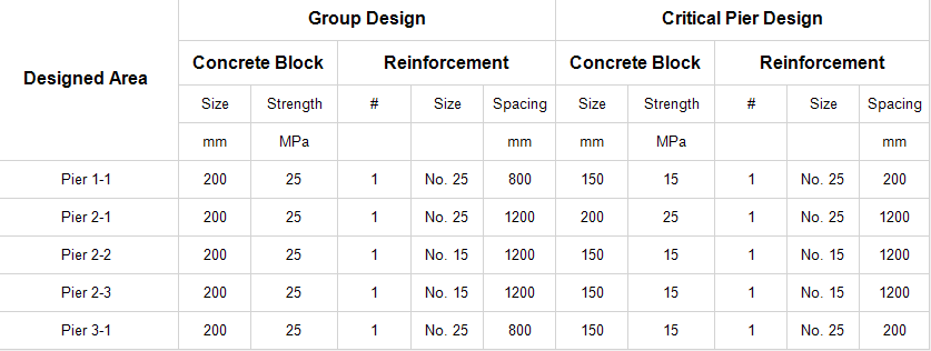 Figure 53: Critical Pier Designs
Unsuccessful Design Results
Shearline designs can fail for several reasons. Figure 54: Unsuccessful shearline design results below shows a shearline with all 5 piers selected for design. The red X’s indicate that a pier has failed one or more areas of design. Piers 1-1, 1-2 and 1-3 all pass for moment but they fail under shear, having a lower Vr compared to their respective Vf value. Pier 2-1 does not pass moment design so a blue dash is shown to the left of the shear design results to indicate that it has not yet been performed.
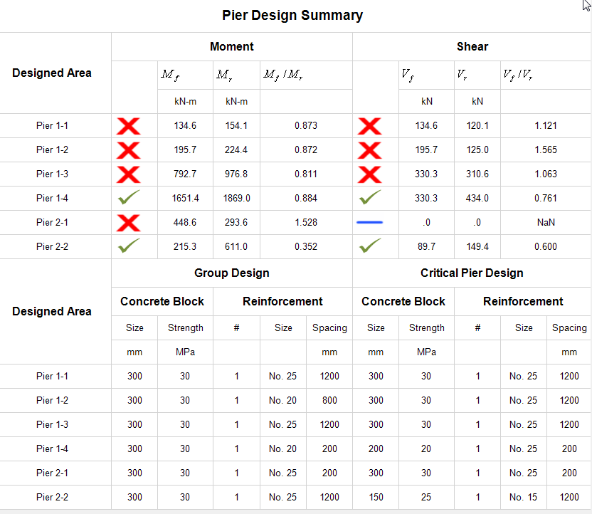 Figure 54: Unsuccessful shearline design results
For critical pier and group design results, users can still see values even though a successful design has not yet been completed. When a shearline does not pass moment or shear design, the last attempted configuration is displayed for each pier. Using the default unit size and unit strength, this will be a 300mm, 30MPa block.
Default Vertical Steel
The vertical steel options for MASS™ have changed in shearline to accommodate the design of several piers. The Vertical Steel input area has been changed to the Default Vertical Steel, as seen below in Figure 55: Vertical Steel Input in Version 2.0 compared to Version 1.1.
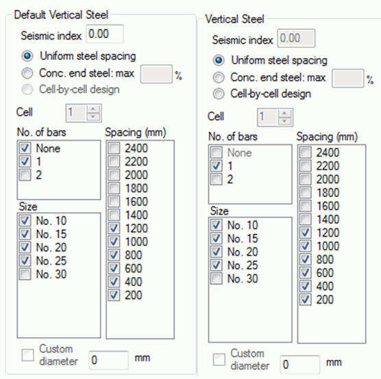 Figure 55: Vertical Steel Input in Shearline compared to Shear walls module
The only difference between the controllers themselves is the removal of the cell-by-cell design option. The Uniform spacing and Concentrated end steel selections can be universally applied to every pier selected for design.
Horizontal Steel
MASS™ Version 2.0 allows the use of joint reinforcement and bond beams, however the default selections cannot be changed at the shearline level. MASS™ automatically will try to use smallest area of horizontal steel by incrementally increasing the area of joint reinforcement and bond beams in a shear wall. For more on this, refer to the Shearline Design Strategy page.
Users can check the shear capacity of a wall with a different configuration of horizontal steel by using the Copy function to quickly create a replica pier that runs independently from the rest of the shearline. The copied pier has no restrictions on the user interface so users are free to analyze their wall using any configuration of horizontal steel.
Note: changing masonry properties can result in changes to the lateral load distribution which will not be reflected in a copied pier tab.
Other considerations
Upon the successful completion of the Moment and Shear Design step, the shearline design is complete.
Warning: Detailing work is left up to the designer. MASS™ does not account for splice lengths, development length, epoxy coating, etc.
Continue Reading: Load Distribution
Was this post helpful?