

Multi-Storey Design Strategy
Outlining the process of using the shear wall element design process and how it is applied to a multi-storey design
This page will explain the design strategy and approach used by the multi-storey shear wall module to come up with a final design based on the results from each individual shear wall element. The explanation first reviews the overall requirements for multi-storey shear wall design and provides some basic background explanations for how individual shear wall elements are designed. The full design process is then laid out in the form of five distinct stages – many of which are performed several times in the design of a single wall.
Multi-Storey Design Requirements
When a multi-storey shear wall is designed using MASS, the goal of the software is such that the end result meets the following two sets of conditions:
Capacity Design: All design criteria from each individual element is satisfied (shear wall has adequate capacity and satisfied all clauses checked by the software). This is referred to within the design strategy article as the Capacity Design stage (click here to jump ahead to that section).
Group Equalization – : Shear wall element designs part of the same Group are designed with the same cross sectional properties, sharing the same masonry unit, grouting pattern, and reinforcement configuration between grouped storeys. This is referred to as the Group Equalization stage. (click here to jump ahead to that section).
Additional requirements are optional and applied as required based on geometry, loading, and seismic inputs:
Structural Irregularities (optional): Shear walls are checked for structural irregularities only for designs where an earthquake type load is applied and the Equivalent Static Force Procedure has been selected in the Seismic tab. This is referred to within the design strategy article as the Structural Irregularities stage (click here to jump ahead to that section).
Drift (optional): Shear walls are designed to not deflect beyond the inter-storey drift limits under load combinations containing an earthquake type load. this is referred to as the Drift stage. (click here to jump ahead to that section).
Ductility (optional): Shear wall designs containing a plastic hinge region are required by the CSA Standards to satisfy ductility requirements. This is referred to as the Ductility stage (click here to jump ahead to that section).
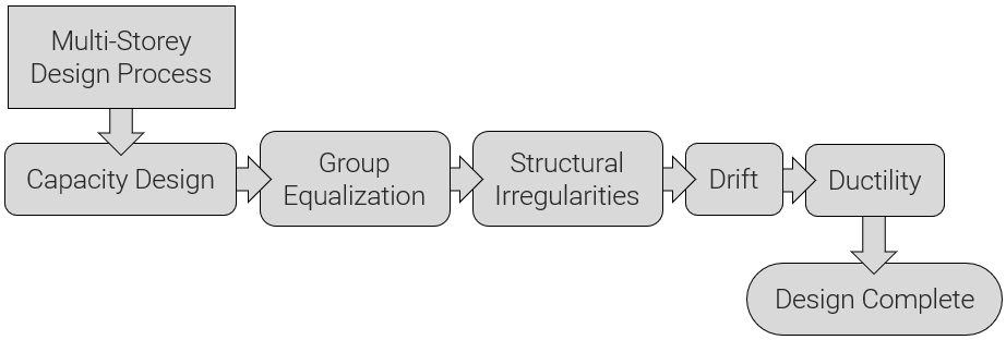
These stages are laid out in the simplified flowchart, pictured below:
Successful Multi-Storey shear wall results indicate to the user that MASS has checked and designed based on these requirements as they are applicable.
Shear Wall Element Design Review
A full breakdown of how the MASS software handles the design of an individual shear wall element can be found here on the shear wall design strategy page. Only the aspects referenced further down this page are summarized below.
Design Scope
Individual shear wall elements are designed for moment and shear based on the unfactored loads that have been applied by the user. Similar to how the shear wall design process is used for a MASS shearline, the results from each element are simply passed along from the element design results to be reported by the multi-storey module. While the load distribution is handled at the multi-storey level, all of the engineering calculations having to do with a shear wall’s resistance are determined at the element level.
Individual shear walls are designed for:
- Factored Bending Moment
- Factored Shear
- Minimum Steel – ensuring that the limits outlined in the CSA Standards are satisfied.
Currently, transverse shear between a shear all web and flange or boundary element is not checked by MASS and must be verified manually. At the end of the day, the MASS software is simply a tool that the engineers uses along with their own professional judgement.
Iterating through Cross Sections
The approach taken by MASS to design any assemblage is to apply all possible factored combinations and check to see if the wall passes, starting with the smallest, weakest masonry unit with the least amount of reinforcement. If any type of failure is triggered, the program stops designing and moved to a larger cross section, incrementally increasing any of the variable properties and starting again.
The order in which these properties are incremented is summarized in the figure below and explained on the shear wall design strategy page in further detail.
Moment Design Review
The following figure shows the hierarchy of incremented properties affecting moment design at a glance:
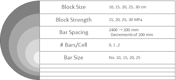
The innermost properties are incrementally increased before the outermost ones are changed. For example, MASS will attempt a design with larger vertical reinforcing bars before changing the bar spacing or masonry block properties such as size and strength.
Shear Design Review
The following figure shows the hierarchy of incremented properties affecting shear design at a glance:

For each of these diagrams, the innermost properties are incremented first before moving outward to the larger changes. For example, increasing the size of rebar used in a design is considered a smaller change in comparison to increasing the masonry unit thickness.
Note: more details are available on the shear wall design strategy page which are specific to designing using concentrated end steel mode as well as cell-by-cell design.
The design process outlined in the subsequent section will explain the method used by MASS to end up with a multi-storey design where both of these requirements are satisfied for the entire height of the wall.
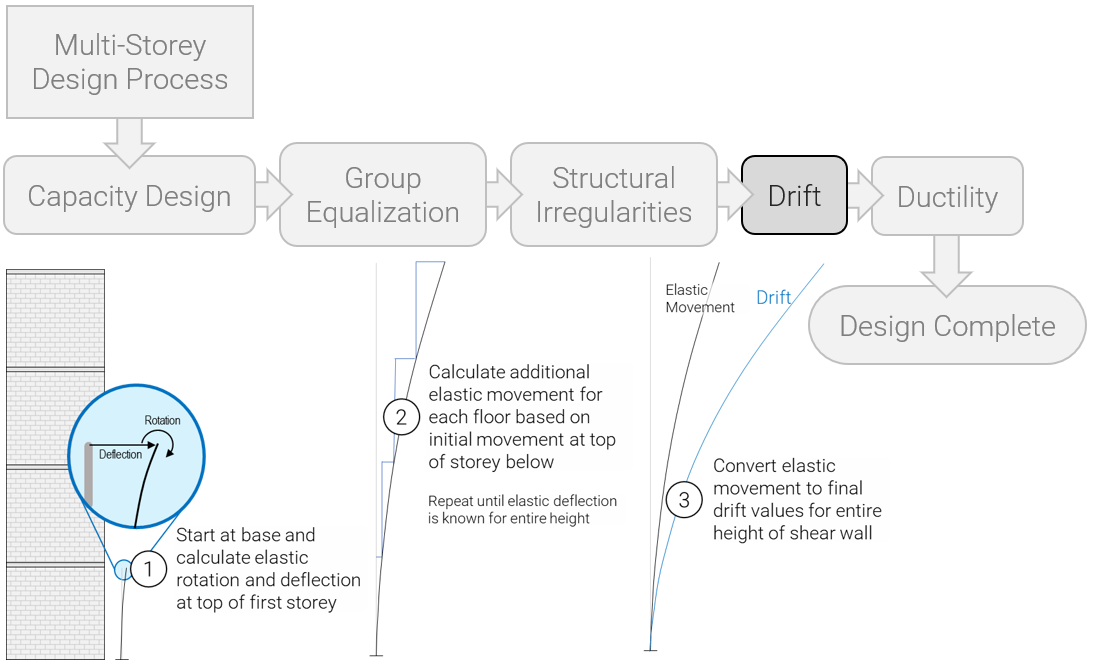
Multi-Storey Design Process
MASS coordinates the designs of multiple shear wall elements in stages that move in two directions: top-to-bottom and then bottom-to-top
The first is moving from top to bottom after the initial multi-storey load distribution in order to accurately apply the self-weight of all floors resting above during the Capacity Design stage. The top-to-bottom approach is also used for the Group Equalization stage where different designs are synced to using the same cross section.
for each design and the second starts at the base and works upward in order to determine drift, design for structural irregularities, as well as satisfy the ductility verification when needed.
These various stages that MASS moves through can be summarized using the basic flowchart shown below:
Note: This process flowchart has been simplified in an attempt to make the design process more accessible and easily digestible. A more detailed flowchart can be seen by clicking here.
The subsections below outline what exactly is done during each stage. It describes how MASS navigates between and handles successful or failing results.
Stage 1: Capacity Design
It is the Capacity Design deign stage where each element is designed for moment, shear, and all other shear wall element considerations performed by MASS.
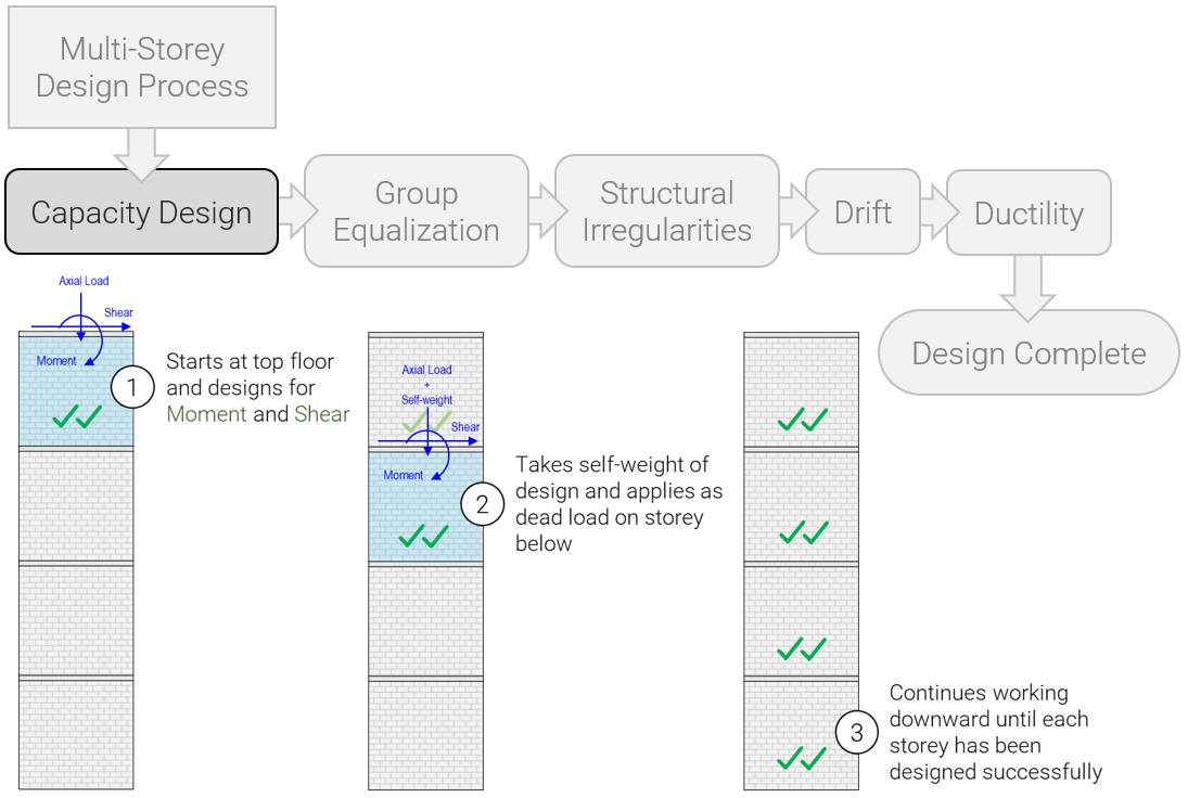
Since the moment resistance, shear resistance, and seismic drift is a function of axial loading, self-weight must be kept accurate throughout the design process.
Top to Bottom Approach
This stage starts at the top shear wall element and moves downward to ensure that axial loads from self-weight of elements above are kept up to date based on wall thicknesses and grouting patterns that change as cross sectional properties are iterated.
Successful Designs
Once a successful design is found for any storey, MASS will move on to designing the storey beneath until the bottom storey has been designed. If a storey design is changed again for any reason later on in the design process, the software will automatically complete another round of the capacity design stage updating the designs for all storeys beneath to take any potential effects of the added self-weight into account for floors beneath.
Failing Designs
If a design fails for a shear wall element at one storey, MASS will save the failed results and continue through the capacity design stage until the bottom storey has been designed – pass or fail. At that point, the software stops all subsequent processes and presents the results to the user. It is for this reason why different properties may be shown within the same property group within a multi-storey design. The Group Equalization stage which would come next if the designs were successful is where this is addressed.
Stage 2: Group Equalization
The Group Equalization stage is the point of the design which ensures that the same cross section is used for all storey designs within the same property group. Click here for more information on property groups.
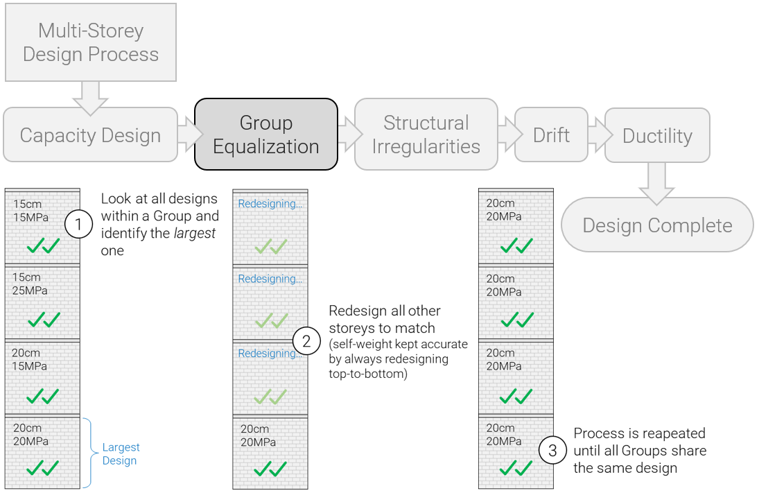
Top to Bottom Approach
Once the capacity design has been successfully completed, MASS then starts at the top storey design and compares it to all other designs that are part of the same group. If there are no “larger” designs that are compared against then the storey design remains the same. If another floor is found to consist of a “larger” cross section then the storey being examined is changed to match the “larger” one. The use of quotation marks here is intentional because the manner in which one cross section is compared to another is more complicated than just looking at unit size or grout present.
Comparing Designs
When looking at a variety of design results, it can be difficult to select the one that will satisfy all floors at first glance. The way this is handled within MASS is by looking at the process in which the software cycles through cross sectional properties in a sequential order. Rather than step into the murky waters of comparing actual properties, the way in which cross sections are compared is by looking at how far they have incremented through the design loop. As covered earlier, each shear wall element starts with the smallest, weakest masonry unit with the smallest, largest spaced rebar before failing and incrementing to the next cross section to be tested. Since each storey has already reached a successful moment and shear design before entering the Group Equalization stage, each storey has failed a different number of times before arriving at their result. The “largest” design among them is the shear wall that had to fail the most attempts beforehand to get to that successful state.
Comparison Specifics
Feel free to skip ahead if the exact numerical method in which storeys are compared doesn’t pitch your tent. As long as it is understood that MASS will automatically synchronize the designs within a property group during multi-storey shear wall design, there is not much else to be gained by diving into the specifics.
MASS designates the governing, or “largest”, design based on which storey is the furthest along the design algorithm for that group. For example, if the choice is between a shear wall that was designed successfully after running through 15% of the algorithm and another that didn’t pass until getting through 55% of that same loop, the first shear wall is updated and checked using the properties from the second one.
This percentage is determined from the ratio of how many possible cross sectional combinations remain in the design loop to the initial number of cross sections before design began, multiplied by 100%. As a design is performed, this will start at 0% and work upward. A result of 100% can mean that either the very last attempted design yielded a successful result or the more likely instance where the design ended up failing.
MASS calculates an initial theoretical maximum total number of cross section combination based on the user check box selections. For example, if there are five unit sizes and 4 strengths for each, there are 20 possibly masonry units that can be used for design. The number of total cross sections greatly increases when the options of horizontal and vertical steel are added. A shear wall element with only the default selections enabled has a total of just under 14,000 possible combinations to evaluate!
As the design progresses, this number of remaining sections is reduced and can jump in large increments. For example, a design may require a 20cm masonry unit for moment which will also rule out all of the possibilities for shear design results using the smaller 10cm and 15cm unit sizes.
For more information on how this is handled internally within MASS, please feel free to contact MASS support.
Stage 3: Structural Irregularities
MASS checks against structural irregularities that can be detected by examining a single wall. As a result, there are many irregularity types that are outside the scope of MASS and what the software might identify as an irregularity for the shear wall may not apply when the storey is examined as a whole.
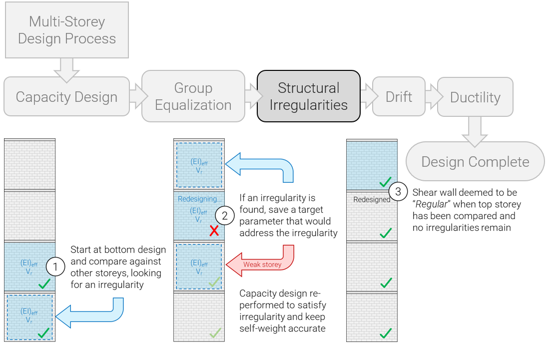
The software starts at the base of the wall where the governing design is likely located and works upward from there. There are two parts to how MASS handles structural irregularities: detection and design. In the first phase, MASS simply evaluates the structure upon successful completion of the Group Equalization stage to determine whether any irregularities exist. The second phase involved designing the shear wall further to return back to the “Regular” designation.
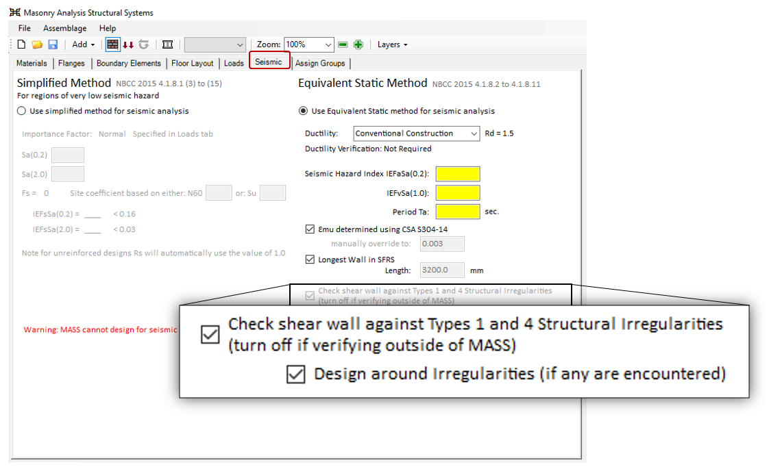
The option to design the multi-storey shear wall to be “regular” can be turned off in the seismic tab and is explained in the section beneath the description of each irregularity.
Detecting an Irregularity
In an effort to determine whether a design can be given the designation of “Regular”, MASS performs checks for the following irregularities starting at the bottom of the wall.
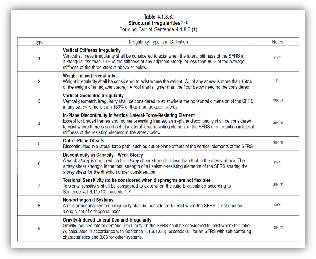
Type 1: Vertical Stiffness
MASS starts by examining the effective bending stiffness of that storey and compares it to adjacent storeys to ensure that it is within 80%, preventing designs where there is a large jump in stiffness from storey to storey. Once checking the 4th floor or higher, the stiffness is compared to 70% of the average three floors below. When further than three floors from the top storey design, this effective stiffness is also compared against 70% of the average of the three floors above, as per the Type 1 definition in the NBCC:
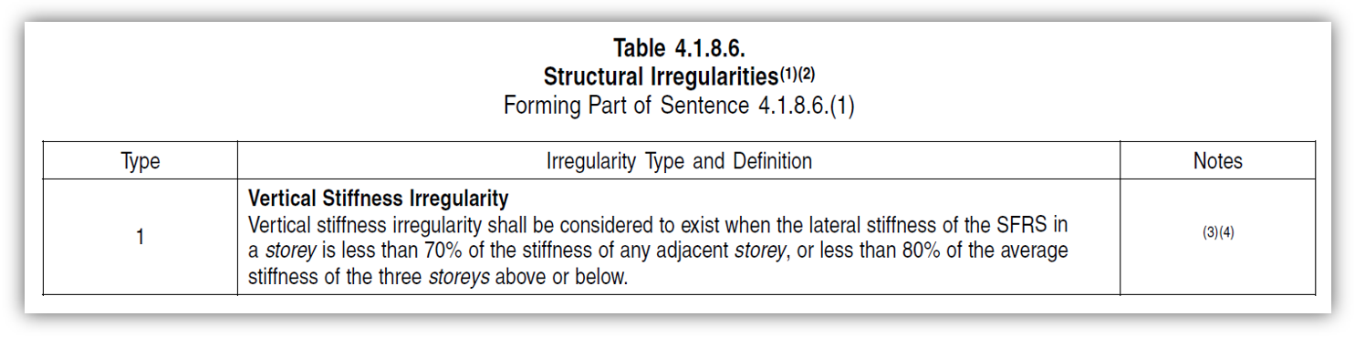
One more thing to note is that the commentaries add the provision where the uncracked stiffness can be relied open instead of the total effective stiffness. MASS checks first based on effective stiffness before the software will check uncracked. Both must be flagged as irregular before a wall is labelled as Type 1 Irregular.
Type 4: In-Plane Discontinuity
While the bulk of a Type 4 irregularity definition does not apply to walls designed within the scope of the multi-storey shear wall module, the latter part of that NBCC section states that a floor cannot be less stiff than the floor above. As a result, this is checked from bottom to top
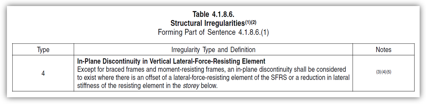
As is the case with Type 1 Irregularities described in the subsection above, MASS will fall back to checking uncracked stiffness before identifying a Type 4 Irregularity on the basis of effective stiffness alone.
Type 6: Discontinuity in Capacity
MASS does not check for Type 6 structural irregularities. In earlier stages within the Version 4.0 development process, the software would identify a reduction comparing the lesser of the diagonal and sliding shear resistances to floors directly above to prevent a “weak storey” scenario. The 2015 NBCC table reference is shown below:
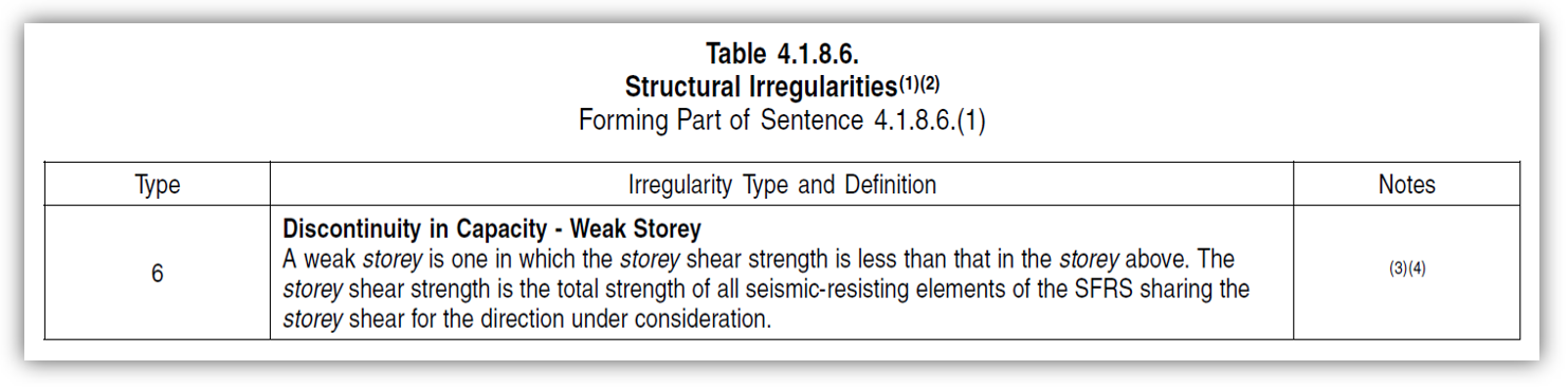
Why does MASS not identify or design around what would seem to be a type 6 irregularity? A separate post covers this topic in more detail – linked here. For reinforced masonry, shear walls are designed to experience a flexural failure mechanism (as opposed to a shear failure mechanism) so the requirements of Type 6 are not applied in these instances.
The only exception to this is the case of multi-storey shear wall designs that employ a squat SFRS and also have a change in cross section between storeys. This post covers that exception in further detail. Note that outputs showing the shear resistances of each storey are still displayed in the seismic tab for user reference in such rare instances.
Other Irregularity Types
In addition to Type 6, Structural Irregularity Types 2, 3, 5, 7, 8, and 9 are not performed by MASS. It was decided early in the development stage that it was not beneficial in flagging these are they are either a function of more than just what can be seen in one wall or outside the scope of what can be designed within MASS.
Once Types 1 and 4 Irregularities have been checked against, the structure is either designed as “regular” for all relevant seismic calculations or a flag is triggered and saved for the irregular storey designs.
Note: Just because a structure is designated as “Regular does not mean that it does not trigger any irregularities checked outside the scope of MASS. Similarly, an irregularity for one shear wall may be offset by the design of other walls with the storey meaning that what the software flags as an irregularity may not actually be present for the storey as a whole. Recall that it is the responsibility of the designer’s engineering judgement to understand the software’s scope and ensure that the design satisfied the applicable codes and standards.
Dealing with Irregularities
There are many design scenarios where irregularities are permitted and introduce added design considerations for the user. By default, MASS will design multi-storey shear walls that do not contain irregularities but it may be the user’s intention in which case the option can be disabled, outlined in the section below.
Designing to be “Regular”
Being regular is something we all strive for in our day to day lives. Why should MASS be any different? MASS offers the user the option to automatically design a multi-storey shear wall to avoid irregularities and be designated as “Regular”. This is enabled by default but can be disabled within the seismic tab.
When this is done, and an irregularity is found, MASS returns to the capacity design stage with the added saved information in the form of “targets”. These are created by the software and stored until these targets have been met further along the design process.
For Types 1 and 4 Irregularities regarding bending and shear stiffnesses, this means that a storey that is found to not be stiff enough will save the minimum value that would have satisfied that irregularity. MASS will then return to the capacity stage but instead of checking only moment and shear, the software will continue incrementing through cross section designs until a section is found that is stiff enough to no long trigger the irregularity. By meeting that target, the next time MASS checks whether there is an irregularity, it will no longer be triggered because there is no longer such a drastic change in stiffness.
For a detected Type 6 Irregularity where there is a storey design with a lower shear resistance than the storey above, MASS will save the resistance from the storey above as the target and return to the capacity design stage. The group properties are then increased according to the design algorithm and in addition to verifying that the diagonal shear and sliding shear resistances are greater than or equal to the factored shear experienced by that storey, MASS also ensures that it meets the saved target value before moving on.
For any designs where the structure is stiffened or strengthened to satisfy an irregularity, the capacity designs for all storeys are updated to ensure accurate self-weight values and if required, the group equalization stage is run again. This can be triggered several times within the process of designing a single shear wall but is handled automatically by MASS. Each time a storey changes, the software will once again attempt to detect any irregularities just to make sure the changes to one part of the structure haven’t created other irregularities elsewhere.
Once the irregularity design stage has been completed, the software will move to determining drift.
Stage 4: Drift
Upon successfully designing each storey and satisfying irregularity requirements as needed, MASS will then calculate the deflection and rotation along the entire height of the shear wall.
To summarize, MASS starts at the base of the wall and calculates the elastic rotation and deflection at the top of the first storey. The software then uses that rotation and carries it through the floor slab to determine the lateral deflection at the base of the the second storey. This process is repeated, working up the height of the shear wall until the elastic movement (deflection and rotation) is known at the top. These elastic movements are then converted to final drift values based on the equation in the National Building Code of Canada.
This is covered in detail for individual shear wall elements here and for multi-storey shear walls on its own dedicated page here. The end result of that process is a drift profile that spans the entire height of the structure.
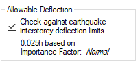
MASS will then check the wall against the applicable drift limits specified by the NBCC which are a function of seismic analysis type and Importance Category.
Satisfying Drift Limits
If the drift profile of a shear wall does not satisfy the NBCC requirements, the design process is ended and the user is shown the failing results. Unlike the Structural Irregularity stage where there are clear targets that can be set to address the failure, MASS does not attempt to continue the design in order to satisfy drift.
Drift limits are shown in the Materials input tab where the limit is shown as well as the importance factor
This option is selected by default but can be disabled for situations where the user has done more comprehensive modelling outside of MASS. Drift will still be calculated and plotted.Once this has been completed, the final stage in designing a multi-storey shear wall is to check Ductility.
Stage 5: Ductility Verification
Once the deflection of the entire multi-storey shear wall has been calculated for each seismic load case, the ductility verification can be performed if required based upon seismic related user inputs. Shear wall elements defer the ductility verification when the element is within a multi-storey shear wall so that the check can be done once for the entire assemblage when all movement and design data is known.
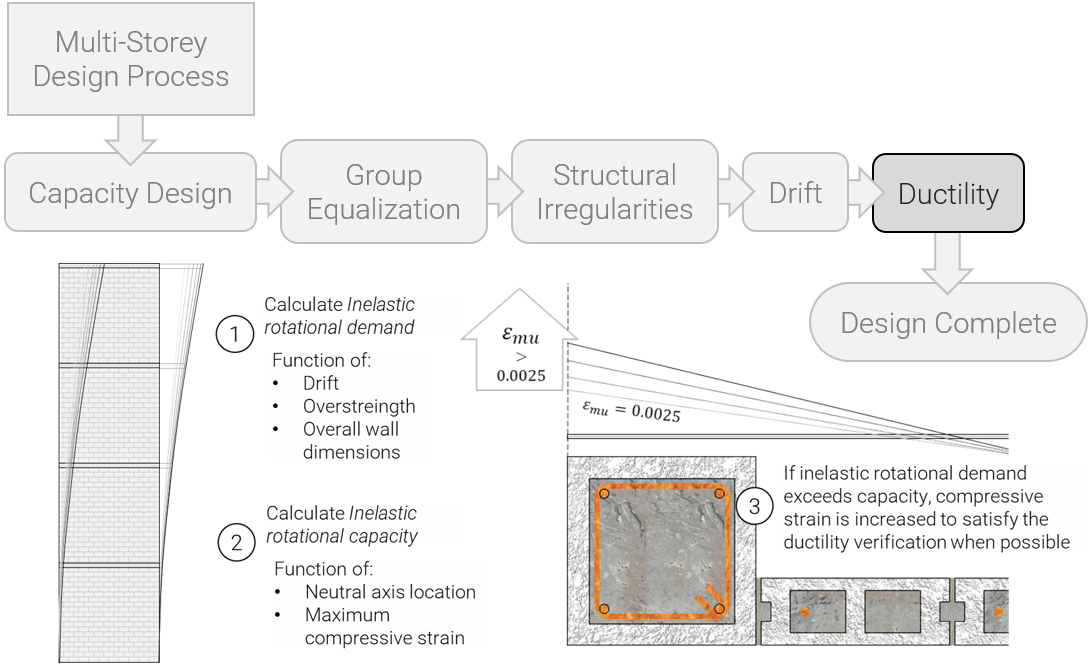
At this time, MASS will simply show the passing or failing results of the ductility verification, without making any additional effort to increase the cross sectional properties of the elements. It is then up to the judgement of the user to assess the possible reasons for failure and decide how to modify the input selections in an effort to find a design that will demonstrate adequate ductility. Shear wall designs not containing boundary elements with tied compression steel are terminated at this point.
Dealing with Inadequate Ductility
When the ductility verification is not successful, all hope is not lost! Designs containing boundary elements on each end of the wall where the reinforcement is tied to not buckle in compression can be further analyzed with higher values of maximum allowable compressive strain, εmu, to try and satisfy a previously failed ductility verification.
Considering higher strains
The first step MASS takes when evaluating this approach is to check whether an increase in strain can possibly be effective in satisfying ductility. The ductility verification is outlined in CSA S304-14: 16.8.8 where the inelastic rotational demand, θid, is compared to and must not exceed the inelastic rotational capacity, θic. Formulas for each are provided by the standard and are also capped by lower and upper limits.
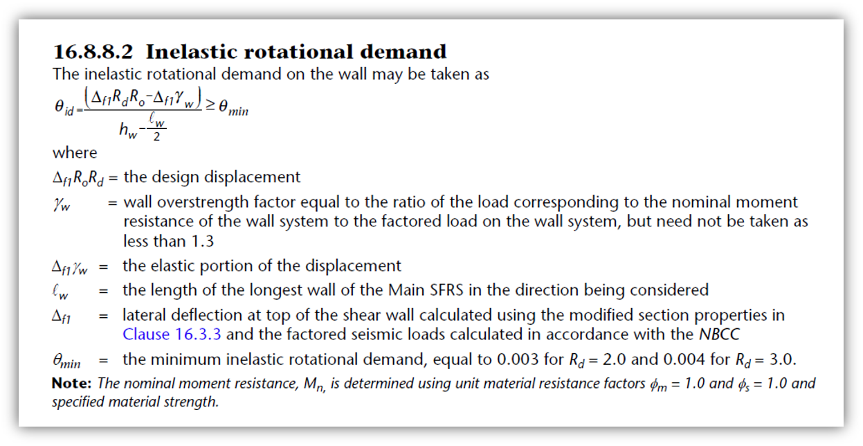

As a result, MASS will attempt to increase εmu enough to satisfy the ductility verification but no higher than the minimum increase required. Strategic increases in εmu can be used to increase a wall’s inelastic rotational capacity with trade-offs and other restrictions that must also be satisfied.
Declaring Failure
Before kicking off the arduous process of re-analyzing the section with higher εmu, MASS first considers the upper limits of θic, which is set by the CSA Standards at 0.025.
If the inelastic rotational demand exceeds that maximum upper limit for capacity, no amount of compressive strain increase will change the fact that the design does not satisfy the ductility verification. In these cases, the software will report the failure to the user and terminate the design process.
Note: MASS will simply stop designing a report the failure, without incrementally designing larger cross sections. This is to allow the user to examine the results and manually make and strategic changes that would improve ductility.
In cases where inelastic rotational demand exceeds capacity but is below the capacity’s upper limit, it is possible that an increase in maximum compressive strain will be the key in yielding a successful ductility verification without increasing properties such as masonry unit size or rebar and grouting patterns.
The first step is working backwards from the insufficient inelastic rotational capacity to determine what possible higher value of εmu would have satisfied the verification. This value is saved to memory for future reference but is based on a number of other factors outlined below.
Testing the Upper Limits
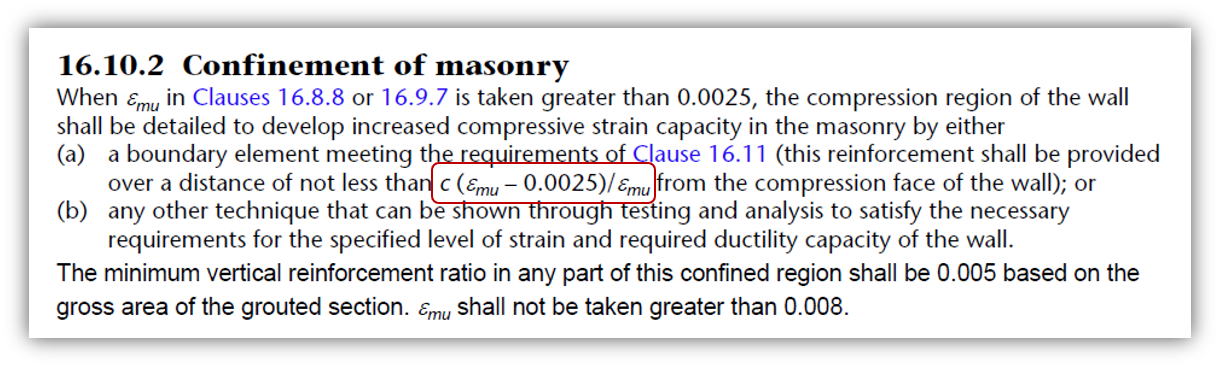
Before jumping in to re-analyzing the shear wall using a higher compressive strain, it’s possible that other aspects of the shear wall may prevent a successful result for other reasons. For instance, in increased compressive strain of 0.009 may be the value needed to bring the inelastic rotational capacity up to meeting demand and satisfying ductility requirements. The problem with that value is that there is a capped maximum strain of 0.008 in CSA S304-14: 16.10.2.
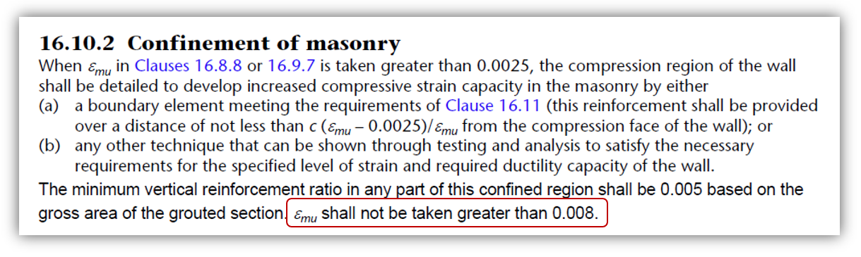 As a result, in this example, it would not be possible to increase the compressive strain to the value needed and to satisfy the ductility verification. As a result, the design fails.
Compressive Strain within Web
Another restriction of how much compressive strain can be increased is section geometry and specifically, how far away the shear wall web is from the compression edge. It is not permitted for strains along the cross section to exceed the default seismic 0.0025 outside of the boundary element.
For this reason, it may not be possible to increase strain to that calculated value that would raise capacity enough to satisfy ductility.
Strain as a Function of Ties
Max allowable strain increase can also be governed by ties (including seismic cross ties). This is calculated and checked automatically by MASS and is another factor in determining whether the strain can be increased to address a failed ductility verification.
It is a combination of all three of these factors that are used by MASS before determining whether or not it is possible to satisfy the verification.
Effect on Neutral Axis
One snag in the process of trying to satisfy the ductility verification is the potential shift in neutral axis location. Choosing a strain that will increase the inelastic rotational capacity to satisfy the ductility verification may also affect the neutral axis location, another variable in the ductility capacity formula.
The process of increasing maximum compressive strain is that when the section is re-analyzed, the strains experienced at each reinforcing bar location will also be altered and as a result, the compression zone calculated by MASS will change to adjust. This relationship is not straightforward and how the neutral axis location changes will depend on a number of factors.
For the same shear wall element cross section, the moment envelope curve as a function of changing compressive strains will look like this: (see below).
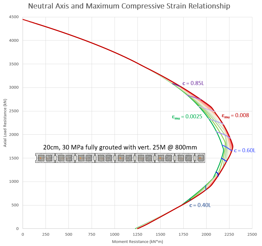
Note: Boundary elements with adequately tied compression reinforcement are needed to increase compressive strain. This example is solely intended to illustrate the relationship between compressive strain and neutral axis location.
As the maximum strain increases, the envelope curve either stays the same or shifts outward from the origin. Marking contours for various neutral axis locations, the direction of movement changes depending on axial load. For designs with low axial loads, the neutral axis contours move down and to the left as moment resistance and axial load capacity is reduced as a result of higher strains experienced by bars on the same side of the cross section as the masonry compression block counteracting the compression forces. As the axial load increases and the compression zone moved toward the horizontal center of the wall, the steel forces affected by the changing strain profile increase the walls capacity and the neutral axis contours move outward from the origin. Once the axial load is high enough such that steel is no longer in tension, there are no changes to the PM diagram load envelope curve as changes in strains have no impact on internal forces experiences within the cross section.
Overall Strategy Summary
When a multi-storey shear wall is designed using MASS, the goal of the software is such that the end result meets the following two sets of conditions:
Capacity Design: All design criteria from each individual element is satisfied (shear wall has adequate capacity and satisfied all clauses checked by the software). This is referred to within the design strategy article as the Capacity Design stage (click here to jump back up to that section).
Group Equalization – : Shear wall element designs part of the same Group are designed with the same cross sectional properties, sharing the same masonry unit, grouting pattern, and reinforcement configuration between grouped storeys. This is referred to as the Group Equalization stage. (click here to jump back up to that section).
Additional requirements are optional and applied as required based on geometry, loading, and seismic inputs:
Structural Irregularities (optional): Shear walls are checked for structural irregularities only for designs where an earthquake type load is applied and the Equivalent Static Force Procedure has been selected in the Seismic tab. This is referred to within the design strategy article as the Structural Irregularities stage (click here to jump back up to that section).
Drift (optional): Shear walls are designed to not deflect beyond the inter-storey drift limits under load combinations containing an earthquake type load. this is referred to as the Drift stage. (click here to jump back up to that section).
Ductility (optional): Shear wall designs containing a plastic hinge region are required by the CSA Standards to satisfy ductility requirements. This is referred to as the Ductility stage (click here to jump back up to that section).
These stages are laid out in the simplified flowchart, pictured below:
Successful Multi-Storey shear wall results indicate to the user that MASS has checked and designed based on these requirements as they are applicable.
Continue Reading: Multi-Storey Load Distribution