

Latest Software Blog Posts
Understanding the Minimum Boundary Element Length Limits on Strain
While not explicitly listed as a strain limit, the minimum boundary element size can have a large effect on how high maximum compressive strain can be increased.
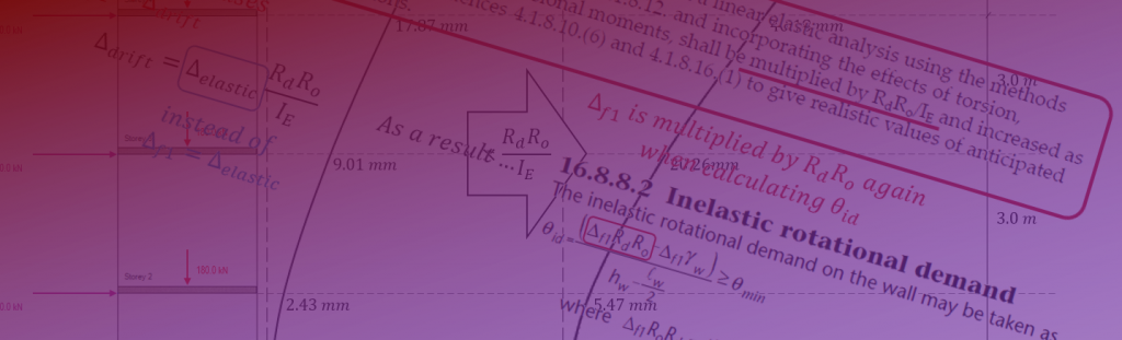
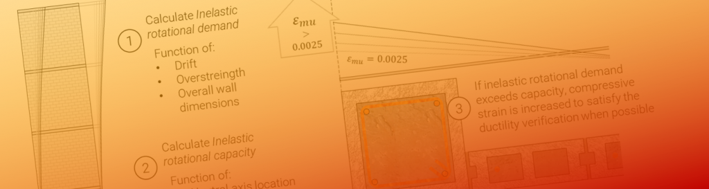
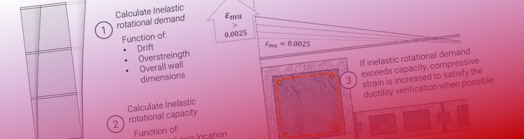
As part of the process of addressing a shear wall design with inadequate ductility, MASS will increase the maximum compressive strain, εmu in an effort to bring the inelastic rotation capacity, θic, up to meeting the inelastic rotational demand, θid.
Explained as part of the design strategy article linked here, the software will first determine the value of εmu that would in theory satisfy ductility before comparing it against other design constraints. This post will primarily focus on how shear wall geometry and in particular, boundary element length, can affect the upper limits on how much εmu can be increased.
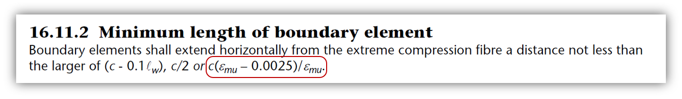
CSA S304-14: 16.10.2 specifies a minimum boundary element length, shown in sentence a) below:
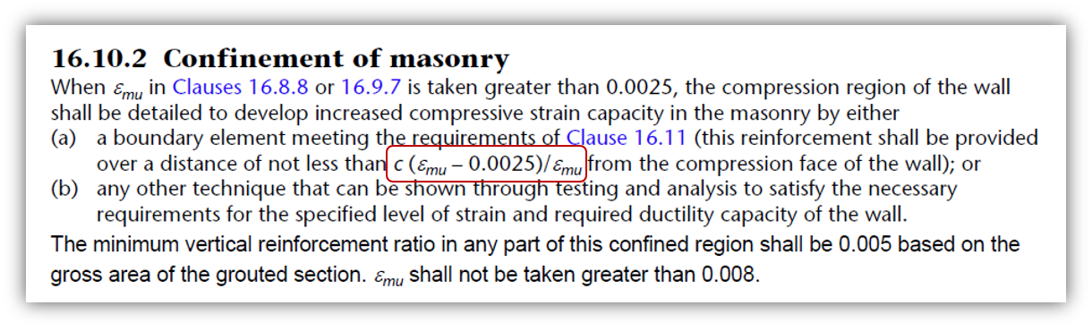
This minimum length is specified to ensure that the compressive strain occurring along the cross section outside the boundary element does not exceed the magnitude that would be acceptable for designs not containing elements that are capable of confining masonry in compression.
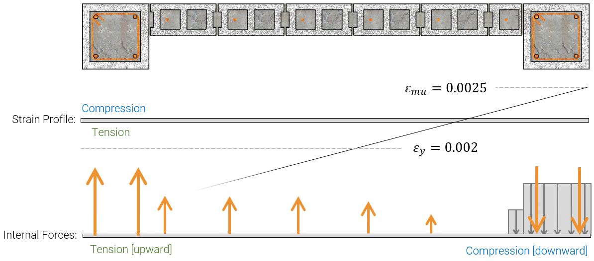
Looking at a shear wall cross section, under the plane sections remain plane assumption, the largest compressive strain will occur at the edge of the wall in compression. Groundbreaking stuff, I know! There are no potential issues with higher strains anywhere else within the wall for this reason. Note that the purpose of this basic review is to highlight how things are change when that extreme compressive strain, εmu, is increased.
The figure below shows a shear wall loaded from left-to-right (default direction in MASS) where the strain profile and internal cross sectional forces are shown:
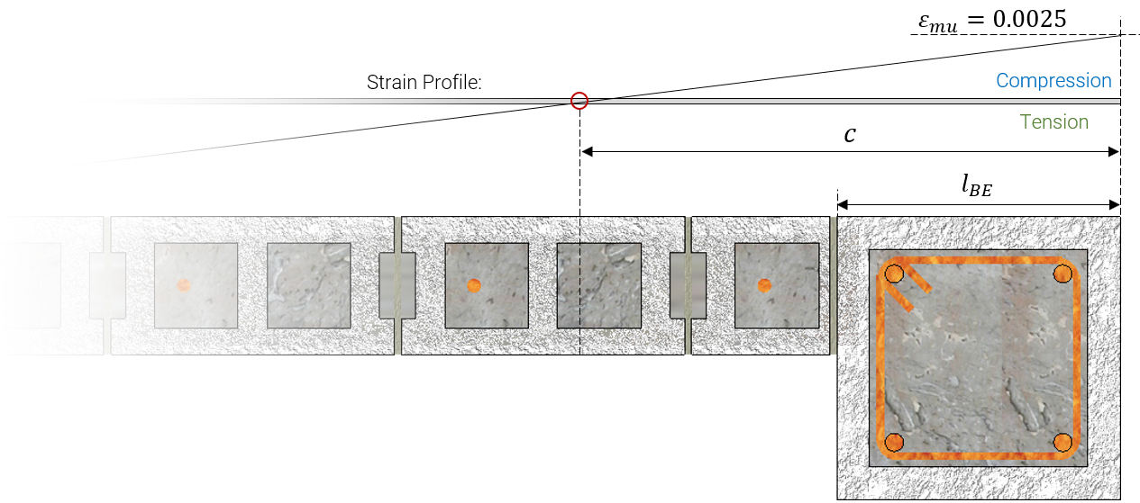
Zooming into the compression area with the strain profile, the boundary element length and neutral axis depth are labelled below:
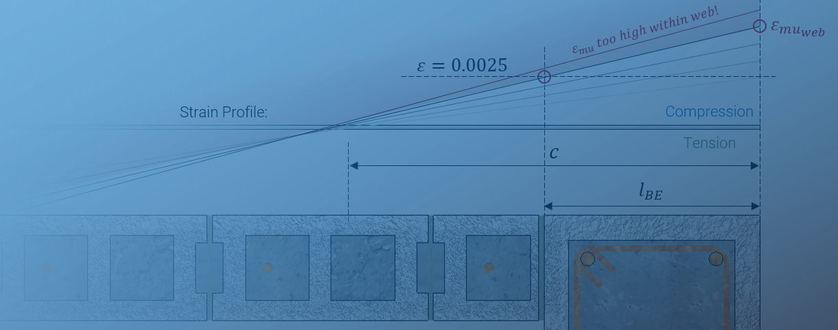
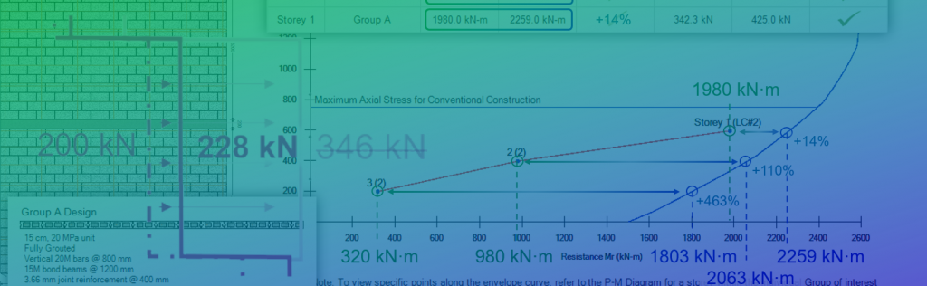
Boundary elements that are designed and detailed using the added provisions of CSA S304-16, 10 and 16.11 open up the option of higher compressive strains within those regions. The absolute maximum value that can be used goes all the way up to 0.008 but the compressive strain within the web can end up governing in many cases. In particular, this tends to come up in designs with larger compression zones which is a function of applied axial loading.
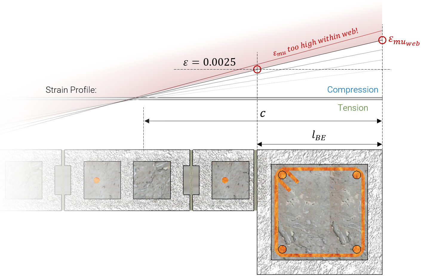
There is a point where the increased εmu used at the compression edge of the wall causes a strain within the web reaching it’s limit. This is referred to with MASS as εmu,web as it is a maximum compressive strain governed by reaching 0.0025 within the web.
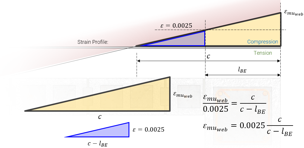
The magnitude of εmu,web is one of a few factors that may influence the increase in compressive strain used when performing a ductility verification. The expression used by MASS to determine εmu,web is derived using similar triangles, shown below:
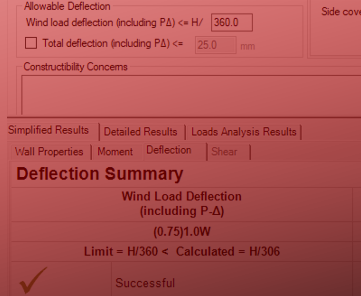
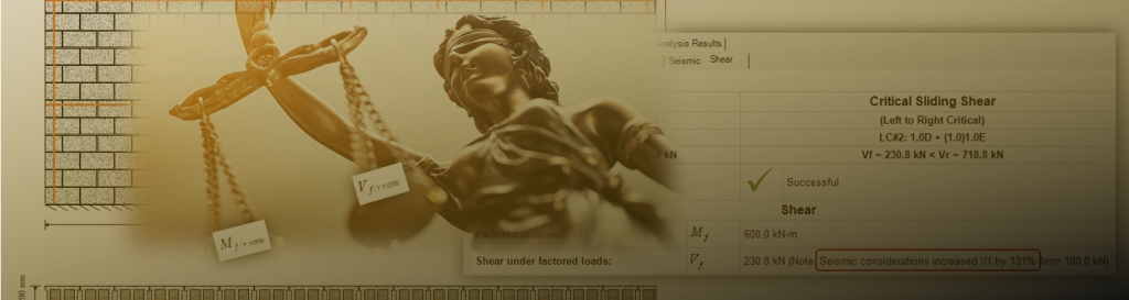
The result can be seen below in MASS under the Detailed Seismic results tab:
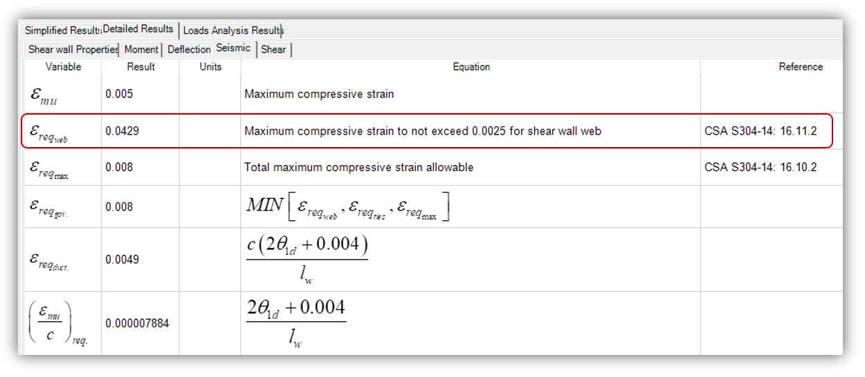
In this example, the calculated value is so large that it does not even come close to governing the largest compression strain possible.
If you’re still reading, here is some bonus content for you! The minimum boundary element expression can also be derived using different similar triangles from the same strain profile figure used above.
Based on a set maximum compressive strain, the smallest length possible for the boundary element in compression is derived below:
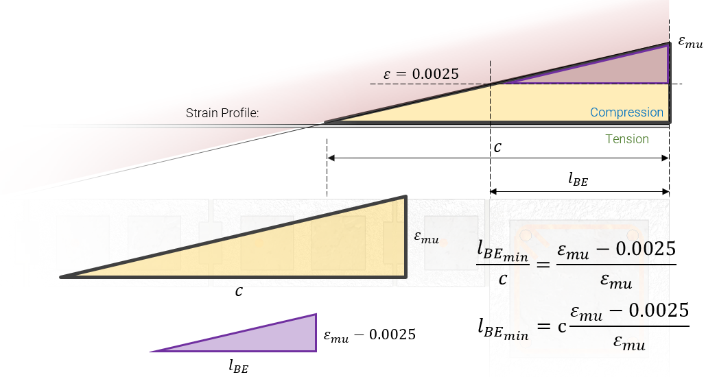
Look familiar? This is the limit shown earlier in clause 16.10.2, which also appears in the boundary element subsection within Chapter 16:
To wrap things up, compression strain occurring within a shear wall web can be the limiting factor in whether it’s even possible to satisfy the ductility verification. The issues and concerns vary so much from project to project so if you have any questions, please do not hesitate to call or email MASS support. After all, it’s included in your MASS software license at no extra charge so feel free to get more than your money’s worth!


Thanks for reading! If you feel like your intelligence was insulted in my breaking down the similar triangles and how the formula derivation in the CSA Standards relates to the strain profile, leave a comment below!