Latest Software Blog Posts
Why ISN’T the Factored Shear Force Scaled up for a Seismic Design?
While you might not have expected it, MASS has it’s reasons for leaving your factored shear alone – even with earthquake loads applied
As covered in a series of posts available here, it is common for designs to be greatly affected by the additional considerations for seismic design. All shear wall designs with an earthquake type load combination are likely to see one or both of factored shear and shear resistances impacted by these considerations. This post outlines the one exception where these changed need not be applied.
Disclaimer: This post is exclusively intended to provide insight into the approach taken by the MASS design software in interpreting a CSA S304-14 code compliant seismic design. It is up to the professional discretion of the designer to input an appropriate layout, boundary and loading conditions, interpret the results, and determine how they should be incorporated into their designs. As per the end user license agreement (and also recommended within PEO’s guidelines for using engineering software), a tool cannot be considered competent and reliance on a tool does not relieve the user of responsibility.
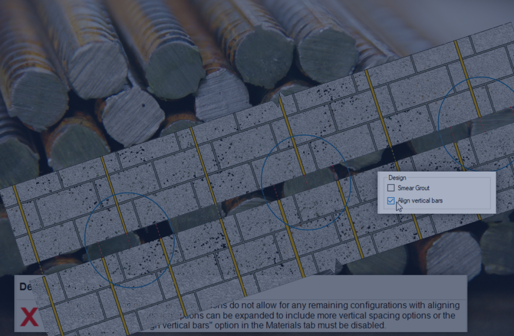
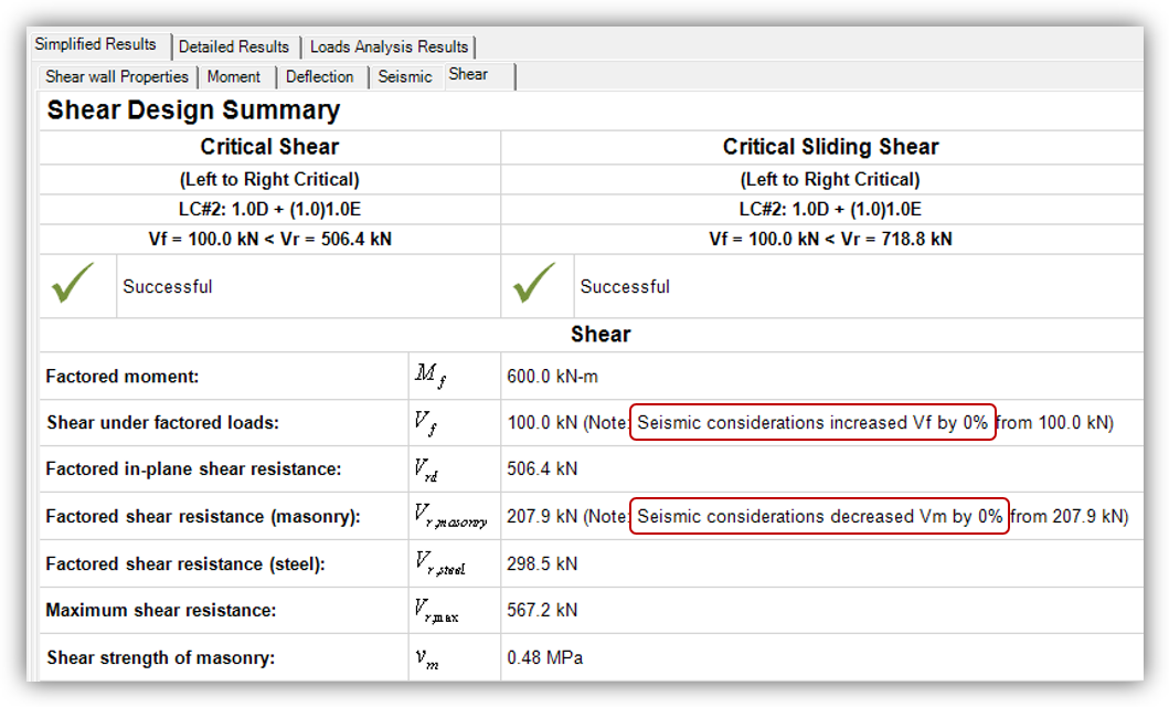
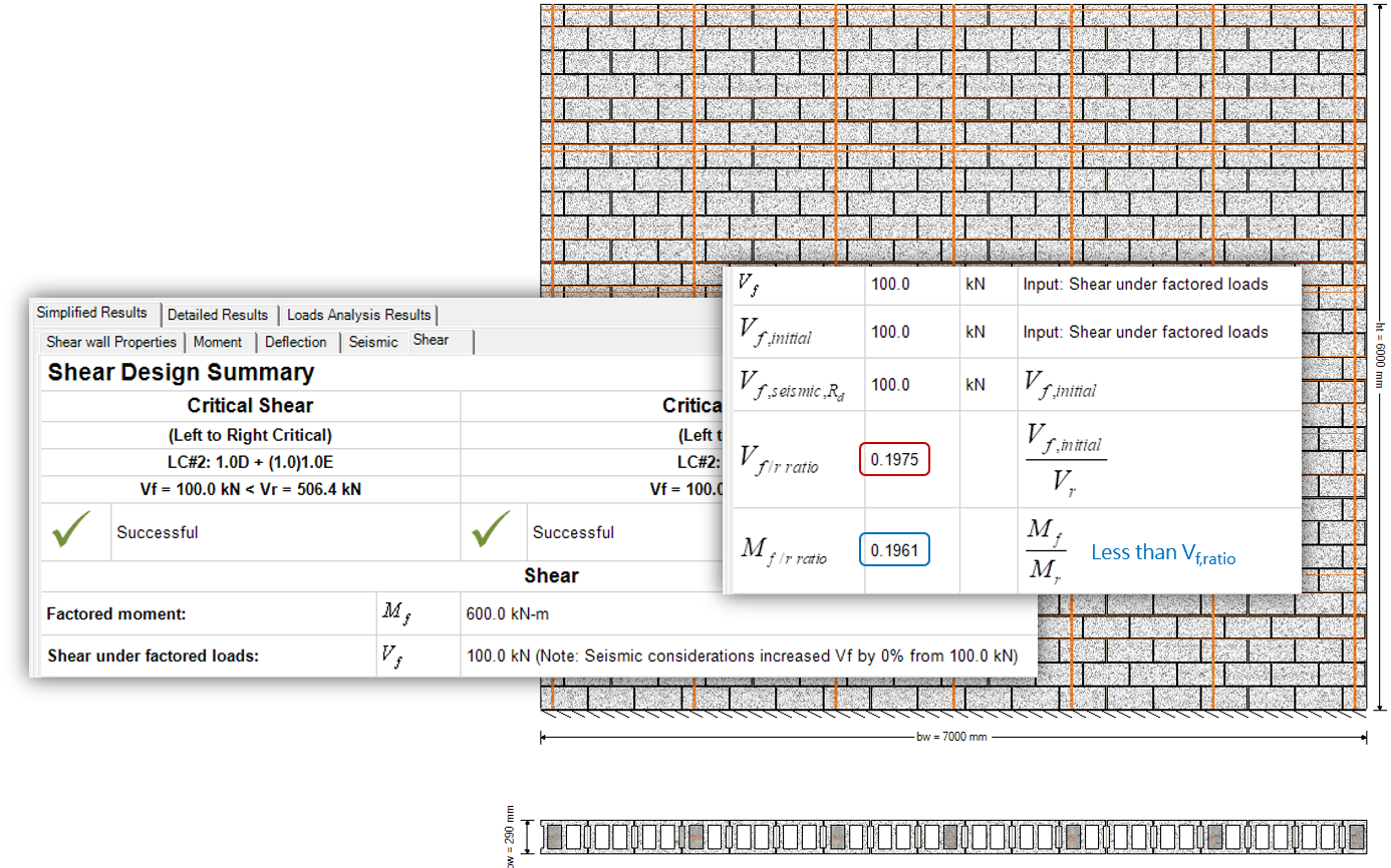
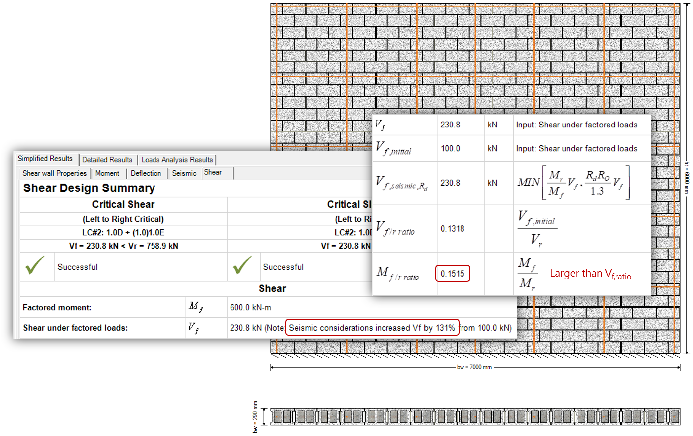
This post outlines why shear design results like the following might occur:
There are two cases where a design does not have any amplification to the factored shear for a masonry shear wall:
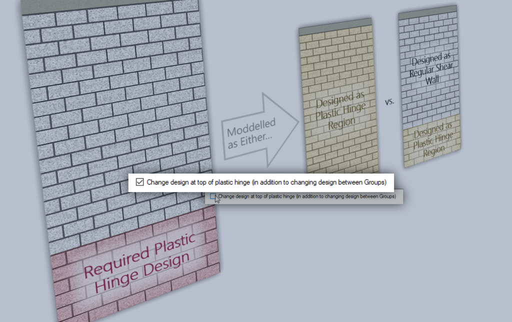
Conventional Construction Shear Walls
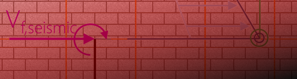
The moment resistance is exactly equal to the factored moment, resulting in a perfect one to one scaling of Vf,seismic to Vf,initial (only applicable for conventional construction as nominal or probable moments will always be higher for increased ductility).
Moderately Ductile Squat Shear Walls
By using CSA S304-14: 16.7.3.2 Note (2), the software identifies a shear failure mechanism (as opposed to a flexural failure mechanism). This is the design scenario explained here.
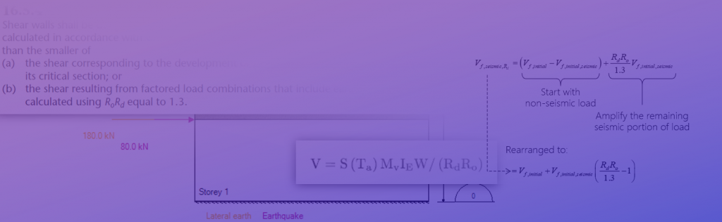
For reference, the relevant requirement from CSA S304-14 in Clause 16.7.3.2 is shown below:
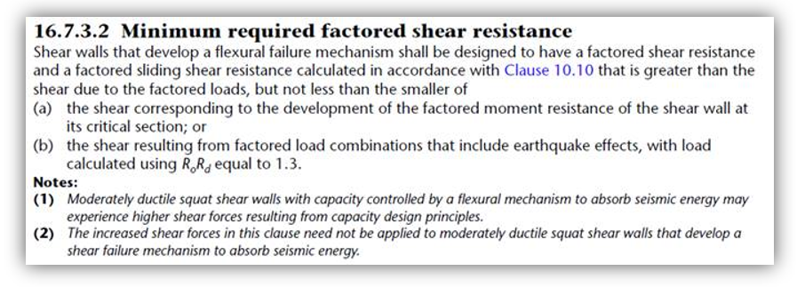
Parts (a) and (b) are explained in further detail here, with a shear wall element and multi-storey application and examples linked.
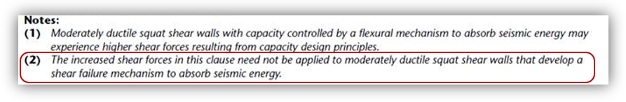
(2) The increased shear forces in this clause need not be applied to moderately ductile squat shear walls that develop a shear failure mechanism to absorb seismic energy
The notion of “needing not apply” the rest of this clause can be an attractive one in the midst of banging your head against your desk, trying to get a design to be successful for both moment and shear. As seen in Note (2), being able to apply the provisions of Note 2 depends entirely on the identification of a shear failure mechanism.
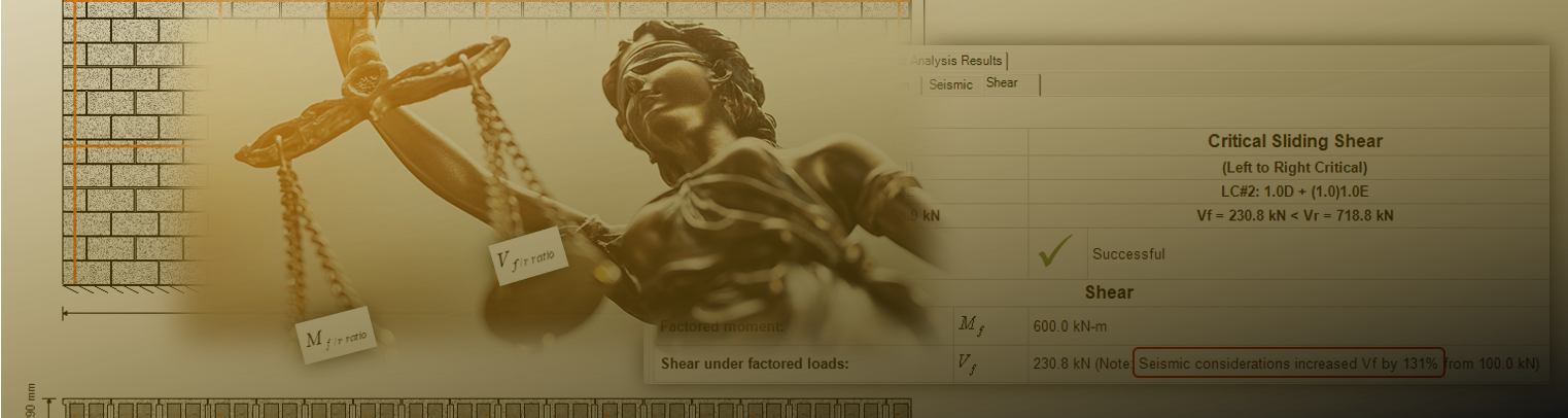
What are ratios and what do they mean?
Within the detailed shear results, you may have noticed an Mf,ratio and a Vf,ratio listed among the equations and references. The distinction between a shear failure mechanism as opposed to a flexural failure mechanism is based on how close a shear wall’s factored loading brings it to the corresponding resistance the relative terms.
A shear failure mechanism is assumed by the software to exist when Vf,ratio exceeds Mf,ratio. In these cases, it is determined that as a result, the rest of CSA S304-14: 16.7.3.2 need not be applied and factored in-plane shear does not experience any amplification.
See the example design below:
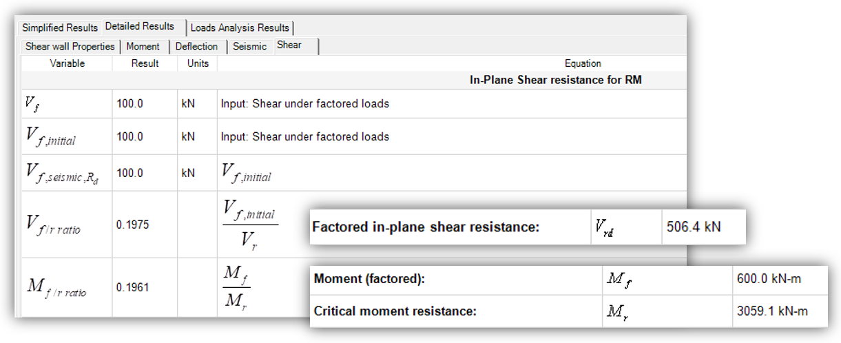
While very close in this case, the shear wall is technically considered to have a shear failure mechanism. As a result, there is no need to amplify the factored shear force.
Contrast this same design with a fully grouted wall with the same dimensions, masonry unit, and reinforcement configuration. The presence of the grout helps with both the flexural and shear performance but the effect is greater on shear resistance. As a result, the failure mechanism identified is flipped form shear to moment, seen below:
Since the factored shear ratio is now reduced further than the factored moment ratio reduction, the failure mechanism is flexural and the remainder of clause 16.7.3.2 must be applied.
Concluding Thoughts
Decisions made during moment design can have intended consequences further along during shear design. While the other seismic considerations can punish any additional flexural over-design, the specific case of moderately ductile squat shear walls can be particularly devastating.
One more thing to note is that for this example, the applied in-plane earthquake load was quite large for a single storey structure, at an unfactored (and factored) 100kN. That being said, the results ended up being independent of loading. “Why?” – you may ask audibly to your computer to no avail. As it turns out, the masonry unit size was a function of the required thickness in order to satisfy the unsupported height requirements of CSA S304-14: 16.7.4:
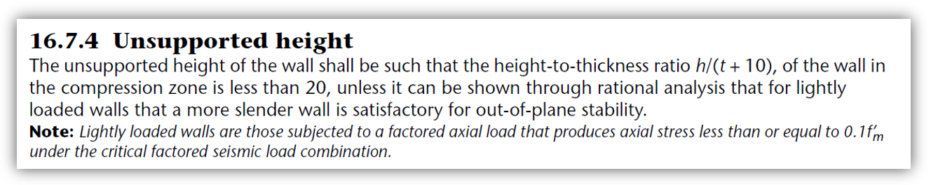
This example just barely satisfies this height limit with 6000 mm / (290 mm + 10 mm) = 20.
Moderately ductile squat shear walls also have punitive reinforcement requirements implemented as ratios, outlined in CSA S304-14: 16.7.5:
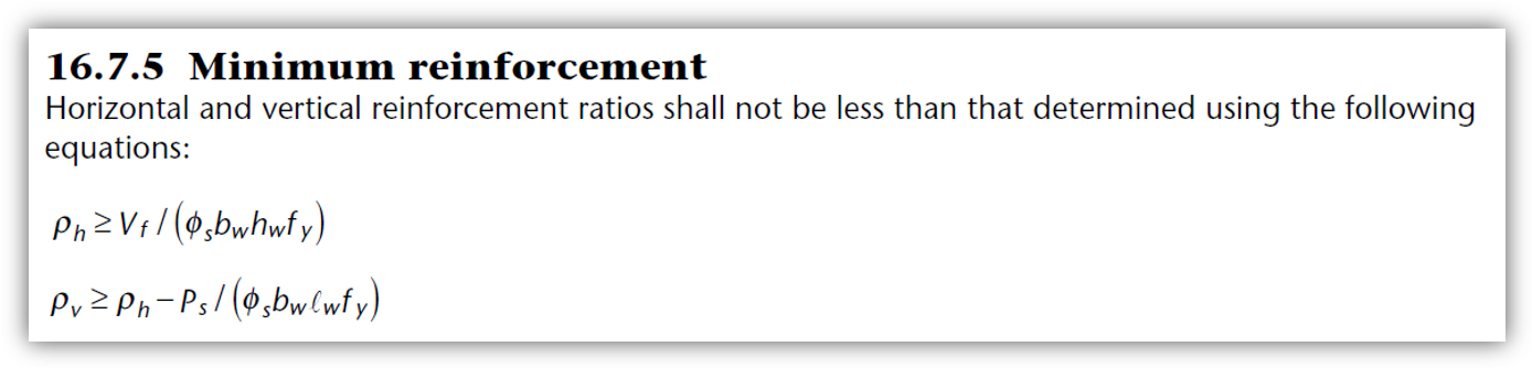
Due to the large unit, the vertical and horizontal reinforcement in the final design was placed largely in order to satisfy these requirements.
If you are encountering issues designing a moderately ductile squat shear wall, re-examining your moment design may be worth exploring. If you are still looking for answers, please do not hesitate to contact MASS support.