

Design Steps
Contents
This section provides a brief overview of the steps necessary to complete a design, as well as the type of useful information that can be retrieved about a successful or unsuccessful design. With the help of this section, a user is able to successfully complete a design, even with only a minimal amount of knowledge in masonry design. For detailed instructions on using the beam, out-of-plane wall, shear wall, multi-storey shear wall or shearline design modules, refer to their respective pages.
There are four design steps common to all three modules:
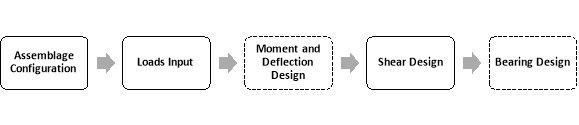
Figure 2-3: MASS™ Design Steps
The deflection design is available for the beam and out-of-plane module only. The bearing design step is available for the beam module only.
Assemblage configuration is the first design step; it allows users to enter the material properties of the assemblage. Loads input is the second design step; it allows users to apply multiple load distributions (point load, line load, triangular load, trapezoidal, and moment), as well as multiple types of loads (dead, live, snow, wind, earthquake, storage, controlled fluid, soil, and contraction/expansion). Using these loads, the program determines the corresponding load combinations. Moment and deflection design is the third design step; at this stage, the program designs the assemblage such that the moment resistance of the assemblage exceeds the critical factored moment determined at the loads input stage. Shear design is the forth design step; at this stage, the program designs the assemblage such that the shear resistance exceeds the shear due to the applied factored loading. The beam module has an additional design step: bearing design. At this stage, the bearing detailing is performed.
The toolbar at the top of the screen is used to step through all five design steps. This is shown in Figure 2‑4.
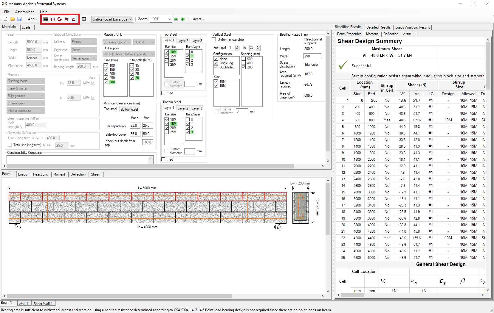 Figure 2‑4: Toolbar (Design Steps)
*Note: The status bar at the bottom of the page indicates to users what to do next
Assemblage Configuration
Assemblage configuration is the first step in developing a design. This step allows users to enter the material properties of the assemblage.
- Enter the assemblage dimensions (length, height, and width in mm)
- Select the type of masonry unit (concrete or brick, hollow or semi-solid), and the size and strength of the unit.
- Choose the appropriate support conditions
Enter the assemblage dimensions
In the case of a beam, two dimensions must be entered: the length and the height. All dimensions in the program are entered in millimetres. A beam with a length of 3000 mm, and a height of 590 mm has been specified in Figure 2‑5. As soon as the assemblage dimensions are entered, the assemblage drawing is available. Notice that when performing the assemblage configuration design step, the Assemblage Configuration button is outlined in blue.
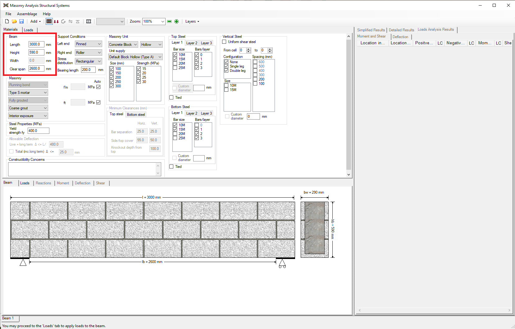
Figure 2‑5: Entering Dimensions of an Assemblage
*Note: The program recognizes either a modular dimension or a modular minus 10 mm, or anything in between, as being composed of full and not cut blocks, and uses the smaller value in design calculations. Dimensions that are non-modular require units to be cut on-site. This may increase construction cost.
At this stage, it would be possible to proceed to the loads input design step. This is because the program provides default selections for the support conditions, the masonry unit properties, and the masonry properties. However, because users are typically interested in altering the support conditions and the masonry unit properties for each design, this is explored further in this section.
Choose the Type of Masonry Unit
There are five masonry unit properties that can be altered at this stage. The first is the type of unit a designer wishes to select: concrete block or clay brick (beam module only). Users can also select the solidity of the unit (whether it is hollow, semi-solid, or solid). The default unit types are shown in Figure 2‑6.
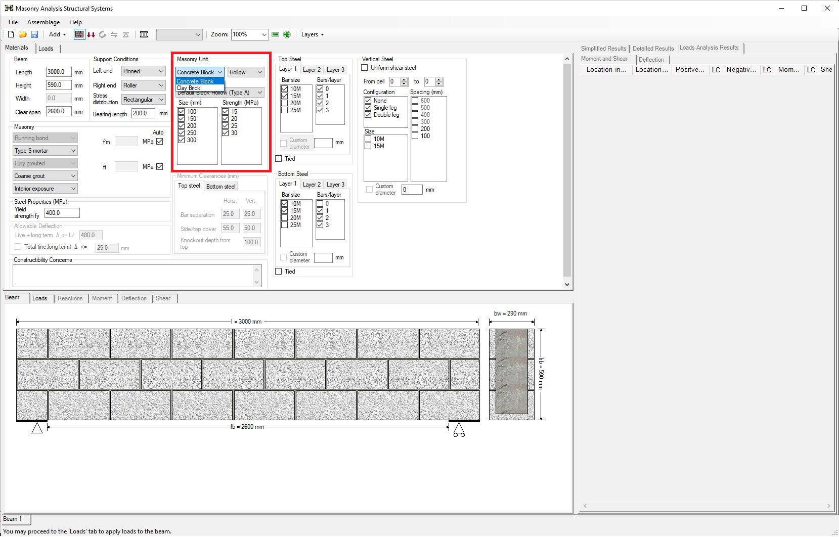
Figure 2‑6: Choosing the Type of Masonry Unit
Users can specify the supplier of the masonry unit. This is typically altered from the defaulted value when creating a personalized unit.
*Note: In addition to the available block types, users are also able to create a new unit with customized properties) using the Masonry Unit Database.
It is possible to select the specific size and strength of the unit, by checking-off all other unit sizes and strengths. In the program, the size of the concrete block refers to the nominal thickness, t+10 mm, of the masonry unit. The size of a brick refers to the actual thickness. A hollow 20 cm (200 mm) concrete block unit with a strength of 25 MPa is selected in Figure 2‑7.

Figure 2‑7: Choosing the Size and Strength of the Masonry Unit
By default, the program leaves all possible sizes and strengths checked-on. It iterates through these possible values, beginning with the smallest and weakest block, and selects the first of these that meets the engineering requirements.
Support Conditions/End Fixity
Support conditions should be specified prior to the application of any loads. For beams, the possible support conditions are fixed, pinned, roller, and free. In this version of the program, the beam is only permitted to be cantilevered on the right side, the left side is fixed. A beam with pinned-roller support conditions is shown in the top window of Figure 2‑8. The support conditions chosen are reflected in the beam drawing in the bottom window of Figure 2‑8.
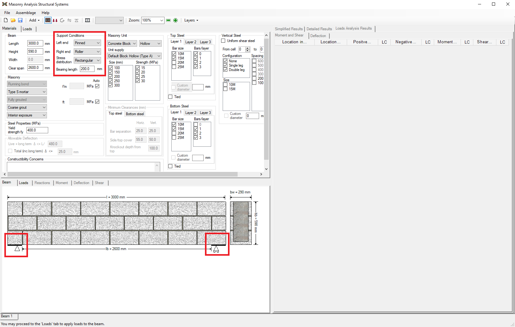
Figure 2‑8: Choosing the Support Conditions
The stress distribution (under concentrated loads) at the supports must also be specified. The default stress distribution is triangular.
*Note: CSA S304-14: 7.14.1.1 indicates that the stress distribution for bearing design is assumed to be triangular, unless the bearing length is 300 mm or greater, in which case it is assumed to be uniform.
As can be seen in Figure 2‑9, users can specify additional masonry properties (such as the mortar type or the compressive strength). These properties are explored in more detail in the respective sections for each module, beam, out-of-plane wall, shear wall, multi-storey shear wall or shearline design modules. At this time, users can proceed to the loads input design step.
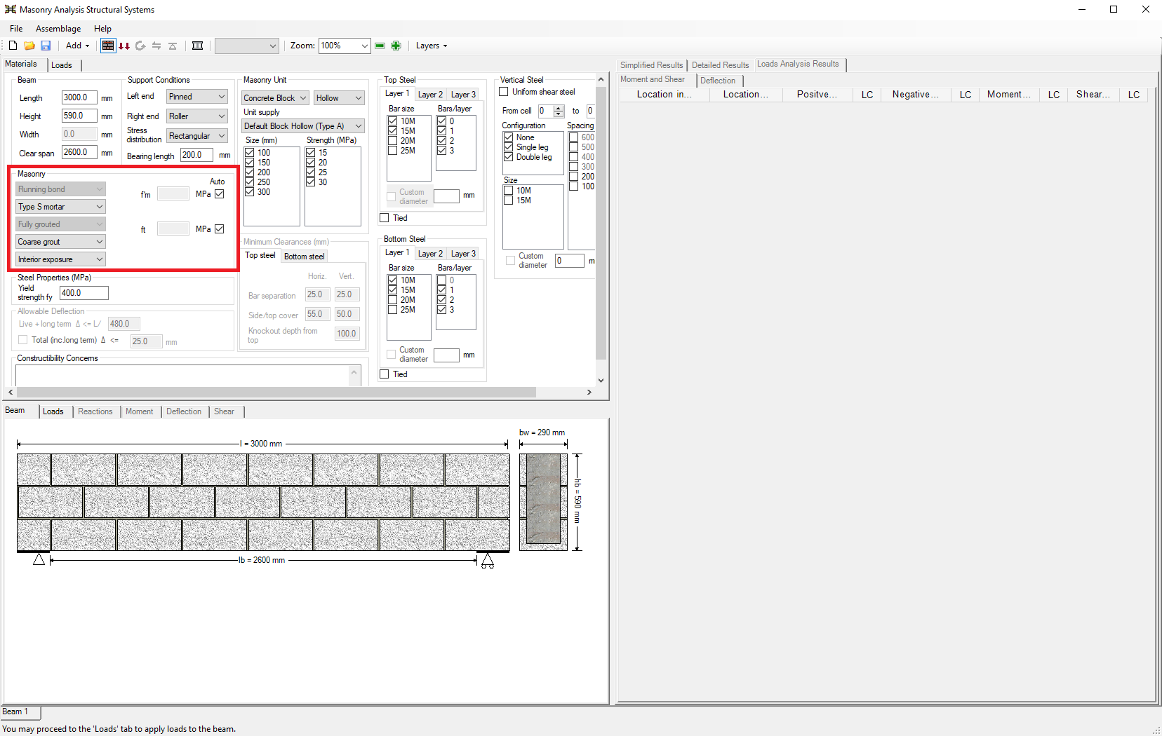
Figure 2‑9: Choosing the Masonry Properties
Loads Input
Loads input is the second step in developing an assemblage design. This step allows users to enter the loads that are applied to the assemblage. Loads are applied in the same manner for all assemblage types:
- Click on the Loads Input button
 , or on the Loads tab
 - Choose the importance category (low, normal, high, post-disaster)
- Click on Add Load
- Enter in load properties (load type, distribution, location, unfactored magnitude, units, and percentage of load sustained)
Loads Input
There are two ways to begin the loads input design step: click on the Loads Input button or the Loads tab. Notice that when performing the loads input design step, the Loads Input button is outlined in blue, as shown in Figure 2‑10. Upon moving into the load inputs design step, the program automatically displays to the assemblage drawing in the Loads tab in the bottom window.
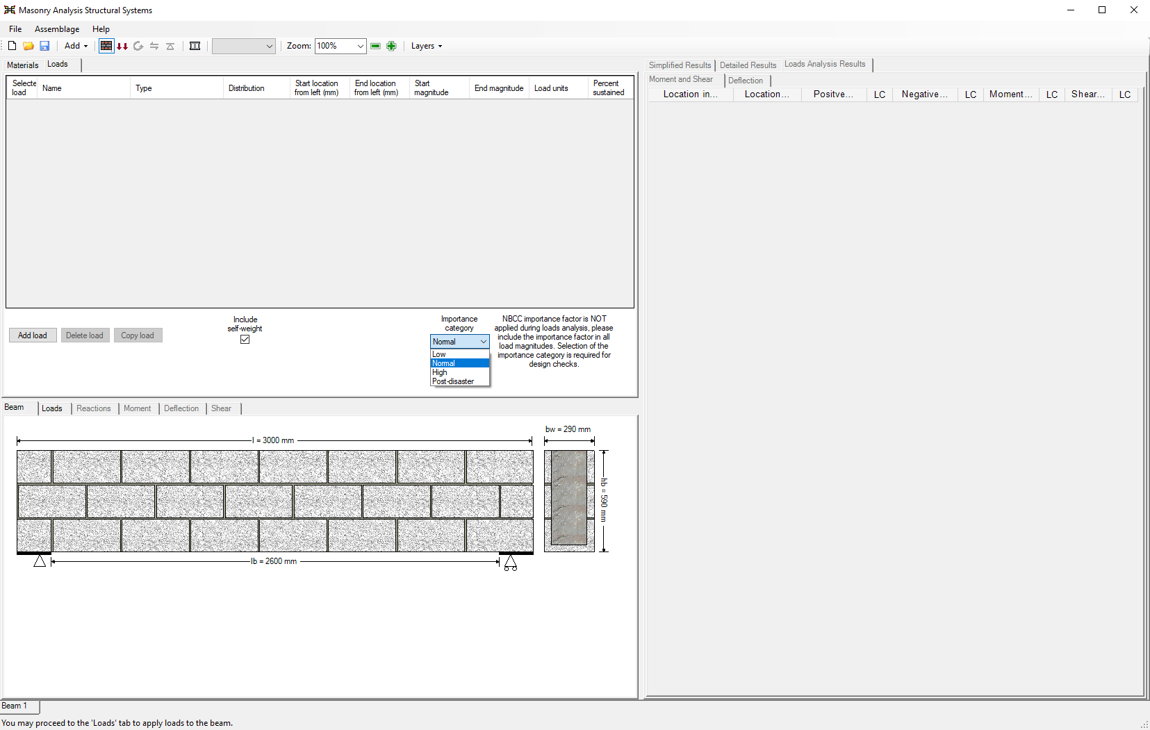
Figure 2‑10: Loads Input Design Step
Importance Category
The importance category specifies the importance of a building, determined based on the hazard a building failure could pose. Depending on the importance category chosen, MASS will conduct the necessary design checks. The importance category is selected using the drop-down box under the heading ‘Importance category’, shown above in Figure 2‑10. The possible importance categories include: low, normal, high, and post-disaster. The default importance category is ‘Normal’.
*Note: The NBCC importance factor is NOT applied during load analysis, please include the importance factor in all load magnitudes. Selection of the importance category is required for design checks.
Load Properties
To add a load, click on the Add Load button. For beams, the program allows for the selection of the following loads: dead, live, snow, wind, earthquake, storage, controlled fluid, soil, and contraction/expansion. These can be selected using the drop-down box found under the ‘Type’ column, shown in Figure 2-11.
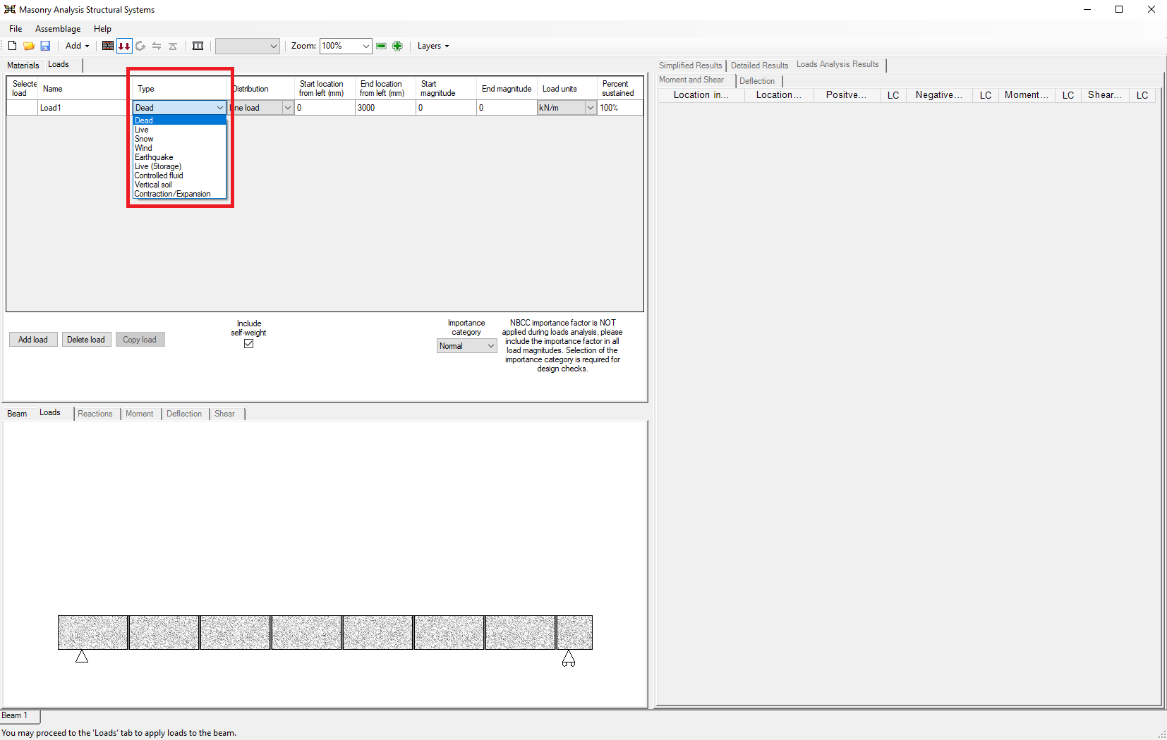
Figure 2‑11: Choosing a Load Type and Load Distribution
Similarly to choosing a load type, users can choose the load distribution using the drop-down box found under the ‘Distribution’ column. The load distribution opportunities are extensive. Load distributions that can be applied to an assemblage include point loads, line loads (uniformly distributed, triangular, and trapezoidal), and moments. The possible distributions permitted depend on the assemblage.
The program allows users to enter a start and end location for both the location of the load, and the unfactored magnitude. This provides large versatility in the type of loads that can be applied. In Figure 2‑12 for instance, a downward triangular load with a start unfactored magnitude of 5 kN and an end unfactored magnitude of 1 kN is applied at the right side of the beam (beginning at 1500 mm and ending at 3000 mm).
*Note: According to MASS™ sign convention, a downward applied load is considered a positive load. A moment applied in the clockwise direction is considered a positive moment.
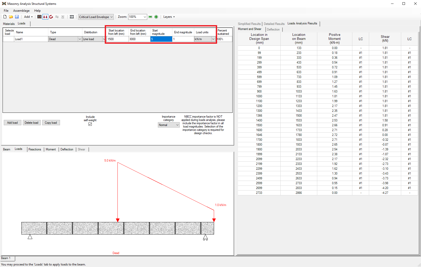
Figure 2‑12: Entering Load Properties
The units of the load can be specified using one of the following units (kN/m, N/m, lb/ft, or kip/ft) simply by selecting the drop-down box under the ‘Load units’ column. The percentage of the load being sustained can be entered in the ‘Percentage sustained’ column.
To the left of the ‘Importance category’ drop-down box is the ‘Include self-weight’ check-box. The self-weight is included in the load calculations by default; however, users can choose to exclude the self-weight of the assemblage by checking-off the ‘Include self-weight’ check-box.
To add additional loads, click on Add Load. Note, that loads can be deleted using the Delete Load button and copied using the Copy Load button. With each new load added, the program uses the ‘Load Type’ selected in order determine the corresponding factored load combinations (governed by CSA S304-14: 4.2.2). To view all applicable load combinations click on the Critical Load Envelope drop-down box, as shown in Figure 2‑13.
A specific load can be viewed under the Loads tab by clicking on the box of a particular load (under the ‘Selected Load’ column). Multiple loads can be viewed by holding down Shift key, and selecting the loads one wishes to display. Figure 2‑13 shows two selected loads that are displayed in the loads drawing (under the Loads tab). The applied loads that are being displayed are highlighted in blue.
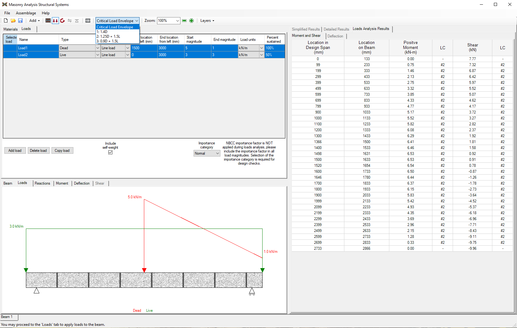
Figure 2‑13: Multiple Loads
Upon the completion of the loads input design step, users can proceed to the moment and deflection design step.
Moment and Deflection Design
Moment and Deflection Design is the third step in developing an assemblage design. In order run the moment and deflection design:
- Click on the Moment and Deflection Design button
 , shown in Figure 2‑14
This completes the moment and deflection design step. The ‘Moment Design Summary’ page, as well as the status bar at the bottom of the page provides information on whether or not a successful design is found. Highlighted in green are the masonry unit properties and the steel properties that provide a successful design, as can be seen in Figure 2‑14. Notice, also, that the design selections are reflected in the assemblage drawing.
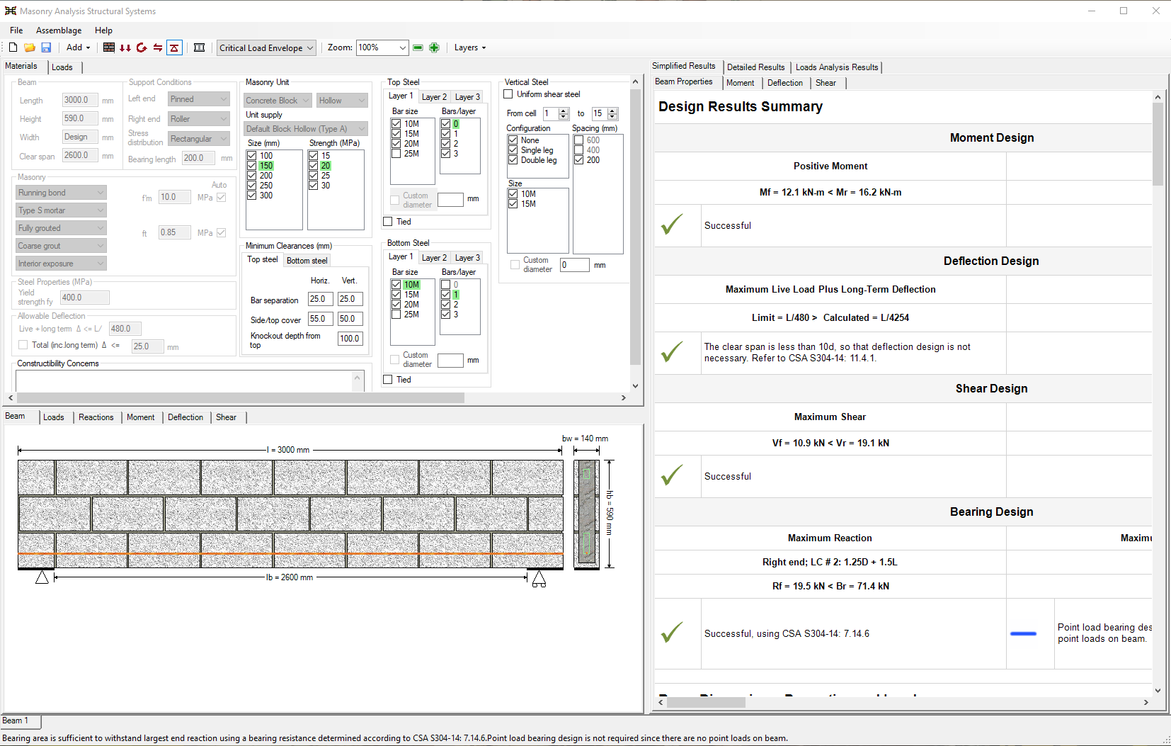
Figure 2‑14: Moment and Deflection Design (Successful)
Unsuccessful Design
An unsuccessful moment and deflection design still provides users with all appropriate outputs, and the program clearly indicates the design has failed, as shown in Figure 2‑15.
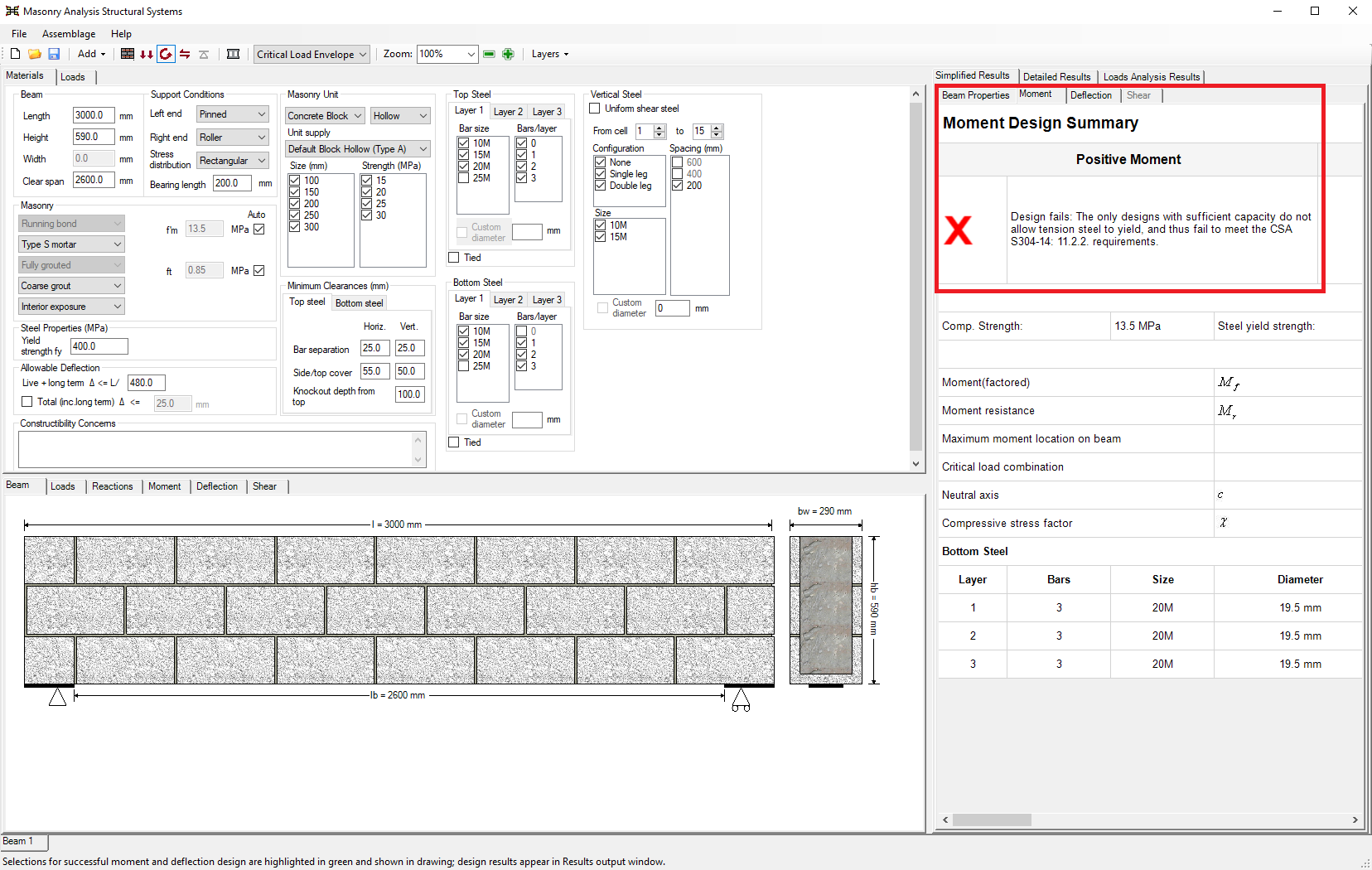
Figure 2‑15: Moment and Deflection Design (Unsuccessful)
Upon the completion of a successful or unsuccessful moment and deflection design, users may wish to alter the design provided by the program. Under the Materials tab, it is possible to change any of the material properties previously entered or selected. Users can now also change the steel properties used within the design by selecting only the desired number of bars and bar sizes. The program automatically re-triggers the moment and deflection design step if any of the check-box material selections are altered. For new values that are entered into a textbox (for instance, the length of a beam) press Enter on the keyboard to re-trigger a design. For more details, refer to the beam, out-of-plane wall, shear wall, multi-storey shear wall or shearline design modules pages.
Shear Design
Shear design is the fourth step in developing a design. To run the shear design:
- Click on the Shear Design button
 as shown in Figure 2‑16.
This performs the shear design step. The ‘Shear Design Summary’ page as well as the status bar at the bottom of the page informs users whether or not a successful shear design is found.
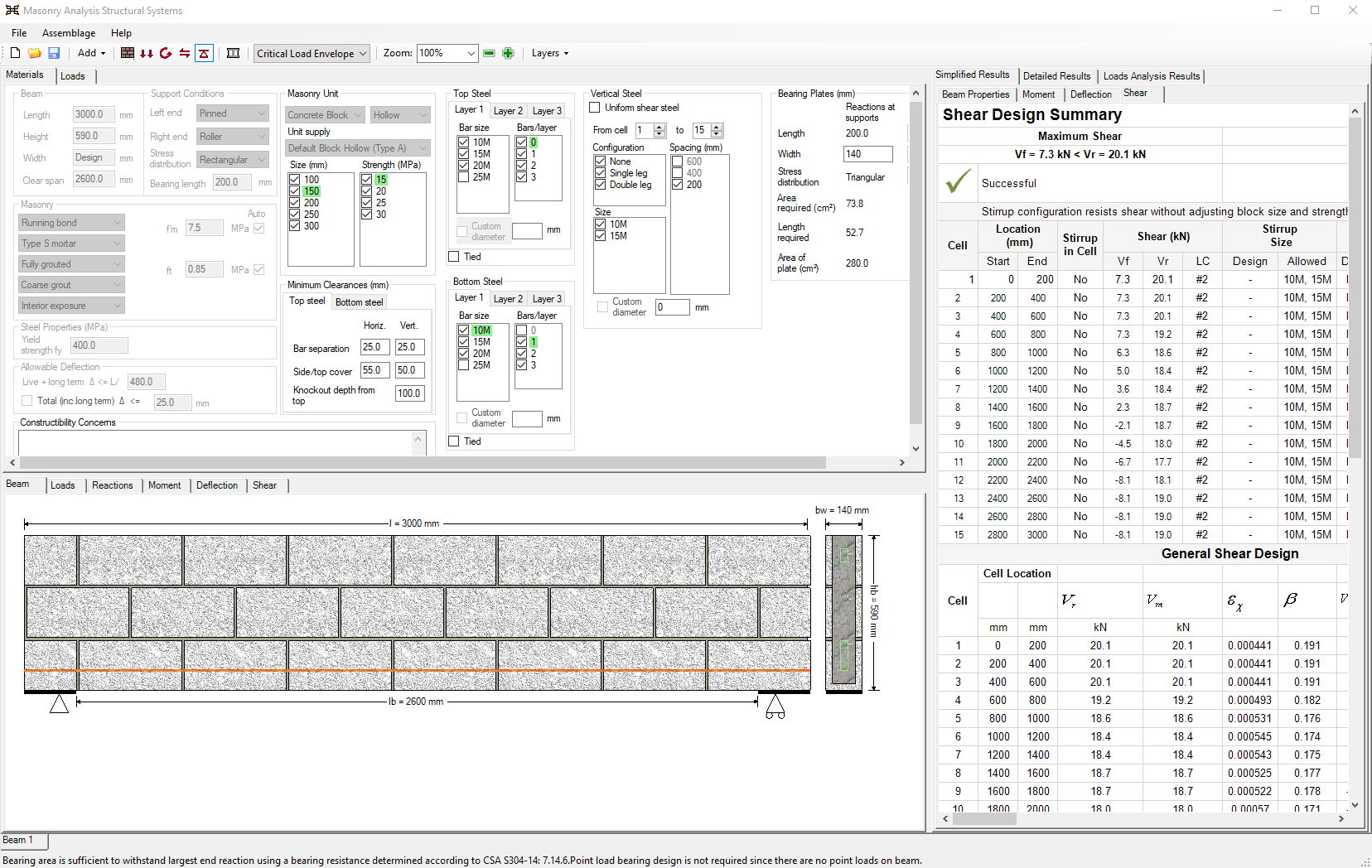
Figure 2‑16: Shear Design (Successful)
The program automatically re-triggers the moment and deflection design step if any of the check-box material selections are altered. For new values that are entered into a textbox (for instance, the length of a beam) press Enter on the keyboard to re-trigger the moment design.
This completes the shear design step. A successful shear design is found as can be seen in the ‘Shear Design Summary’ as well as in the status bar. The vertical steel properties used in the beam assemblage are not highlighted in green because the properties may change along the length of the assemblage. The vertical steel used is however displayed in the beam drawing. For more details, please refer to the sections Beam Design Steps, A Complete Beam Design, and Beam Design Strategy.
For out-of-plane walls and shear walls this signifies a completed design. The designer is responsible for any remaining design obligations (for instance, detailing). In the case of beams however, there is one more design step.
Unsuccessful Design
The beam designed thus far has passed all four design steps. However, if the shear design fails based on user-specified selections, it is possible to return to previous design steps. If a design is unsuccessful in the shear design step:
- Return to the moment and deflection design step by clicking on the Moment and Deflection Design button:
 .
. - Under the Materials tab, change the material properties previously entered or selected. To complete the shear design step by clicking on the Shear Design button: once more.
*Note: An unsuccessful design may be yielded not because the design is unacceptable, but because the program does not handle shear design of deep beams (CSA S304-14: 11.2.7).
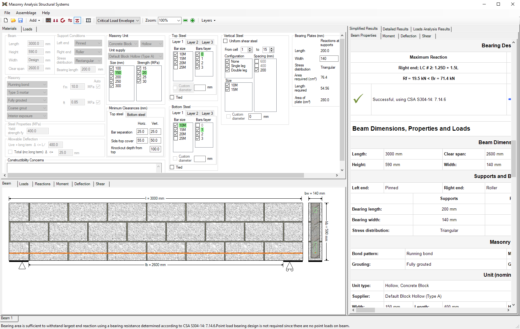
Bearing Design
The beam assemblage has an additional design step: bearing design. To run the bearing design:
- Click on the Bearing Design button
 shown in Figure 2‑17.
This completes the bearing design step. The status bar at the bottom of the page informs users whether or not a successful design is found. Highlighted in green are the masonry unit properties and the steel properties that provide a successful design. The bearing plate properties used in the design are displayed in the Materials tab, as shown in
Figure 2‑17. For more details, please refer to the section on the Bearing Design Strategy.
Once again, upon the completion of a successful or failed design, users may wish to alter the design provided by the program. To alter the assemblage properties:
- Return to the moment design step by clicking on the Moment and Deflection Design button:.
- Under the Materials tab, change the material properties previously entered or selected. The program automatically re-triggers the moment and deflection design step if any of the check-box material selections are altered. For new values that are entered into a textbox (for instance, a custom bar diameter) press Enter on the keyboard to re-trigger the moment design.
- Complete the shear design step by clicking on the Shear Design button: once more.
- Complete the bearing design step by clicking on the Bearing Design button: once more.
*Note: Bearing design is only performed for beams in MASS. Wall and shear wall designs are complete upon completing a successful shear design.
Continue Reading: A Complete Design within MASS