

Shearline Load Distribution
Load Distribution
Contents
Load distribution in a MASS™ shearline can be separated into two discrete sections:
-
- Lateral load distribution
Lateral and vertical load distributions are separate procedures that have no interaction each another. The objective of distributing lateral and vertical loads within MASS™ is to quickly take loads which are applied to a shearline assemblage and break them into individual components which can then be applied to the piers.
Once the loads are distributed to each pier, they are applied to each one within their corresponding pier tab. This section outlines how these loads are distributed and applied to various piers within a shearline. A shearline refers to a shear wall containing openings and movement joints..
Lateral Load Distribution
MASS™ uses relative pier rigidities to determine the percentage of lateral loading that is resisted by each pier within a shearline. MASS™ starts by calculating the relative deflection of each Pier, Parent pier and Strip within the shearline, neglecting any openings.
For a cantilever or fixed-free Pier, the relative deflection neglecting openings,, is calculated using: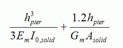
Which can also be expressed as: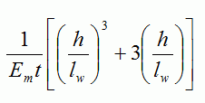 for a solid, rectangular section.
For a fixed-fixed Pier, the relative deflection neglecting openings,∆solid F, is calculated using:
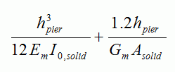 Which can also be expressed as:
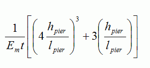 for a solid, rectangular section.
The dimensions used for ∆solid c and ∆solid F as well as I0 are based on gross section properties with an Em based on a fully grouted f’m.
Deflection values for piers or parent piers cannot be used to calculate drift. The sole intent of their use is for lateral load distribution.
From these ∆solid c values, Rsolid can be calculated using:

Using the relative solid deflection values, openings are taken into account when determining the relative deflection of parent piers, ∆parent pier, by subtracting the deflection of the strips and replacing them with the inverse of the sum of rigidities for each pier within the strip.
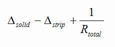 Where Rtotal is the sum of all rigidity values within the strip.
When the relative rigidities are known for each pier, the lateral loads can be distributed. The unfactored load applied to each pier is determined by multiplying the relative rigidity and the unfactored, user-applied loads. These values can be found in the results window under the Load Distribution tab, as seen below in Figure 56: Highlighted relative lateral load percentages in the results window.
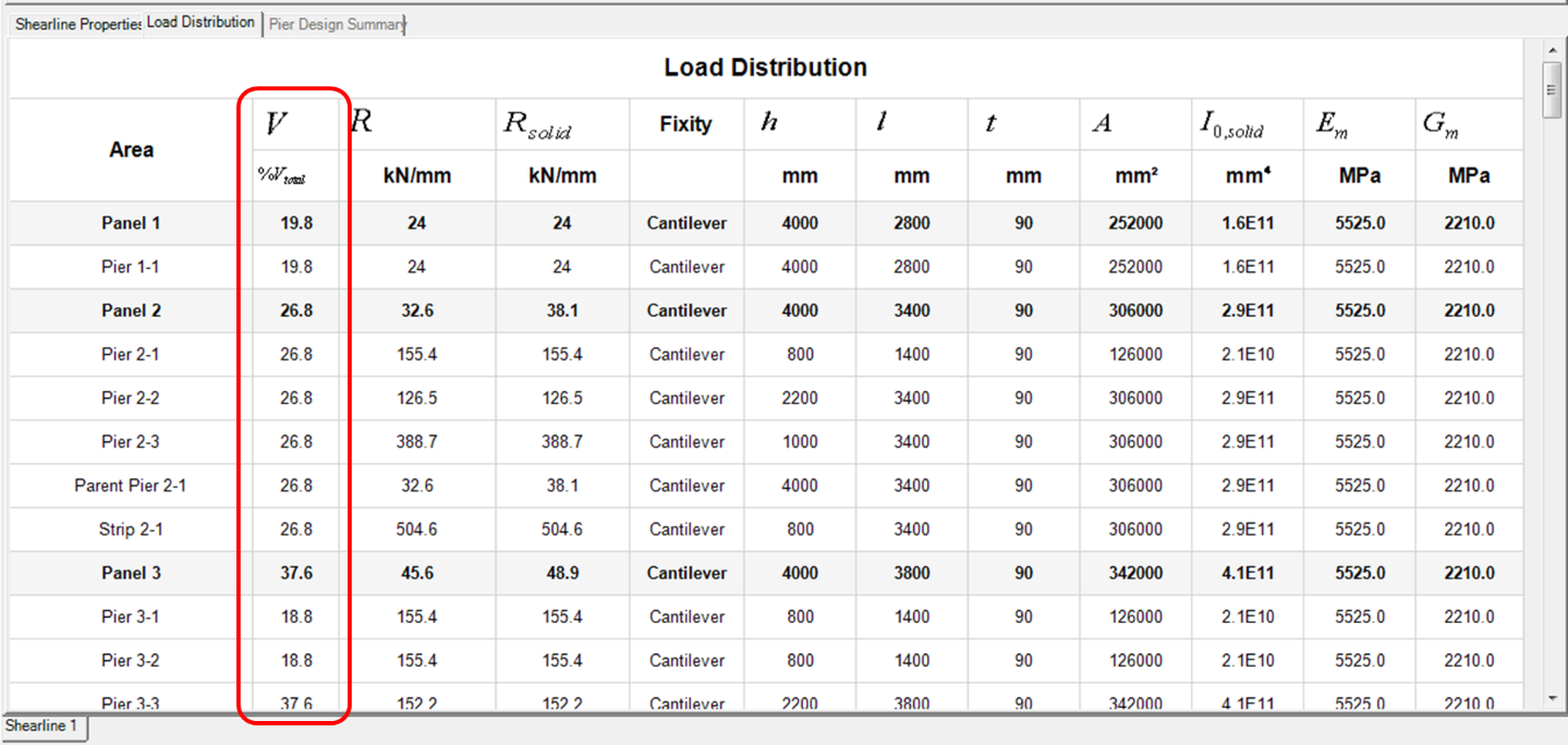 Figure 56: Highlighted relative lateral load percentages in the results window
Load Distribution results can be viewed before performing a design. The loading is shown as a percentage of any lateral loads that are applied. The rigidities used to calculate these initial percentages are based on the smallest, weakest masonry unit. The results seen above in Figure 56: Highlighted relative lateral load percentages in the results window are based on the following shearline shown in Figure 57: Relative lateral load distribution within a shearline.
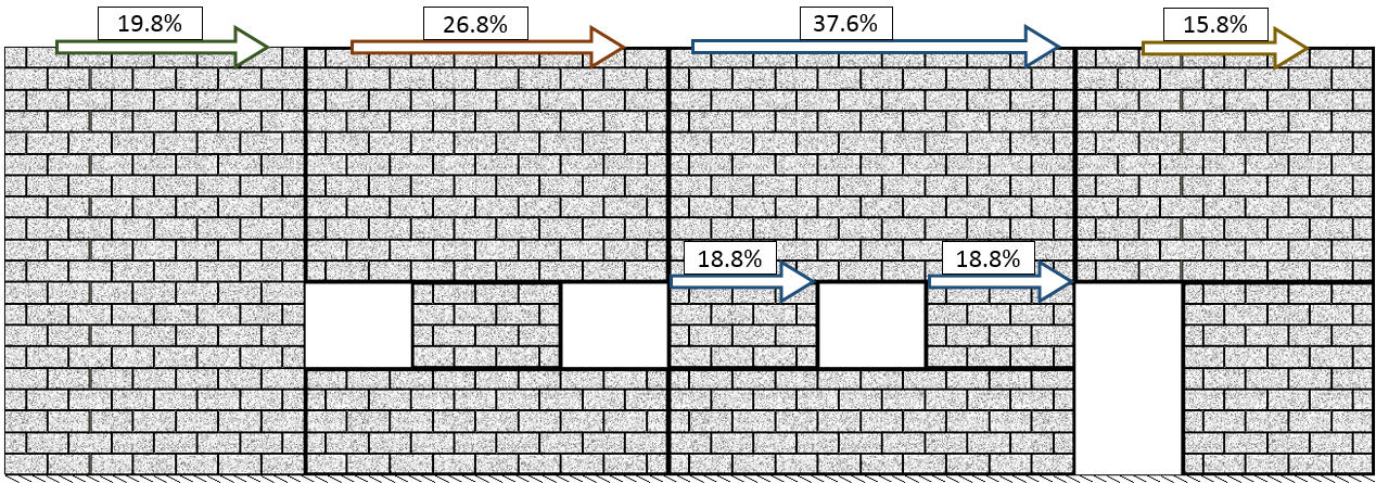 Figure 57: Relative lateral load distribution within a shearline
The %Vtotal values have been added to the drawing to illustrate the path of any applied lateral loading on the shearline. The load is first shared between four Panels and then Piers 3-1 and 3-2 evenly share Panel 3’s distributed load.
Moment Distribution
Lateral loads applied along the top edge of a shearline make their way through various piers to the base of the wall. In many cases, there is a height difference between the top of the pier and the height at which the load was applied. When this occurs, there is an additional bending moment that must be applied to ensure that a pier is designed for the full moment experienced at the base of that pier.
Moments are only distributed to piers that do not share lateral loads with other piers within a strip. Applied moments are calculated using:
VparentPier x ∆h
Where VParentPier is the lateral load distributed to the top of the Parent Pier and Δh represents the difference in elevation between the top of the Pier and the height at which the load is applied or the top of the shearline.
To demonstrate how moments are distributed and applied, refer to the following example shearline shown below in Figure 58: Shearline example with Pier labels and relative lateral load percentages and Figure 59: Distributed moments within a shearline. The loads shown are based on an applied lateral seismic load of 100kN.
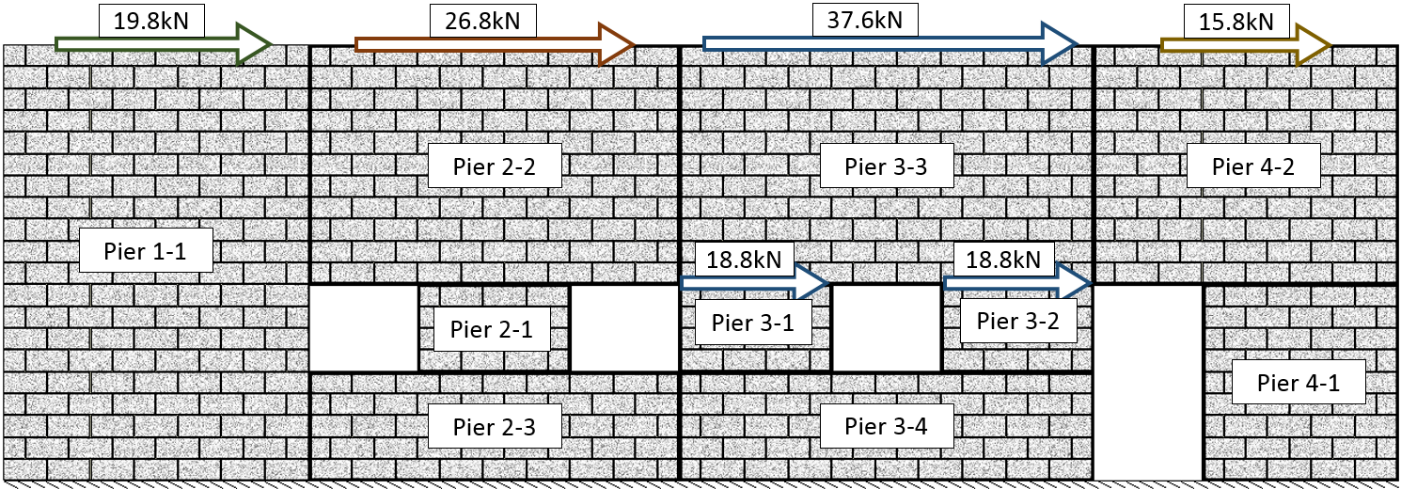 Figure 58: Shearline example with Pier labels and relative lateral load percentages
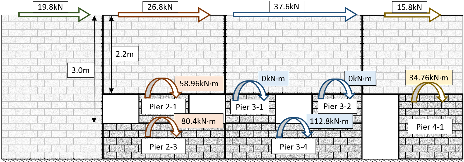 Figure 59: Distributed moments within a shearline
Pier 1-1 extends from the bottom to the top of the shearline where the load is applied. 19.8kN is applied to Pier 1-1. In the Pier tab module, the wall will be designed for Mf = 19.8kN x 4m = 79.2kN*m at the base. There is no need for any additional moment within the Pier tab because the load is applied at the same elevation as the top of the pier.
Pier 2-3 is a similar section at the base of the wall with two openings above it. 26.8kN is applied to Pier 2-3. The Pier is 1m tall and there is a 3m elevation difference between the top of the Pier and point at which the load is applied. An applied moment of 26.8kN x 3.0m = 80.4kN*m is distributed to Pier 2-3 to compensate for this height difference in addition to the lateral point load of 26.8kN. A similar procedure is used for Pier 4-1.
Pier 3-1 and 3-2 share lateral loading within the same strip therefore no additional moment is applied to either pier.
Vertical Load Distribution
The distribution of vertical loads can be summarized in 4 points:
- Vertical loads are distributed downward without any dispersion and through every pier directly below it.
- Vertical loads above openings are replaced by resultant forces on each side of the opening and are distributed further as vertical point loads.
- Vertical loads can be transferred to an adjacent panel if:
- An opening is directly adjacent to a movement joint or,
- A movement joint contains a horizontal offset.
- Vertical point loads applied directly above a movement joint are resisted by the Panel to the left.
Vertical load distribution in MASS™ determines the unfactored loads applied to individual piers. When each vertical load has been distributed through the shearline, the total resultant force from each load is calculated and applied to the top of the pier in the form of an axial load, in kN.
Vertical Load Distribution to Piers below Vertical Loads
MASS™ does not take load dispersion into account when distributing a vertical load. Loads are applied directly to the piers below.
In a simple example shearline with one opening, 4 piers are labelled as shown below in Figure 60: Vertical point load distributed downward to Piers below. The blue arrow at the top of the wall represents the user applied vertical point load and the red arrows represent the same load as applied to Piers 1-2, 1-3 and 1-4. Pier 1-1 does not lie beneath the applied load so it does not experience any of the load.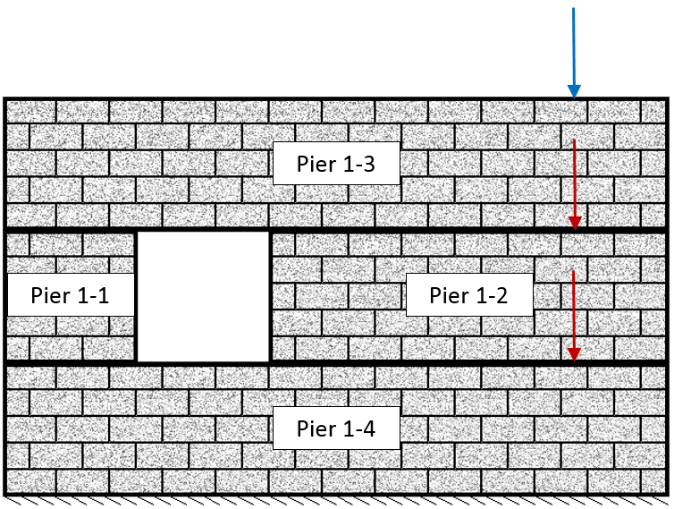
Figure 60: Vertical point load distributed downward to Piers below
Similarly, with uniformly distributed loads (UDL’s), they are resisted by the Piers that lie directly below them. This process can be extended to all other types of loading, as seen below in Figure 61: UDL distributed downward to Piers below.
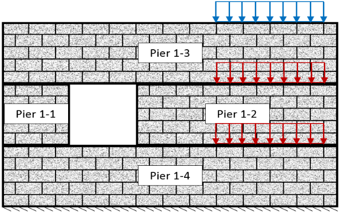 Figure 61: UDL distributed downward to Piers below
Vertical Loads above Openings
When vertical loads are applied or distributed above openings, they are converted to resultant vertical point loads on either side of the opening (see Figure 62: UDL applied above an opening).
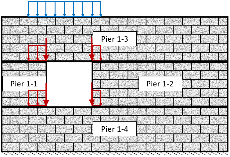 Figure 62: UDL applied above an opening
The portion of load applied or distributed above an opening is converted to a support reaction based on the loads analysis of a simply supported beam. These reaction forces are then applied and distributed through the shearline. Figure 63: Loads above opening modelled as simply supported beam with corresponding reaction forces shows the section of applied load directly above the opening, drawn in blue, and then distributed above the opening, drawn in red.
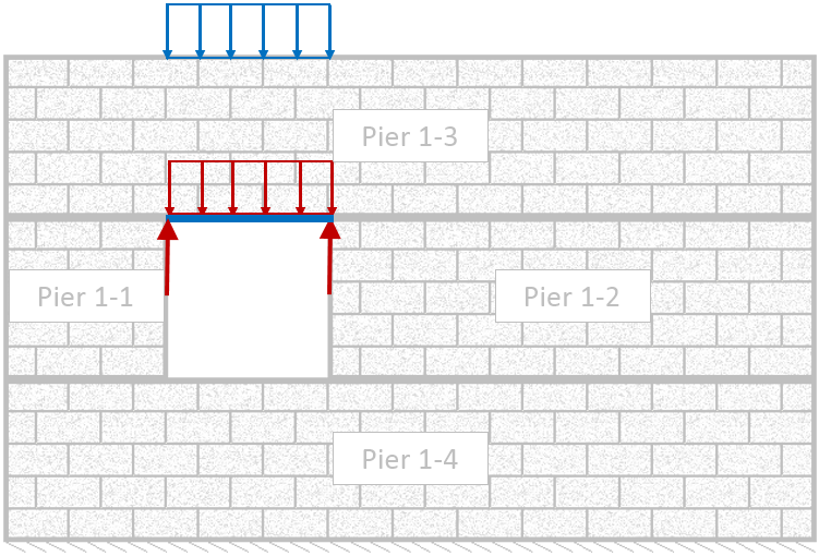 Figure 63: Loads above opening modeled as simply supported beam with corresponding reaction forces
Vertical load distribution is not restricted to UDL’s. Point loads and line loads with varying magnitudes can also be distributed using the same methodology.
Vertical Loads Transferred to an Adjacent Panel
In some cases, movement joints in shearlines can result in vertical loads transferring from one panel to an adjacent panel. This will occur if:
- An opening is directly adjacent to a movement joint or,
- A movement joint contains a horizontal offset
When an opening is adjacent to a movement joint, the vertical force that is distributed through the rest of the shearline is resisted by the panel adjacent to the movement joint. In the example shown below in Figure 64: Resultant forces applied to Pier 1-1 and 2-1, a vertical UDL is applied to Panel 1. When it is distributed to the beam above the opening in Panel 1, the resultant force on the right is distributed to Panel 2.
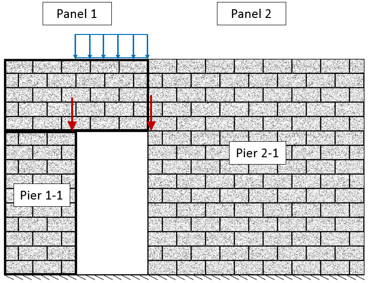 Figure 64: Resultant forces applied to Pier 1-1 and 2-1
Another possible case for vertical loads transferring to an adjacent panel is when there is a movement joint with a horizontal offset as seen below in Figure 65: Vertical load distribution around movement joints with a horizontal offset .
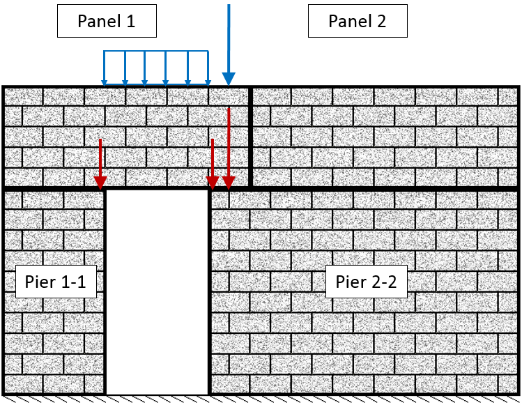 Figure 65: Vertical load distribution around movement joints with a horizontal offset
In the above example, there is a resultant force on the right side of the opening due to the vertical UDL as well as an axial load that is applied above the horizontal offset within the movement joint. Both the applied vertical point load on Panel 1 and the resultant force to the right of the opening are distributed to Pier 2-2.
Point Loads Applied Directly to Movement Joints
When an axial load is created and the location is directly above a movement joint MASS™ will automatically distribute the load through the panel to the left of the movement joint. Figure 66: Axial load applied directly above a shearline movement joint, resisted by the Panel on the left, below, shows an axial load applied directly above a movement joint. In this example, the load will be resisted by Pier 1-1.
Note: Care should be taken to ensure that all applied loads can be properly resisted by the masonry assemblage.
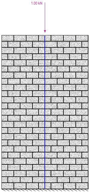 Figure 66: Axial load applied directly above a shearline movement joint, resisted by the Panel on the left
Applying Loads to Piers
When all of the lateral and vertical loads are distributed, they are applied to piers within pier tabs. To see the unfactored loads applied on a pier:
- Select the Pier Tab on the bottom of the screen to the right of the Shearline assemblage.
- Click on the Loads Tab.
- Select loads in the input window to make them appear in the drawing.
MASS™ applies vertical loads by calculating the resultant of each force and applying it to the centre of the cross section at the top of the pier. Resultant forces are taken for vertical line loads and components of self-weight.
There are 3 types of loading shown in the example below, Figure 67: Pier assemblage with vertical loads shown as distributed. The total resultant dead load (shown in red) is simplified to a resultant axial load at the centre of the Pier with a total magnitude of 49.02kN (20kN + 20kN + 4.1kN/m*0.8m + 4.1kN/m*1.4m). The resultant axial load of the live load (green) and snow load (purple) are 13.5kN (0.5*(7kN/m – 2kN/m)*3.0m + 2kN/m*3.0m) and 14kN (10kN/m*1.4m) respectively. Their simplified loads are applied to the Pier tab as shown in Figure 68: Vertical loads expressed as single axial loads applied to a shearline pier element.
A vertical load can be divided several times as it is distributed through a shearline. Distributed components of a user applied load are added together and applied to the pier as a single load. These loads are combined when determining the total magnitude, as seen in the example in Figure 67: Pier assemblage with vertical loads shown as distributed and Figure 68: Vertical loads expressed as single axial loads applied to a shearline pier element.
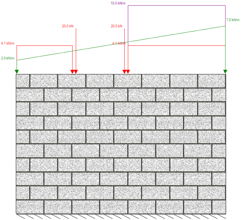 Figure 67: Pier assemblage with vertical loads shown as distributed
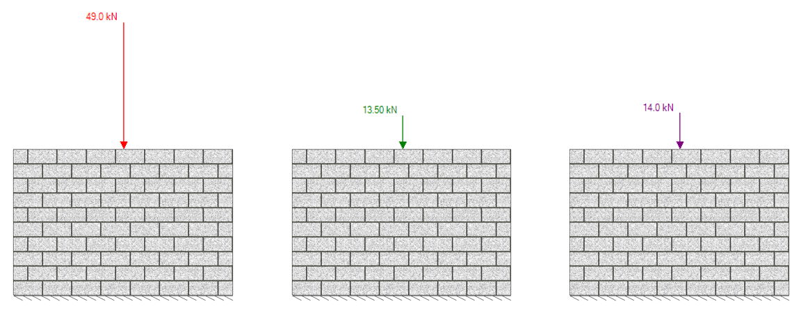 Figure 68: Vertical loads expressed as single axial loads applied to a shearline pier element
Continue Reading: Pier Generation
Was this post helpful?