

Beam Design Strategy
This section provides users with information on how MASS™ obtains a beam design. Specifically, the section discusses the design philosophy employed in the moment and deflection, shear, and bearing design steps. This information allows the designer to manipulate the beam module with ease.
During the moment design step the factored moment, Mf , is compared with the moment resistance, Mr. In order achieve a successful design, Mr ≥ Mf. To meet this requirement the program performs the design by iterating through the bar size, number of bars per layer, number of layers of reinforcement, unit strength, and unit size, in that order. This is summarized in Figure 3-75. At each iteration, the factored moment is compared with the moment resistance.
Note: MASS can only iterate through the properties that are checked-on. Hence, de-selecting all masonry properties and reinforcement configurations, except for one of each type, converts the program into an analysis tool, rather than a design tool. The program simply determines moment resistance, Mr, and compares that value to the factored moment, Mf.
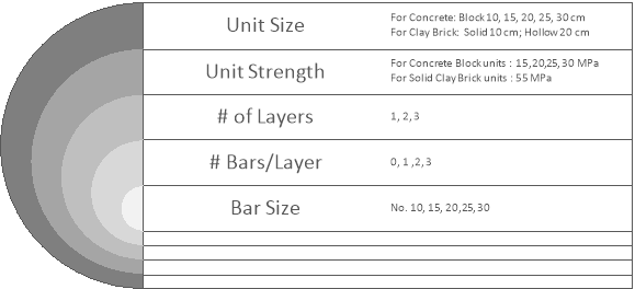
Figure 3-75: Moment and Deflection Design Iteration Hierarchy for Out-of-Plane Wall Module
The program begins by iterating up through the reinforcement configurations, bar sizes, # of bars/layer, and # of layers of reinforcement, while fixing: the unit strength and the unit size. For the initial configuration, the program uses the weakest and smallest unit size selected by users. If the masonry unit properties are left unchanged by users, the default values are: 10 cm, 15 MPa for concrete block; and 10 cm, 55 MPa for clay brick. The number of layers of reinforcement, at the top and bottom of the beam, by default, is one layer, Layer 1. By default, the program can use 1, 2, or 3 bars per layer, at the top and the bottom of the beam.
The program creates a list of all possible reinforcement configurations, based on the parameters selected by users and those that fit within the current block size or brick cavity given the bar separation, side cover, top cover and knockout depth constraints entered by users. The program then sorts the possible steel configurations in terms of total steel area, and cycles through the steel configurations from lowest to highest area. If two steel areas are the same, within 0.1 %, the program chooses the configuration with the greater number of smaller bars, instead of fewer larger bars; and, for the same size and number of bars, the program chooses the configuration with the least number of layers.
The program iterates through the compression steel configurations before the tension steel to start the sequence off with the zero-compression steel condition, which is desirable cost and constructability. The program sets the compression steel configuration to the one with the minimum amount of steel, which in most cases is none. It then cycles through all possible tension steel configurations. If design is not achieved it increments the compression steel area, and then cycles through all the tension steel configurations again.
Note: If the compression steel is not tied, the program does not cycle through the compression steel configurations, as the compression steel does not contribute to the beam moment resistance. The program returns to the next strength if all tension steel configurations failed due to the steel not yielding and/or not providing enough moment resistance.
The iteration continues until a design is achieved, or the compression steel configurations are exhausted. In the latter case, the program iterates up to the next weakest block strength, and begins reiterating through the reinforcement configurations, while fixing the block size.
If a successful design is not achieved with the strongest unit size permitted, the program iterates up to the next smallest unit size, and begins reiterating through the reinforcement configurations. This iteration procedure continues until a successful design is reached, or all block sizes are exhausted.
Note: Due to the large number of iterations the program performs, it may take up to several minutes to reach a successful design. If the program requires more than several seconds to reach a solution, the smaller weaker unit, or smaller bar sizes do not provide enough capacity. In this case, users can easily de-select some of the early iterations in the midst of the design process. This significantly speeds up the program.
If a successful design is found, the program proceeds to design for the deflection of the beam. During the deflection design step the live plus long term deflection, Δ LivePlusLT, is calculated using the beam properties that provided a successful moment design. This deflection is compared with the maximum allowable deflection Δ LivePlusLT Limit, governed by CSA S304-14: 11.4.5. The program also allows users to set an additional total deflection limit, Δ Total Limit, and compares this value with the total immediate plus long term deflection. To achieve a successful deflection design:
ΔLivePlusLT ≤ Δ LivePlusLT Limit and ΔTotal ≤ Δ Total Limit.
In most cases a successful moment design also produces a successful deflection design. However, if the design fails in deflection, the program returns to the moment design iteration procedure. If the moment and deflection design step is successful, the program can proceed to the shear design step.
During the shear design step the shear resistance, at each cell i, Vri, is calculated using the beam properties that provided a successful moment and deflection design. The shear resistance, at each cell i, is compared with the factored shear, at each cell i, Vfi.
To achieve a successful shear design, Vri ≥ Vfi. To meet this requirement the program performs the design by iterating through the stirrup spacing, stirrup configurations, and stirrup size, in that order. This is summarized in Figure 3-76. At each iteration, the factored shear is compared with the shear resistance.
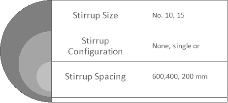
Figure 3-76: Moment and Deflection Design Iteration Hierarchy for Beam Module
The program begins by iterating through the stirrup spacing, while fixing: the stirrup configuration, and the stirrup size. For the initial configuration, the program uses the unit strength and size obtained from the moment and deflection design. If the vertical steel properties are left unchanged by users, the program starts by selecting the ‘None’ stirrup configuration. In this case, the beam is unreinforced, for shear purposes, and thus the stirrup spacing and stirrup size are not a consideration. If this configuration does not yield a successful shear design, the program attempts the design with single leg stirrup configuration, the largest stirrup spacing allowed by design, and the smallest stirrup size.
In MASS™ vertical shear steel can be spaced at variable, Figure 3-43, or uniform, Figure 3-44, intervals along the length of the beam. When uniform spacing is selected, the program uses the smallest spacing calculated from all the cells along the beam. When variable spacing is selected the program first verifies, cell-by-cell, if shear reinforcement is required. If the factored shear is equal or less than half the shear resistance of the masonry, Vf ≤ Vm/2, no stirrups are required, CSA S304-14: 11.3.4.7.1. If the factored shear is greater than half the shear resistance of the masonry, Vf > Vm/2, then the spacing of the vertical shear steel is iterated as previously described, starting with the maximum spacing, Smax, allowed based on the minimum area of shear reinforcement required by CSA S304-14: 11.3.4.7.2.
If a successful design is not achieved with the smallest stirrup spacing, the program iterates to the next stirrup configuration, and begins iterating through stirrup spacing again, while fixing the stirrup size. If a successful design is not achieved with the last stirrup configuration, the program iterates up the next stirrup size, and begins iterating through stirrup spacing again. This iteration procedure continues until a successful design is reached, or all stirrup sizes are exhausted.
If the program has exhausted all vertical steel possibilities, stirrup spacing, configuration, and size, and a solution cannot be found, the program reports a failed design, and returns to the moment and deflection design step to increase the unit strength and/or size. If a successful design is found, the program proceeds to design for bearing, supports, and point loads.
Bearing Design Strategy
During the bearing design step the maximum factored support reaction, Rf, and the maximum factored point load, Ppl, are compared with the bearing resistance, Br. To achieve a successful design Br > Rf or Ppl.
Unlike in moment, deflection, and shear designs, the program does not iterate through masonry units properties, or reinforcement possibilities. In bearing design, the program only verifies the bearing resistance of the beam, based on initial user inputs, bearing length, and the beam design obtained from the moment, deflection, and shear design. The program simply informs users if the bearing area is sufficient to withstand the maximum reaction force at the supports, or the maximum point load applied.
If a successful design is not achieved with the given configuration, it is the users’ responsibility to change the parameters affecting the bearing resistance, bearing length, and bearing width. If a successful bearing design is found, the beam design is completed.
Continue Reading: Out-of-Plane Walls
Was this post helpful?