

Wall Design Steps
Out-of-Plane Wall Design Steps
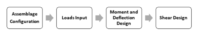
This section provides in-depth detail on the steps necessary to successfully complete an out-of-plane wall design using the MASS software package. There are four design steps necessary to complete an out-of-plane wall design:
Contents
Assemblage configuration is the first design step, where the material properties of the out-of-plane wall are entered or selected. Loads input is the second design step, where the loads and moments are applied to the out-of-plane wall. Using these loads, the program determines the corresponding load combinations. Moment and deflection design is the third design step. At this stage, the program designs the out-of-plane wall such that the moment resistance of the wall exceeds the maximum factored moment determined at the loads input stage. Shear design is the forth design step. At this stage, the program designs the out-of-plane wall such that the shear resistance exceeds the sliding shear and shear due to the factored applied loading.
For instructions on quickly completing an assemblage design, refer to the Wall Module section.
Assemblage Configuration
Assemblage configuration is the first step in developing an out-of-plane wall design. This step allows users to enter the material properties of the out-of-plane wall. To specify the properties of an out-of-plane wall:
Enter the wall dimensions (height in mm)
Select the type of masonry unit (hollow or semi-solid concrete)
Choose the size and strength of the unit
Choose the appropriate end fixity boundary conditions
Provide masonry properties
Provide steel properties
Provide the allowable deflection
Wall Dimensions
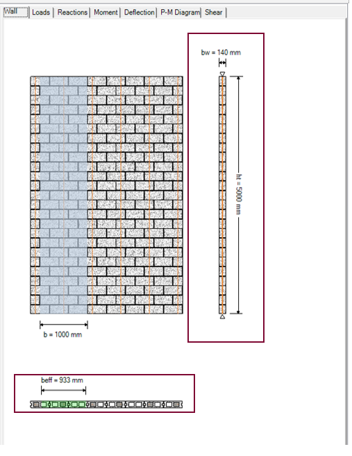
In the case of an out-of-plane wall only one dimension must be entered: the height. Masonry walls can be any height. However a typical wall is about 3-4 m high. It would be very unusual to have a single span wall greater than 20 m high. An out-of-plane wall with a height of 5000 mm has been specified in Figure 4‑1: Entering Dimensions of an Out-of-Plane Wall‑.
Notice that when performing the assemblage configuration design step, the Assemblage Configuration button is outlined in blue.
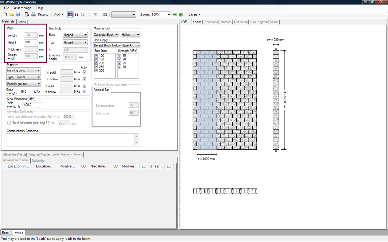
Figure 4‑1: Entering Dimensions of an Out-of-Plane Wall
The program limits the height of an allowable wall due to slenderness effects (CSA S304-14: 7.7.5 and 10.7.3.3). Slenderness effects depend on the ratio of wall height and thickness. This ratio typically ranges from 10-30, so that a 200 mm thick wall (typical wall thickness) would be limited to 2-6 m high. A ratio above 30 is permitted but requires special design procedures which account for slenderness effects. Refer to the Simplified Results section for more details.
For walls that are not modular in height, cut-off blocks are placed at the top of the wall and are outlined in red to indicate a constructability concern. The program always forces the bottom of the wall to start at either the end of a unit or at the half length of a unit.
![]() Note: Dimensions that are non-modular require units to be cut on-site. It up to the designer to decide whether the mortar bed at the top of the wall is considered part of the wall. The program recognises either a modular height or a modular height minus 10 mm, or anything in between, as being composed of full blocks, and uses the smaller value in design calculations.
Note: Dimensions that are non-modular require units to be cut on-site. It up to the designer to decide whether the mortar bed at the top of the wall is considered part of the wall. The program recognises either a modular height or a modular height minus 10 mm, or anything in between, as being composed of full blocks, and uses the smaller value in design calculations.
Below the height textbox is the textbox for the thickness of the out-of-plane wall. This textbox is grey and therefore disabled. The thickness of the out-of-plane wall depends on the masonry unit size selected. The upper limit on the wall thickness is the thickness of the largest block permissible which is typically 290 mm (unless a custom size is added to the masonry unit database). The lower limit on the wall thickness for a single-wythe wall is indirectly imposed for reinforced walls by the need to fit vertical steel in block width. The lower limit for unreinforced masonry is the smallest block size in the masonry unit database. Upon the completion of the moment and deflection design step, (or as soon as users select only one masonry unit size and strength), the masonry unit size used in the design is displayed in this textbox (see for example, Figure 4‑19: Moment Design (Successful)).
Below the thickness textbox is the textbox for the design length of the out-of-plane wall. This textbox is grey and therefore disabled. Masonry walls vary significantly in length depending on the size of project and also on the building layout. Windows, doors, corners, etc. drastically affect the length of masonry walls within a project. For a typical school, walls can range from 600 mm to 8000 mm in length. To simplify the design procedure, the program designs a wall with a representative design length of 1000 mm. This design length is shown in the wall drawing using blue shading (refer to Figure 4‑1: Entering Dimensions of an Out-of-Plane Wall‑). This is a common practice among designers. A length of 3200 mm is automatically entered into this program, for illustrative purposes. With this length it is possible to illustrate the design length (1000 mm), and the maximum moment steel spacing of 2400 mm (CSA S304-14: 10.15.1.2) comfortably in that space. All dimensions in the program are entered in millimetres.
As soon as the assemblage dimensions are entered, the assemblage drawing is available, as shown in Figure 4‑1: Entering Dimensions of an Out-of-Plane Wall‑. This drawing is updated during each design step to reflect any changes to the out-of-plane wall design.
Type of Masonry Unit
For the out-of-plane wall module, MASS supports the use of concrete blocks only (clay bricks are not included). Block types with the following solidity are provided: hollow, semi-solid, solid, half-high, half-block, and bond block. The default unit types are shown in Figure 4‑2: Choosing the Type of Masonry Unit (Hollow, Solid, or Semi-Solid Concrete Block)‑.
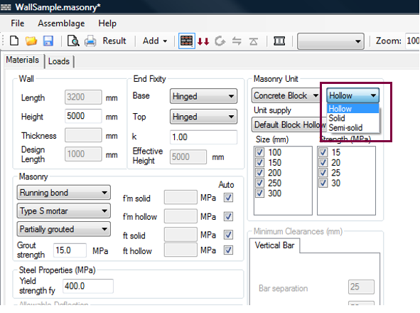
Figure 4‑2: Choosing the Type of Masonry Unit (Hollow, Solid, or Semi-Solid Concrete Block)
Users can also specify the unit supply of the masonry unit. This unit supply list contains default block types based on the solidity selected. For a block with a hollow solidity, the unit supplies available by default are shown in Figure 4‑3: Choosing the Unit Supply‑.
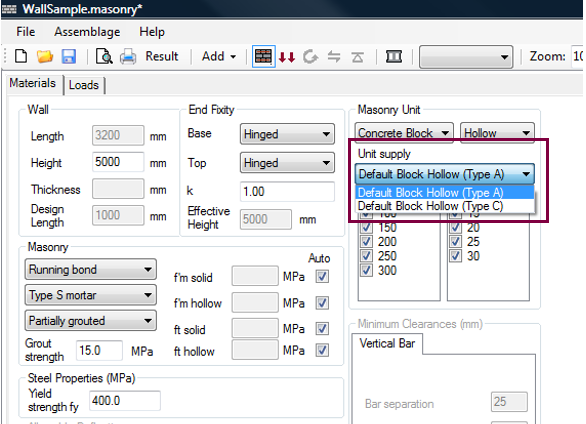
Figure 4‑3: Choosing the Unit Supply
The unit supply lists also includes customized units if they have been entered into the masonry unit database.
![]() Note: In addition to the available block types, users are also able to create a new unit with customized properties using the Masonry Unit Database. Refer to the Masonry Unit Database section.
Note: In addition to the available block types, users are also able to create a new unit with customized properties using the Masonry Unit Database. Refer to the Masonry Unit Database section.
For instructions on how to view the properties of a specific unit, refer to the Masonry Unit Database section. The classification of concrete block properties is governed by CSA A165.1-14 Table 1 to Table 4. For additional information on masonry unit properties refer to page 144 of [1].
Size and Strength of Masonry Unit
Nominal dimensions of a concrete block includes ½ mortar bed thickness on each surface, adding 10 mm to each actual dimension. The actual thickness of a masonry unit t , is 10mm less than the nominal thickness. In the program, the size of the unit refers to the nominal thickness (t + 10 mm mortar joint ) of the masonry unit.
The strength selection pertains to the compressive strength of the unit, F’unit. The compressive strength of the unit is the resistance to pressure applied to the net area of the block perpendicular to the bed plane that is applied. Therefore it depends on the compressive strength of the material, the percent solid, and the shape of the unit. This compressive strength of a unit,F’unit, contributes to the determination of compressive strength of the masonry assemblage, F’m (governed by CSA S304-14, Tables 3 and 4). The compressive strength of an assemblage takes into account the mortar and grout.
The unit strengths available for design depend on the supplier, however, the values provided in the program by default are the typical values used in masonry construction. By default, the program leaves all possible sizes and strengths checked-on, as can be seen in Figure 4‑2: Choosing the Type of Masonry Unit (Hollow, Solid, or Semi-Solid Concrete Block)‑.
The program iterates through these possible values, beginning with the smallest and weakest block, and selects the first of these that meets the engineering requirements. The default concrete block sizes available include 10, 15, 20, 25, and 30 cm units. The default block strengths include 15, 20, 25, and 30 MPa.
![]() Note: In some locations in Canada 30 MPa blocks may not be readily available.
Note: In some locations in Canada 30 MPa blocks may not be readily available.
Other strengths are possible and are accommodated by the program through the masonry unit database. MASS does not support using brick units for out-of-plane wall design. Users can also select the specific size and strength of the unit, by checking-off all other unit sizes and strengths.
End Fixity
The end fixity conditions should be specified prior to the application of any loads. For out-of-plane walls, the fixity conditions supported by MASS are summarized in Table 4‑1: End Fixities‑.
|
Base |
Top |
|
Stiff |
Stiff |
|
Stiff |
Hinged |
|
Stiff |
Free |
|
Hinged |
Hinged |
To select the bottom end fixity of an out-of-plane wall, click on the drop-down box marked ‘Base’, as shown in Figure 4‑4: Choosing End Fixities‑. To select the top end fixity of a wall using MASS, click on the drop-down box marked ‘Top’. An out-of-plane wall with hinged-hinged support conditions is shown in Figure 4‑4: Choosing End Fixities. The support conditions chosen are reflected in the out-of-plane wall drawing in the window on the right side, as shown in Figure 4‑4: Choosing End Fixities‑.
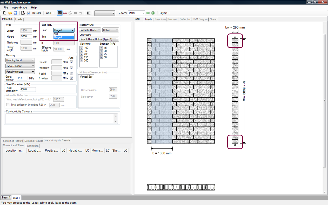
Figure 4‑4: Choosing End Fixities
For the out-of-plane wall module only, the effective length factor, k is provided by the program, as shown in Figure 4‑4: Choosing End Fixities‑. The k values vary depending on the selected fixity conditions, and are obtained from CSA S304-14: Annex B, Table B.1. The effective length factor is reloaded each time end fixity conditions are altered.
The effective height of the wall is also provided by the program, and is used for the calculations for slenderness effects (CSA S304-14: 7.7.5 and 10.7.3.3). The effective height of the wall (CSA S304-14: 7.5.1 and 10.5.1) is equal to the wall height, h , multiplied by the effective length factor,k.
Both the effective length factor and the effective height of the wall are provided in grey textboxes. This indicates the program is providing an output value. These values cannot be directly altered by users.
Masonry Properties
As can be seen in Figure 4‑5: Choose a Bond Pattern‑, users can specify additional masonry properties; such as the bond pattern, mortar type, grouting pattern, compressive strength of the assemblage, tensile strength of assemblage, and grout strength. MASS supports a running bond configuration or a stack pattern configuration for the out-of-plane wall module, as shown in Figure 4‑5: Choose a Bond Pattern‑. The running bond grouting pattern is the default.
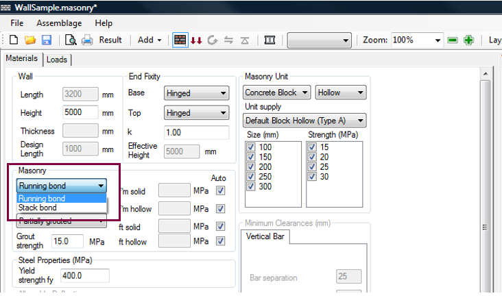
Figure 4‑5: Choose a Bond Pattern
Running bond configuration occurs when blocks in a higher course are placed such that the mid-section of each block is aligned with the vertical mortar joints of the lower course. A stack pattern configuration occurs when blocks align with one another vertically as shown in Figure 4‑6: Bond Configuration (Running Bond and Stack Pattern)‑.
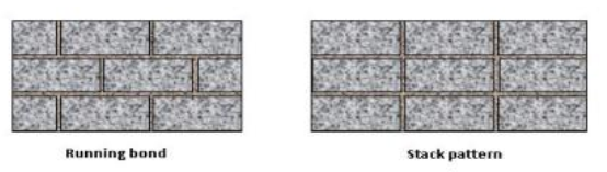
Figure 4‑6: Bond Configuration (Running Bond and Stack Pattern)
Alternative alignments are also permitted in masonry, but are not permitted by MASS. For instance, blocks can be laid with one-third overlap. A one-fourth overlap is however the minimum.
Mortar type in the out-of-plane wall module is selected using drop-down box shown in Figure 4‑7: Choosing Mortar Type‑.
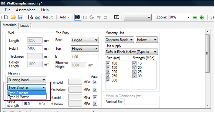
Figure 4‑7: Choosing Mortar Type
In general, there are five grades of masonry mortar (Types M, S, N, O, and K) that are distinguished by their proportions of lime, cement, and sand, and the resulting properties in terms of compressive strength, ductility, and workability. Only Type S and Type N are currently recommended for structural work, and therefore are the only two mortar types available within the program. Type S is a high compressive strength mortar recommended for structural applications. Type N is a more workable but lower strength mortar used for low-stress bearing and veneer applications. Although strong, Type M has high vapour porosity and poor workability. Type O and Type K are primarily for restoration work.
![]() Note: Types M, S, N, O, and K are arbitrary letters, every other letter taken from the words Mason Work and have no meaning in terms of the mortar properties.
Note: Types M, S, N, O, and K are arbitrary letters, every other letter taken from the words Mason Work and have no meaning in terms of the mortar properties.
In the out-of-plane wall module, the grouting pattern is selected using drop-down box shown in Figure 4‑8: Choosing Grouting Pattern‑.

Figure 4‑8: Choosing Grouting Pattern
The grouting pattern depends on the masonry unit type selected by users. For hollow concrete blocks, the grouting patterns permitted are: not grouted, partially grouted, and fully grouted. For semi-solid concrete blocks, the grouting patterns permitted are: not grouted, partially grouted, and fully grouted. For solid concrete blocks, the grouting pattern permitted is: not grouted. The grouting patterns permitted for each block type are summarized in Table 4‑2: Grouting Pattern and Compressive & Tensile Strength Selections Available Based on the Masonry Unit Solidity.
Not grouted simply means the wall does not contain any grout. This grouting pattern is applicable for walls composed of hollow block, semi-solid block, or solid block.
![]() Note: Grout is required for all reinforced cells or cavities. By selecting ‘Not grouted’, users exclude the possibility of a wall with reinforcement.
Note: Grout is required for all reinforced cells or cavities. By selecting ‘Not grouted’, users exclude the possibility of a wall with reinforcement.
Partially grouted refers to some cells being grouted, as shown in Figure 4‑9: Partially Grouted Out-of-Plane‑.
![]()
Figure 4‑9: Partially Grouted Out-of-Plane
This grouting pattern is applicable for walls composed of either hollow block or semi-solid block. In the case of partially grouted walls, only cells that contain reinforcement are to be grouted. Therefore, the grouted cell spacing is equal to the reinforcement spacing.
In fully grouted masonry, all cells must be grouted, independent of the presence of reinforcement or its spacing. This grouting pattern is applicable for walls composed of hollow block, or semi-solid block.
![]() Note: Fully grouting a semi-solid concrete block wall provides the same fire resistance as a fully grouted hollow block wall, but typically provides less strength and is more difficult to construct.Consider using a hollow concrete block instead of a semi-solid concrete block.
Note: Fully grouting a semi-solid concrete block wall provides the same fire resistance as a fully grouted hollow block wall, but typically provides less strength and is more difficult to construct.Consider using a hollow concrete block instead of a semi-solid concrete block.
![]() Note: Choosing a partially grouted or fully grouted grouting pattern does not necessarily result in a reinforced out-of-plane wall. MASS design routine begins by attempting to design an out-of-plane wall without reinforcement because this type of wall configuration is typically cheaper and faster to construct. Users can choose to detail a wall that is specifically reinforced in the moment and deflection design step.
Note: Choosing a partially grouted or fully grouted grouting pattern does not necessarily result in a reinforced out-of-plane wall. MASS design routine begins by attempting to design an out-of-plane wall without reinforcement because this type of wall configuration is typically cheaper and faster to construct. Users can choose to detail a wall that is specifically reinforced in the moment and deflection design step.
To change the grout strength, enter the new grout strength into the textbox, as shown in Figure 4‑10: Entering a New Grout Strength‑. Press Enter on the keyboard.
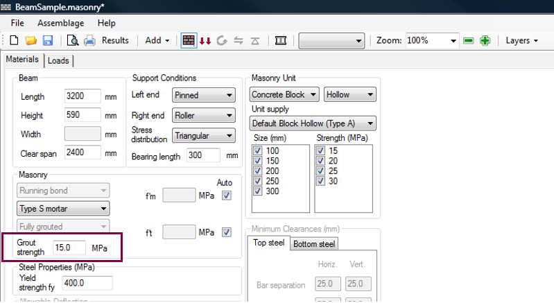
Figure 4‑10: Entering a New Grout Strength
The grout strength entered must meet the requirements of CSA A179. Since CSA A179 allows the designer to specify grout either by proportion specification or by property specification.
The program uses a default value for the compressive strength of grout of 15 MPa. This value is based on the expected compressive strength of in-situ grout, as indicated in Clause 12.4.1.2 of CSA S304-14.
The compressive strength of grout by proportion specification, in accordance to Clause 7.1.2.3 of CSA A179-14, is in the order of 10 to 12 MPa. However, the strength of in-situ grout is higher than the strength of cylinders cast in non-absorbent moulds because suction from the masonry units reduces the water content in the grout. Clause 12.4.1.2 of CSA S304-14 indicates that the in-situ grout strength shall be taken as 1.5 times the 28 d grout cylinder strength test; hence, when using proportion specification the compressive strength for in-situ grout is in the order of 15 to 18 MPa.
![]() Note: Stronger grout (compressive strength above 20 MPa) tends to have a lower water content, and thus is less fluid. As a result, it is often difficult to fill the necessary cells or cavities, resulting in poorer performance. For this reason, using a stronger grout to match the compressive strength of the masonry units, or to satisfy development length requirements, is not recommended. For more information on grout strength, refer to CSA A179-14: 7.2.3.
Note: Stronger grout (compressive strength above 20 MPa) tends to have a lower water content, and thus is less fluid. As a result, it is often difficult to fill the necessary cells or cavities, resulting in poorer performance. For this reason, using a stronger grout to match the compressive strength of the masonry units, or to satisfy development length requirements, is not recommended. For more information on grout strength, refer to CSA A179-14: 7.2.3.
The compressive and tensile strength values of the wall are calculated automatically within the program (Detailed Design) using Table 3, Table 4, and Table 5 in CSA S304, and depend on the masonry unit type selected and the grouting conditions. Upon the completion of the moment and deflection design step, (or as soon as users select only one masonry unit size and strength), the compressive and tensile strength used in the design are displayed in the textbox (as shown, for example, in Figure 4‑19: Moment Design (Successful)).
Users are permitted to override the default compressive and tensile strength values. Depending on the type of unit selected (hollow, solid or semi-solid), and the grouting conditions specified (not grouted, partially grouted, fully grouted), users are permitted to enter only certain types of assemblage compressive strengths. This relationship is summarized in Table 4‑2: Grouting Pattern and Compressive & Tensile Strength Selections Available Based on the Masonry Unit Solidity. The values entered by users must be based on prism tests that have been performed in accordance to CSA S304-14: 5.1 and CSA S304-14: 5.2.
Table 4‑2: Grouting Pattern and Compressive & Tensile Strength Selections Available Based on the Masonry Unit Solidity
| Masonry Unit Type | Grouting Pattern | User Override of Compressive Strengths | User Override of Tensile Strengths |
|
Hollow
|
Not Grouted |
|
|
| Partially Grouted |
|
|
|
| Fully Grouted |
|
|
|
|
Semi-Solid |
Not Grouted |
|
|
| Partially Grouted |
|
|
|
| Fully Grouted |
|
|
|
|
Solid |
Not Grouted |
|
|
Notice in Table 4‑2: Grouting Pattern and Compressive & Tensile Strength Selections Available Based on the Masonry Unit Solidity, for semi-solid masonry units, f’m solid and ft hollow values are used independent of the grouting. Due to lack of supporting research CSA S304-14 takes a conservative approach, and restricts the compressive strength to f’m solid because it is the smaller of f’m solid and f’m hollow. CSA S304-14 also restricts the tensile strength to ft hollow because it is the smaller of ft solid and ft hollow.
To override a compressive strength value, uncheck the ‘Auto’ box, and enter the compressive strength value into the textbox. For example, for a fully grouted hollow wall, users are permitted to enter prism test values for f’m solid, f’m hollow, ft solid, and ft hollow. Uncheck the ‘Auto’ check-box next to each value. Then enter appropriate compressive strength and tensile strength values, as shown in Figure 4‑11: User Override of Compressive and Tensile Strengths‑.

Figure 4‑11: User Override of Compressive and Tensile Strengths
It is common to perform prism tests to gain additional capacity. Because masonry typically fails under compression, designers primarily perform prism tests to determine compressive strength values. However, if users check-off the ‘Auto’ box, the program requires users to provide both the compressive and tensile strengths. It is acceptable to use compressive strength values determined using prism tests, but enter tensile strength values using Table 5 from CSA S304-14. Figure 4‑11: User Override of Compressive and Tensile Strengths The remainder of this chapter utilizes compressive and tensile strength values automatically determined by the program.
![]() Note: The compressive strength values used in the program are limited to 40 MPa. The tensile strengths used in the program are limited to 2 MPa.
Note: The compressive strength values used in the program are limited to 40 MPa. The tensile strengths used in the program are limited to 2 MPa.
Steel Properties
At the stage, the only steel property users are permitted to specify is the steel yield strength. There are three popular grades of steel: 300, 400, and 500. Only the 400-grade is widely available and is used on the vast majority of applications. 300-grade reinforcement bars are available in 10 mm and 15 mm sizes. 500-grade reinforcement bars in all sizes are available through special order to steel mills. The yield strength is defaulted to 400 MPa, as shown in Figure 4‑11: User Override of Compressive and Tensile Strengths. To alter the yield strength, enter a new value in the textbox.
Typically, a designator of W or R is placed by the MPa grade to indicate it can be readily bent/welded (W) or regular steel. Only R steel is widely in stock.
Although there are slight differences in the allowable hook bending radii for W as opposed to R steel, these are not important enough to merit inclusion in the program. All steel used in the program is assumed to be regular (R) steel.
Other vertical steel properties (for example, bar size, bar spacing, etc.) can only be altered once the moment and deflection design step has been completed.
Allowable Deflection
There are two allowable deflection limits that can be altered by users, as can be seen in Figure 4‑12: Allowable Deflection‑.
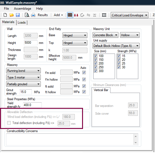
Figure 4‑12: Allowable Deflection
The allowable deflection limits cannot be changed by users until the moment and deflection design step is performed. The minimum clearances (bar separation and side cover) also cannot be changed by users until the moment and deflection design step is performed.
Constructability Concerns
An additional feature of the program is a textbox that provides a feedback of potential constructability concerns. These consist of potential problems that may arise on the construction site due to the particular design the engineer has selected. These constructability concerns are shown in a designated textbox, as well as in the print outs and, where applicable, in the assemblage illustrations.
![]() Note: Constructability concerns are only warnings. The program can provide a successful design even in the presence of a constructability concern. It is up to the discretion of the designer to adjust the design to ensure the assemblage can be reasonably constructed.
Note: Constructability concerns are only warnings. The program can provide a successful design even in the presence of a constructability concern. It is up to the discretion of the designer to adjust the design to ensure the assemblage can be reasonably constructed.
While constructability concerns initially occur during the assemblage configuration design step, the constructability concerns textbox provides interactive feedback only once the moment and deflection design step has been performed.
At this time, users can proceed to the Loads Input design step. Be aware however, that during this design step the assemblage properties previously selected cannot be altered.
Loads Input
Loads input is the second step in developing an out-of-plane wall design. This step allows users to enter the loads that are applied to the assemblage. Loads are applied in a similar manner for all assemblage types.
- Click on the Loads Input button
 , or on the Loads tab
 - Choose the importance category (low, normal, high, post-disaster)
- Click on Add Load
- Enter in load properties (type, distribution, unfactored magnitude, and units)
Loads Input
There are two ways to begin the loads input design step: click on the Loads Input or the Loads tab. Notice that when performing the loads input design step, the Loads Input button is outlined in blue, as shown in Figure 4‑13: Loads Input Design Step‑. Upon moving into the load inputs design step, the program automatically displays the assemblage drawing (with its applied loads) in the Loads tab in the bottom window.
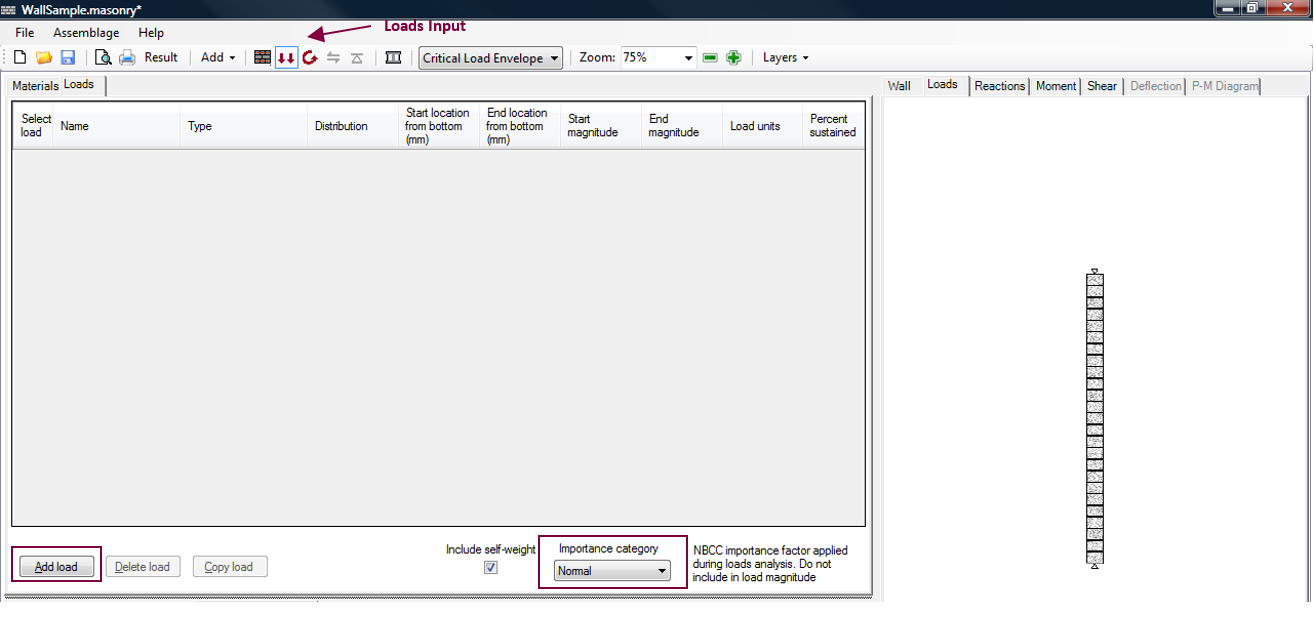
Figure 4‑13: Loads Input Design Step
Notice that because users are performing the loads input design step, the Loads Input button is outlined in blue. During this design step, the material properties should not be changed.
Importance Category
The importance category is selected using the drop-down box under the heading ‘Importance category’, shown in Figure 4‑13: Loads Input Design Step‑. The importance category specifies the importance of a building, which is determined based on the hazard a building failure could pose.
Load Properties
To add a load, click on the Add Load button shown in Figure 4‑13: Loads Input Design Step‑. For more information on adding, copying, and deleting loads, refer to the Loads Input section.
The program allows for the selection of the following loads for the out-of-plane wall assemblage: dead, live, snow, wind, hydrostatic, earthquake, storage, controlled fluid, and soil. These can be selected using the drop-down box found under the ‘Type’ column.
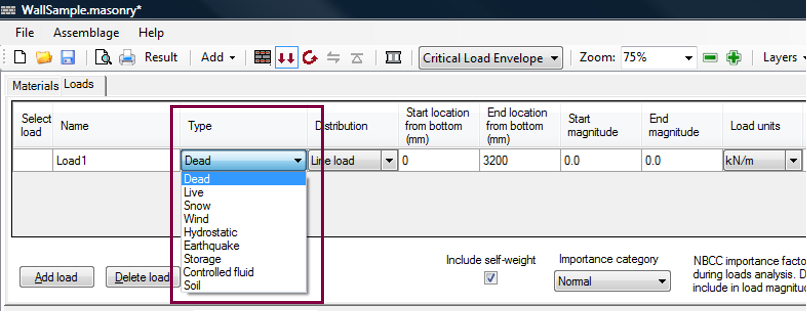
Figure 4‑14: Choose a Load Type
Similarly to choosing a load type, users can choose the load distribution using the drop-down box found under the ‘Distribution’ column. The load distribution opportunities are extensive. Load distributions that can be applied to an out-of-plane wall include point loads, line loads (uniformly distributed, triangular, and trapezoidal), moments, and axial loads. The possible distributions permitted depend on the assemblage.
Although out-of-plane walls can experience an array of load distributions in the vertical direction, since this program is designing a one metre strip only, this MASS requires only an axial load distribution (which is treated as a vertical point load). The designer is responsible for summarizing any area loads into an equivalent axial load.
![]() Note: MASS does not allow for eccentric loading in the vertical direction, that is, the centre of loading in the y-direction is considered to be in the centre of the wall section. Instead, eccentricity of the vertical loads can be taken into account indirectly, by applying a moment to the wall.
Note: MASS does not allow for eccentric loading in the vertical direction, that is, the centre of loading in the y-direction is considered to be in the centre of the wall section. Instead, eccentricity of the vertical loads can be taken into account indirectly, by applying a moment to the wall.
In the out-of-plane wall module, the program allows users to enter a start and end location for both the location of a line load, and the unfactored magnitude. This provides a large versatility in the type of loads that can be applied. In Figure 4‑15: Entering Load Properties‑, an unfactored line load of 1kN/m is applied along the height of the wall (beginning at 0 mm and ending at 5000 mm). An axial load of 7 kN/m is applied at the top of the wall. Notice that the units of the axial load are in kN/m. For the out-of-plane wall module, the program designs a 1 metre strip of the wall.

Figure 4‑15: Entering Load Properties
![]() Note: The start and end magnitude of a line load must be of the same sign. To place a line load that has a start magnitude of -5 kN and an end magnitude of 5 kN, users are required to split the load into two line loads.
Note: The start and end magnitude of a line load must be of the same sign. To place a line load that has a start magnitude of -5 kN and an end magnitude of 5 kN, users are required to split the load into two line loads.
![]() Note: According to MASS sign convention, a west-to-east (left-to-right) load is considered a positive load, as is a downward axial load. A moment applied in the clockwise direction is considered a positive moment.
Note: According to MASS sign convention, a west-to-east (left-to-right) load is considered a positive load, as is a downward axial load. A moment applied in the clockwise direction is considered a positive moment.
The units of the load can be specified using one of the following units (kN/m, N/m, lb/ft, or kip/ft) simply by selecting the drop-down box under the ‘Load units’ column.
A specific applied load can be viewed under the Loads tab by clicking on ‘Selected Load’ box of that particular load. Multiple loads can be viewed by holding down Shift key, and selecting the loads to be displayed. Figure 4‑15: Entering Load Properties‑ shows two selected applied loads that are displayed in the Loads tab. The applied loads that are being displayed are highlighted in blue in the input table. In the loads drawing, the load colours correspond to the load types (refer to A Complete Wall Design).
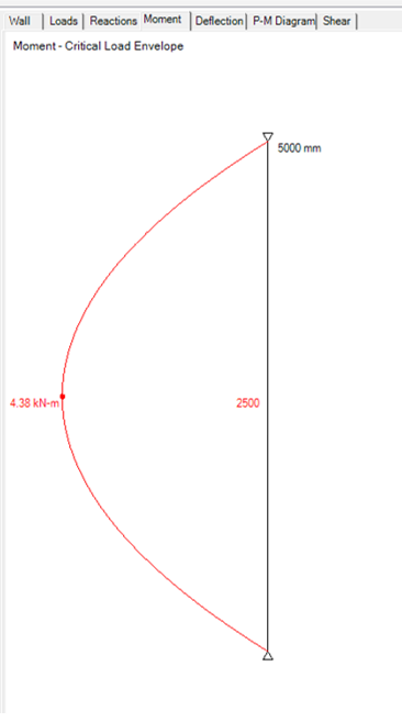
Critical Load Envelope
With each new load added, the program uses the Importance category selected to determine the corresponding factored load combinations based on CSA S304-14: 4.2.2. To view all applicable load combinations click on the Critical Load Envelope drop-down box, as shown in Figure 4‑16: Critical Load Envelope.
Figure 4‑16: Critical Load Envelope
Notice that the drawings under the Reactions, Moment, and Shear tabs, as well as the data in the Loads Analysis Results tabs change to reflect the selected load combination. For instructions on viewing loads analysis results for different load combinations, refer to Loads Analysis Results.
The critical load envelope is the default setting. To create the critical load envelope for the moment drawing, MASS takes resulting moment diagram values for all the applicable
The applicable load combinations are the load combinations that are listed in the Critical Load Envelope drop-down box.
load combinations, and creates an envelope based on the maximum positive and negative moment values along the height of the out-of-plane wall.
Self-Weight
To the left of the ‘Importance category’ drop-down box is the option to include a “Percentage of self-weight applied at top of wall”. The percentage is included by default depending on the boundary conditions selected.
| Boundary Condition | Default Percentage |
| Pin-Pin | 50% |
| Fix-Fix | 100% |
| Fix-Pin | 100% |
| Fix-Free | 100% |
Users can choose to exclude the self-weight of the assemblage by selecting 0% in the drop down menu, shown in Figure 4‑17: Including the Self-Weight.
Figure 4‑17: Including the Self-Weight
The program calculates an initial self-weight based on the masonry properties selected in the assemblage configuration design step. The self-weight is included as a dead load.
MASS determines the self-weight of out-of-plane walls Psw , total weight along the height of the wall, by adding the weight of the masonry units and the weight of the grout, if applicable.
For walls that are not grouted, only the weight of the units is considered; and it is calculated as follows:
Psw = ( hw – h)[%solid x t x γunit x 1000] x 9.81
where hw is the height of the wall, h is the height from the base of the wall to the critical course, t , is the thickness of the wall, γunit is the density of the unit, and, %solid is percentage of the volume of the block that is solid material (as opposed to the cells).
For fully grouted walls, the self-weight of the wall includes the weight of the grout in every cell along a 1 metre strip. For reinforced fully grouted walls, all cells are grouted and therefore the self-weight is independent of the bar spacing. In this case, the self-weight of the wall is determined as follows:
Psw = ( hw – h){(%solid x t x γunit x 1000) + [(100- %solid ) x t x 2350 x 1000]} x 9.81
For partially grouted walls, the grout is only placed at the location of vertical reinforcement. As a result, the self-weight of the wall is affected each time the spacing of the reinforcement is changed. This in turn alters the factored axial load for any load combination that includes a self-weight (that is, a dead load). For partially grouted walls, the self-weight of the wall is determined as follows:

The ![]() term determines the compression zone length per metre of wall, where Sbar is the spacing of the vertical reinforcement, and Lunit is the length of a single block.
term determines the compression zone length per metre of wall, where Sbar is the spacing of the vertical reinforcement, and Lunit is the length of a single block.
In MASS, for a partially grouted wall, all grouted cells contain reinforcement.
Notice, the weight of the reinforcing bars is not included in the self-weight calculations.
The self-weight of a wall depends on the masonry unit size, and the grouting condition. It is therefore likely that the self-weight of the wall will change during the moment and deflection design step or the shear design step, while the program iterates through all the selected masonry and vertical steel properties. In reinforced partially grouted walls for example, the grouted is only placed at the location of vertical reinforcement. As a result, the self-weight of the wall will be affected each time the spacing of the reinforcement is changed. Notice, a partially grouted wall with a vertical bar spacing of 1200 mm contains less grout then the same partially grouted wall with a vertical bar spacing of 800 mm.
Moment and Deflection Design
Moment and deflection design is the third step in developing an out-of-plane wall design. In this step the program iterates through the selected parameters and designs an out-of-plane wall such that the total moment resistance due to masonry and the reinforcement is greater than or equal to the largest moment at the critical section of the out-of-plane wall, for any load combination of input loads. The moment resistance is calculated for each load combination by setting the factored axial load equal to the axial resistance and solving for the corresponding moment resistance. Slenderness effects are taken into account where applicable. The deflection is calculated using the applicable load combinations.
In order run the moment and deflection design:
- Click on the Moment and Deflection Design button
 , as shown in Figure 4‑18: Moment and Deflection Design Step‑.

Figure 4‑18: Moment and Deflection Design Step
Notice that when performing the moment and deflection design step, the Moment and Deflection design button is outlined in blue. Notice, also, that prior to running the moment and deflection design step, the allowable deflection box is disabled. The minimum clearances box is also disabled, and there is no location where users can specify the vertical reinforcement properties until the moment and deflection design step has been run.
Moment and Deflection Design: Successful Design
Highlighted in green are the masonry unit properties and the steel properties that provide a successful design, as can be seen in
Figure 4‑19: Moment Design (Successful)‑. Users cannot alter the vertical steel properties (including the minimum clearances) until the moment and deflection design step has begun. Notice, also, that the design selections are reflected in the out-of-plane wall drawing.
Figure 4‑19: Moment Design (Successful)
![]() Note: The ‘Vertical Steel’ box is disabled if the grouting pattern selected is not grouted, because grout is required to anchor vertical steel.
Note: The ‘Vertical Steel’ box is disabled if the grouting pattern selected is not grouted, because grout is required to anchor vertical steel.
The status bar at the bottom of the page informs users whether or not a successful design is found. The Simplified Results → Moment tab provides summarized moment results for every load combination. For more information on reading the simplified results provided in the Moment tab or the Deflection tab refer to the Simplified Results section.
For fully grouted wall, by default, the number of bars per cell is none. That is, the program attempts to design an unreinforced wall first. If the wall does not provide enough capacity, or does not meet seismic reinforcement requirements, then vertical reinforcement is included into the design. The program uses the smallest number of bars per cell available, the smallest bar size available, and the largest spacing available that produces a successful design. For more information on the design strategy of the program, refer to the Moment and Deflection Design Strategy section.
![]() Note: Due to the large number of iterations the program performs, it may take up to several minutes to reach a successful design. If the program requires more than several seconds to reach a solution, the smaller weaker blocks, or larger spacing and smaller bar sizes do not provide enough capacity. In this case, users can easily de-select some of the early iterations in the midst of the design process. This will significantly speed up the program. Refer to the Moment and Deflection Design Strategy section for more details.
Note: Due to the large number of iterations the program performs, it may take up to several minutes to reach a successful design. If the program requires more than several seconds to reach a solution, the smaller weaker blocks, or larger spacing and smaller bar sizes do not provide enough capacity. In this case, users can easily de-select some of the early iterations in the midst of the design process. This will significantly speed up the program. Refer to the Moment and Deflection Design Strategy section for more details.
Upon the completion of a successful or unsuccessful moment and deflection design, users may wish to alter the design provided by the program. Under the Materials tab, users can change any of the material properties previously entered or selected. The program automatically re-triggers the moment and deflection design step if any of the check-box material selections are altered. For new values that are entered into a textbox, enter the new value, and then press Enter on the keyboard to re-trigger a design.
![]() Note: To add new loads, click on the Loads tab to return to the loads input design step. It is necessary to repeat the moment and deflection design step.
Note: To add new loads, click on the Loads tab to return to the loads input design step. It is necessary to repeat the moment and deflection design step.
Users can now also change the vertical steel properties used in the design, as shown in Figure 4‑19: Moment Design (Successful)‑. To alter the vertical reinforcement along the length of the out-of-plane wall:
- Select the vertical steel placement (symmetric or non-symmetric)
- Select the seismic category
- Select the number of bars per cell
- Select the bar size
- Select the bar spacing
The ‘Symmetric’ check-box is located at the top of the ‘Vertical Steel’ box, as can be seen in Figure 4‑19: Moment Design (Successful)‑.
By default, the ‘Symmetric’ check-box is checked-on. When the ‘Symmetric’ check-box is checked-on, any reinforcement steel in the wall is centred about the width or thickness of the wall, as shown in Figure 4‑20: Symmetric Vertical Steel Placement‑.
|
|
|
Walls may be loaded laterally in either direction. The loading may result in a positive or negative moment. For out-of-plane walls with a single curvature, the offsetting of reinforcement bars is permitted, as shown in Figure 4‑21: Offset Vertical Steel Placement‑.
To allow for offset reinforcement, the ‘Symmetric’ check-box should be checked-off. The offset of one bar per cell or two bars per cell is described by users by changing the side cover and bar spacing between bars within a cell.
![]() Note: When the moment drawing produces both negative and positive moments, the reinforcement bars must be placed symmetrically.
Note: When the moment drawing produces both negative and positive moments, the reinforcement bars must be placed symmetrically.
The possible reinforcement configurations are summarized in Table 4‑3: Vertical Reinforcement Configurations‑.
Table 4‑3: Vertical Reinforcement Configurations
| Possible Reinforcement Configuration |
Placement |
| Symmetric,
One bar per cell |
The bar is placed at t/2, at the centre of the cell. The side cover on either end of the thickness of the unit is equal. In this case the side cover provides a minimum value, and it cannot be used to alter the location of a specific bar. The bar separation has no meaning for this configuration. |
| Symmetric,
Two bars per cell |
Bars are centred in the cell, and placed based on the side cover entered by users (default side cover is 55 mm). The side cover on either end of the thickness of the unit is equal. In this case the bar separation provides a minimum value, and it cannot be used to alter the location of a specific bar. |
|
Non-symmetric , One bar per cell | The bar is placed at a default offset (side cover) of 55 mm. Users can alter this offset by altering the side cover. The bar separation has no meaning for this configuration. |
|
Non-symmetric, Two bars per cell |
The bars are placed at the default side cover value (55 mm), and a default bar separation (25 mm). Users must vary the default side cover and bar separation to offset the reinforcement bars. |
In addition to specifying the placement of the vertical, users can also provide the specific seismic category. Notice that by default the program does not take into account any seismic effects (the seismic category is SC1). To specify a different seismic category, select a different one from the drop down menu (located right below the ‘Symmetric’ check-box).
The seismic category index primarily affects the minimum and maximum limits on the area of reinforcement permitted, and the permitted spacing (CSA S304-14: 16.4, 16.5, and 16.6).
For information on determining the seismic category, refer to the provisions on seismic loading and design in the National Building Code of Canada.
With the seismic category selected, users may wish to alter the current moment and deflection design solution. The program places vertical reinforcement at equal spacing along the length of the web. For example, a wall containing one bar per cell, No. 10 bars, spaced at 200 mm, is shown in Figure 4‑22: Entering a Custom Bar Diameter.
![]() Note: Even if a partially grouted grouting pattern is selected in the assemblage configuration design step, a 200 mm spacing results in a wall that is fully grouted.
Note: Even if a partially grouted grouting pattern is selected in the assemblage configuration design step, a 200 mm spacing results in a wall that is fully grouted.
If users select the fully grouted grouting pattern, all cells must be grouted independent of the reinforcement spacing
After specifying whether or not the reinforcement is placed symmetrically with respect to the width of the out-of-plane, and specifying a seismic category, users can readily change the remaining vertical steel properties.
Select the number of bars per cell. Observe in Figure 4‑22: Entering a Custom Bar Diameter, that by default, ‘None’ and ‘1’ are checked-on. Two bars per cell must be explicitly selected by users in order for this selection to be included as a design option.
![]() Note: If there are two bars placed in one cell, MASS requires that the bars be of the same size. It is not possible for users to select the specific size of the two bars independently.
Note: If there are two bars placed in one cell, MASS requires that the bars be of the same size. It is not possible for users to select the specific size of the two bars independently.
By default, all bar sizes, but No. 30, are checked-on. For a bar size not specified in the check-box list, check-on the ‘Custom diameter’ check-box, and enter the bar diameter into the neighbouring textbox. A custom diameter of 22.225 mm is specified Figure 4‑22: Entering a Custom Bar Diameter. This diameter specified as 22.2225 in millimetres is equivalent to 0.876=7/8 inches. Following the American reinforcement bar sizes, this is the diameter of a No. 7 bar.
Figure 4‑22: Entering a Custom Bar Diameter
Note: Imperial bar sizes must be entered in metric units in the custom diameter textbox.
The custom diameter size is limited to a 25 mm diameter bar. This feature was introduced to allow for imperial reinforcement bar sizes, which are used in some locations in Canada, particularly those in close proximity with the United States border.
To increase the spacing of the vertical bars shown in Figure 4‑22: Entering a Custom Bar Diameter‑, de-select the undesired spacing values, (for example, 200 mm, 400 mm, 600 mm, 800 mm, and 1000 mm).
Vertical bar spacing along the length of the wall, is a multiple of the distance between two adjacent cells (½ the nominal block length).
With these spacing values unavailable, the previous unit size (150 mm) did not provide enough capacity. The program instead, has provided a design that uses a 200 mm unit. With this unit size, a 15 MPa strength unit, and vertical bar spacing of 1200 mm provides a wall with enough capacity to resist the loads applied.
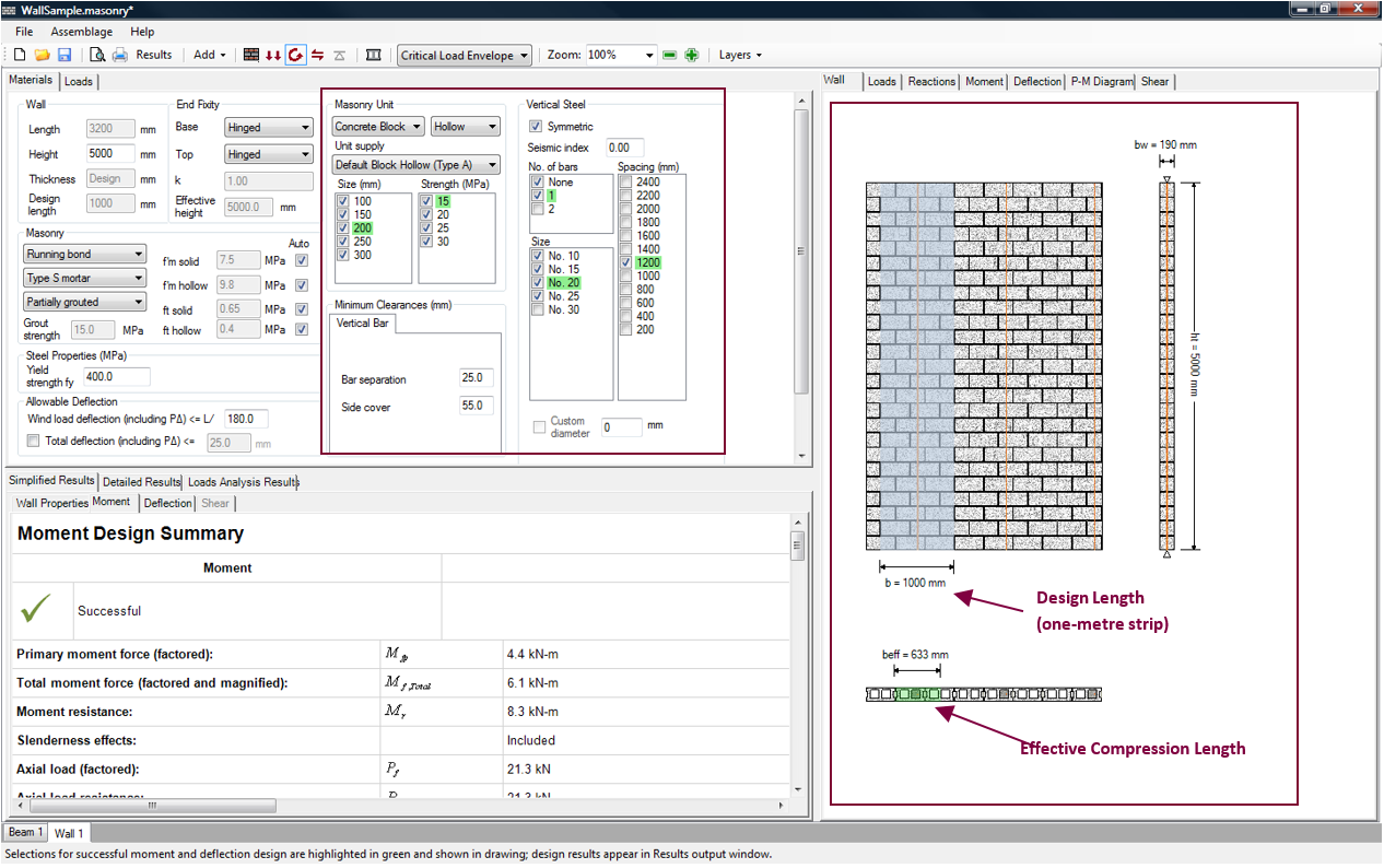
Figure 4‑23: Altering Masonry Properties AFTER the Moment and Deflection Design Step
For partially grouted walls increasing the bar spacing reduces the amount of grout in the wall. This in turn reduces the self-weight of the out-of-plane wall.
Notice, that the 1 metre strip that is being designed for is shaded in blue. The effective compression zone length of that strip, Beff is shaded in green. The effective compression zone length is a reduction in the length of the 1 metre masonry strip. The effective compression zone length is used in the moment and deflection design step calculations. It depends on the placement of the steel bars, and is determined in accordance with CSA S304-14: 10.6.1. For out-of-plane walls that are unreinforced or the reinforcing bars are in compression, the effective width is equal to 1000 mm. For reinforced walls built in stack pattern, the effective compression zone length is also reduced (CSA S304-14: 10.6.1).
Notice also, that by default, the bar spacings from 1400 mm to 2400 mm are de-selected. These spacings are less common. CSA S304-14: 10.15 gives the maximum allowable bar spacing as 2400 mm, when the seismic category is SC1 or SC2 (CSA S304-14: 10.15.1.2), and the lesser of 6(t+10) mm or 1200 mm when the seismic category is SC3 or SC4 (CSA S304-14: 16.4.5.3).
MASS takes a conservative approach by de-selecting the bar spacings from 1400 mm to 2400 mm. Users can readily choose to select these bar spacings to include them as design option as long as the seismic category is SC1 or SC2. For seismic categories of SC3 or SC4, the check-boxes with bar spacings greater than 1400 mm are not available, as can be seen in Figure 4‑24: Seismic Category and Available Bar Spacings ‑.
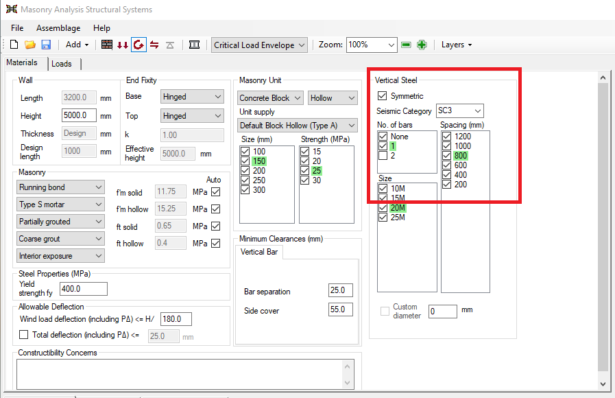
Figure 4‑24: Seismic Category and Available Bar Spacings
Minimum Clearances
MASS places limitations on the possible vertical steel configurations. These possible configurations are based on the current block size as well as the minimum bar separation and side cover. The minimum bar separation and side cover can be manipulated using the ‘Minimum Clearances’ box shown in Figure 4‑25: Entering Minimum Clearances. The minimum bar separation is a user input, with a default value of 25 mm. The minimum side cover is also a user input, with a default value of 55 mm.
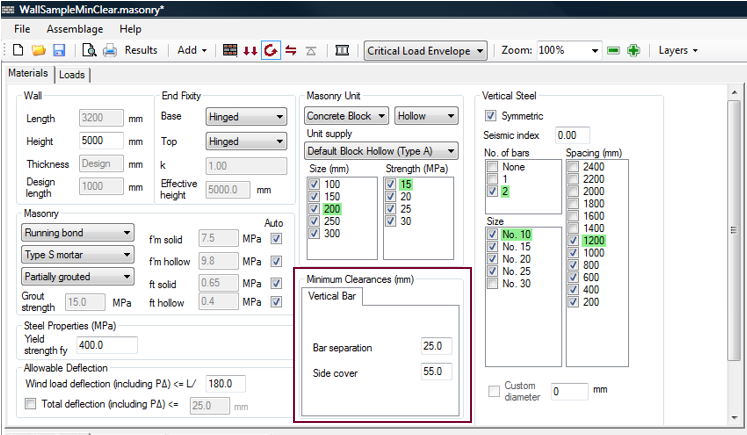
Figure 4‑25: Entering Minimum Clearances
The bar separation entered in Figure 4‑25: Entering Minimum Clearances‑, refers to the separation between the outer surfaces of any two steel bars within a cell. The side cover, refers to the minimum separation between the outer surfaces of the face of the block to the outer surfaces of the nearest reinforcing bar.
The bar separation and side cover are used to determine the location in the cell where the vertical reinforcement steel can be placed, and should meet the requirements for coarse grout. Refer to CSA A371: 8.2.5.7.1 and CSA A165.1-14: 6.2 and 6.3.
Note that the minimum clearance limits are influenced by CSA A371-04: 8.2.5.7.3 because the cover values permitted depends on exposure. The program uses the limits for those walls that are not exposed to weather, as this provides the most possibilities; but users are be able to adjust the limits for weather exposure.
The minimum bar separation and side cover textboxes have a somewhat different function, depending on whether or not the ‘Symmetric’ check-box is checked-on. That is, depending on whether or not the out-of-plane wall is being designed by placing the vertical steel in a symmetric manner or with an offset.
If the out-of-plane wall is being designed with the vertical steel being placed symmetrically with respect the width of the cell, then the vertical steel bars are placed at the specified minimum side cover. The minimum bar separation does not play a direct role in the placement of the vertical steel. It merely provides a minimum distance between the outer surfaces of the reinforcing bars.
For example, a 20 cm unit, with two bars per cell (size No. 10), with a default minimum bar separation of 25 mm, and a minimum side cover (the value entered into the textboxes) is 55 mm as is shown in Figure 4‑26: Minimum Clearance (Symmetric)‑.
Figure 4‑26: Minimum Clearance (Symmetric)
Observe, however, that the minimum bar separation is not the same as the actual bar separation, as shown in Figure 4‑27: Actual Bar Separation‑.
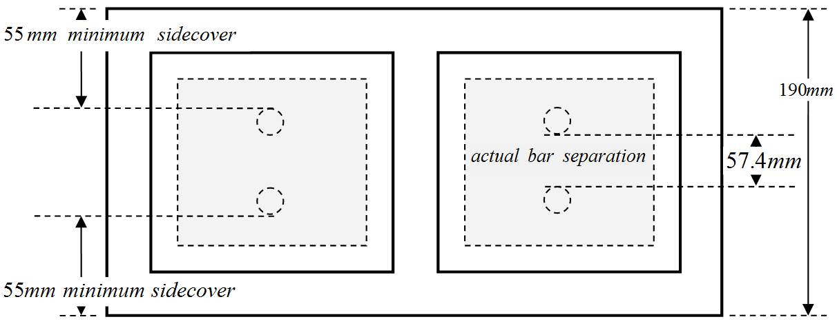
Figure 4‑27: Actual Bar Separation
The actual bar separation is determined using the minimum side cover as follows:
actual bar separation = 190mm – 2(55mm) – 2(11.3mm) = 57.4mm
Internally, the program checks to ensure that the actual bar separation is larger than the minimum bar separation entered by users.
If the out-of-plane wall is being designed by offsetting the vertical steel with respect the width of the cell, then the one offset side is placed at the minimum side cover. The side cover that the program describes varies depending on moment diagram. For a positive moment, shown in Figure 4‑28: Positive Moment Curve‑, the steel is placed on what is typically the tension side of the wall.
|
Figure 4‑28: Positive Moment Curve
|
Figure 4‑29: Vertical Steel Offset |
In this case, the side cover entered in the ‘Minimum Clearances’ box is read from the bottom to the top of the cross-sectional view, as shown in Figure 4‑30: Side Cover (Offset for Positive Moment)‑.
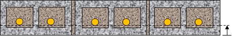
Figure 4‑30: Side Cover (Offset for Positive Moment)
For a negative moment, the steel is also placed on what is typically the tension side to the wall. In this case, the side cover that is entered in the ‘Minimum Clearances’ box is read from the top to the bottom of the cross-sectional view, as shown in Figure 4‑31: Side Cover (Offset for Negative Moment)‑.
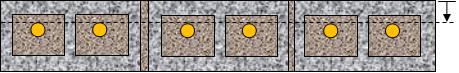
Figure 4‑31: Side Cover (Offset for Negative Moment)
Once again, to offset the steel, the wall must experience either a positive or negative moment, and never both. If the moment experiences a positive and negative moment, the vertical steel must be placed symmetrically within the cell.
In the case when the vertical steel is offset, and there are two bars per cell, the minimum bar separation does play a direct role in the placement of the vertical steel. In this case, the actual bar separation is taken as the minimum bar separation. That is, the minimum bar separation entered by users into the textbox is used to place the second bar.
![]() Note: Minimum clearances cannot be specified for each cell. The bar separation, and side cover specified are applied along the entire length of the wall.
Note: Minimum clearances cannot be specified for each cell. The bar separation, and side cover specified are applied along the entire length of the wall.
Allowable Deflection
Part of the limit state design is checking for serviceability (durability, cracking, vibration, and deflections) under service loads. Excessive deflections may produce cracking of the wall or partitions supported by the wall, misalignment in wall openings (windows and doors), or can be visually uncomfortable to the occupants of the building.
The deflection in masonry out-of-plane walls is a consequence of the loads applied to that wall and the duration of the loads (creep and shrinkage). CSA S304-14: 10.14 indicates the requirements and establishes the procedure to follow to calculate the service load deflection of out-of-plane walls. Once the moment design step is performed, the allowable deflection limits can be altered by users.
There are two allowable deflection limits that can be altered by users; the maximum wind load deflection (including slenderness effects), and the maximum total deflection (including slenderness effects).
Slenderness effects are incorporated into the deflection calculations using the P-Δ method presented in CSA S304-14: 10.7.4.2. Refer to the Moment and Deflection Design Strategy section for more details.
The maximum allowable wind load deflection is governed by CSA S304-14: 10.14.3, and cannot exceed h/180, where h is the single span height of the wall.
Users are permitted to reduce allowable maximum wind load deflection value (that is, increase the denominator). The maximum allowable total deflection is the limit placed on the total deflection, which may be due to lateral wind loads, lateral dead loads, soil pressure, hydrostatic pressure, etc. This is an additional limit that users can place on the deflection, but is not required by CSA S304-14.
To alter the maximum allowable wind load deflection limit, enter a new denominator into the textbox shown in Figure 4‑32: Allowable Deflection. The wind load deflection must be limited in accordance to the provisions specified in CSA S304-14: 10.14.3. The designer can also choose to place an additional limit on the total deflection (all lateral loads applied). To limit the total deflection, check-on the ‘Total deflection (including PΔ)’ check-box, and enter the total deflection limit, in millimetres, as exemplified in Figure 4‑32: Allowable Deflection.
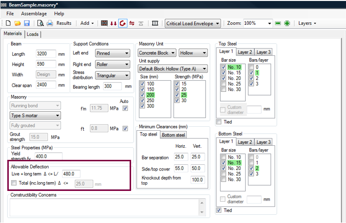
Figure 4‑32: Allowable Deflection
Following the requirements established in CSA S304-14: 10.14, and using the values obtained from moment design, and the values input by the users, the program calculates the wind load deflection and the total deflection (all lateral loads), and compares those values to the maximum wind load deflection allowed by the standard (CSA S304-14: 10.14), and to the maximum total deflection permitted by the user. A successful design is achieved when the calculated deflection values are equal or less than the limiting deflections. If a successful design is not achieved, the program increases the stiffness of the wall according to the design loops (increasing bar size, bar number, unit strength, unit size).
Moment and Deflection Design: Unsuccessful Design
Figure 4‑33: Moment and Deflection Design (Unsuccessful)‑ provides an example of an unsuccessful moment and deflection design.
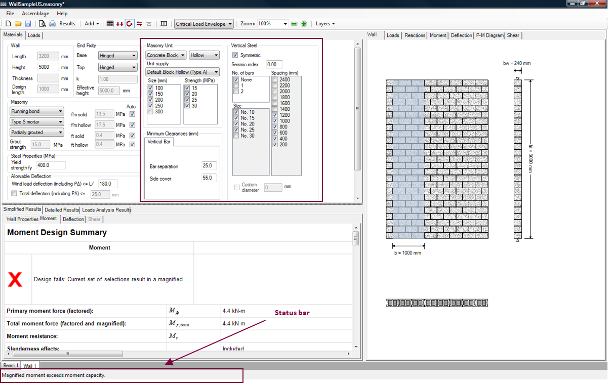
Figure 4‑33: Moment and Deflection Design (Unsuccessful)
Notice that many parameters that were checked-on in
Figure 4‑19: Moment Design (Successful)‑ have been de-selected (by the user), meaning these properties are not to be included as possible parameters for the design. The selected properties did not result in a wall that could resist the applied loads.
The status bar at the bottom of the page informs users whether or not a successful design is found. Notice in the status bar, that the moment design has been performed, notice also, that there are no masonry unit or vertical steel selections that are highlighted in green.
Moment and Deflection Design Results
Upon carrying out a successful or unsuccessful moment and deflection design, the out-of-plane wall drawing is available (displaying the masonry and vertical steel properties used in the design). The simplified and detailed results for the moment and design are also available. The moment and deflection design step is not fully completed until the shear design step is completed. This is because the shear design step may warrant the use of additional vertical steel. Additional steel impacts the existing moment calculations. Refer to A Complete Wall Design for a complete discussion on the moment and deflection design results.
Shear design is the forth step in developing an out-of-plane wall design. In order run the shear design:
- Click on the Shear Design button
 , as shown in Figure 4‑34: Shear Design Step‑.

Figure 4‑34: Shear Design Step
Notice that when performing the shear design step, the Shear Design button is outlined in blue.
Using the wall configuration from the moment and deflection design step, the program calculates the out-of-plane shear resistance and the out-of-plane sliding shear resistance of the wall. It then compares the shear resistance and the sliding shear resistance to the factored shear at the critical section (where the factored shear value is the largest along the height of the wall).
Shear Design Step: Successful Design
The successful design produced after performing the shear design step is shown in Figure 4‑35: Shear Design Step (Successful)‑.
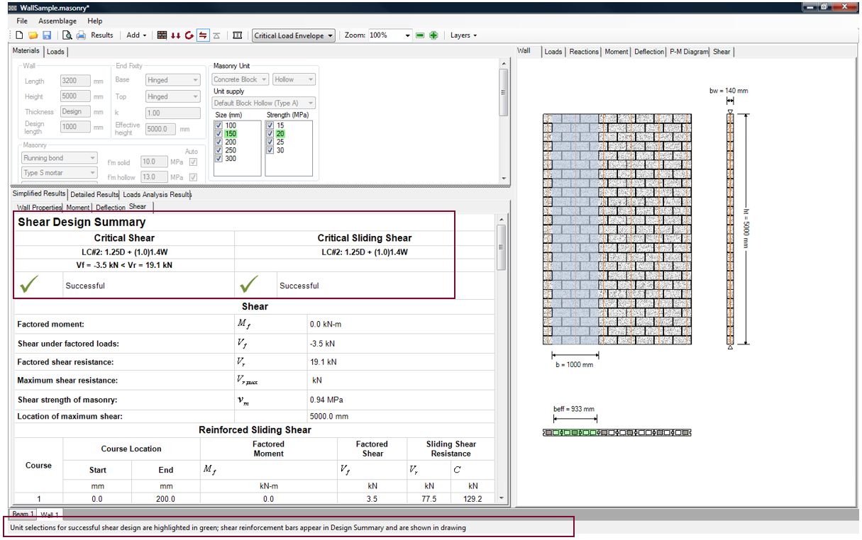
Figure 4‑35: Shear Design Step (Successful)
Notice that upon moving into the shear design step, the program automatically displays the Simplified Results → Shear tab in the bottom window.
Shear Design Step: Unsuccessful Design
If the factored shear
Refer to CSA S304-14:10.10.3 for additional information on calculating out-of-plane shear.
at the critical section (where the shear value is the largest along the height of the wall) is larger than the shear resistance (Vf >Vr ), the current shear design iteration fails. If the factored shear
Refer to CSA S304-14:10.10.5.2 for additional information on calculating out-of-plane sliding shear.
at any course height is larger than the sliding shear resistance at any course height (Vf,i >Vr,i ), the current shear design fails.
For the out-of-plane module only, if the design fails in shear, the program immediately returns to the moment and deflection design step. This is because there is no allowance for horizontal steel in the out-of-plane wall module. Instead, program increments the block size/strength (as discussed in Moment and Deflection Design Strategy section), and redesigns for the moment and deflection and then the shear. For more information on the shear design strategy used in the out-of-plane wall module, refer to the Shear Design Strategy section.
If the program does not highlight in green any of the masonry properties, the shear design failed. The selected properties did not result in a wall that could resist the applied loads. The status bar at the bottom of the page informs users of a failed design, and the Simplified Results → Shear tab shows a red ‘X’. An unsuccessful design can be altered by checking-on more masonry properties (if they are available).
Shear Design Results
Upon the carrying out a successful or unsuccessful shear design, the out-of-plane wall drawing is available (displaying the masonry and vertical steel properties used in the design). The simplified and detailed results for the shear design are also available. The out-of-plane wall design step is completed after the shear design step is completed. Refer to A Complete Wall Design for a complete discussion on the shear design results.
Upon the completion of the shear design step, the out-of-plane wall design is complete.
![]() Warning: Detailing work is left up to the designer. MASS does not account for splice lengths, development length, etc.
Warning: Detailing work is left up to the designer. MASS does not account for splice lengths, development length, etc.
Continue Reading: A Complete Wall Design
Was this post helpful?