

Masonry Self-Weight
Outlining the basics of how MASS looks at masonry and determines the self-weight as a dead load
Contents
While MASS does not consider the differences in weight for the reinforcing bars displacing grout, the software does factor in the differences in density between different masonry unit types (Class A through D) as well as using a density of 2,350 kg/m3 for the grout used to fill those units.
Going from Density to a Force
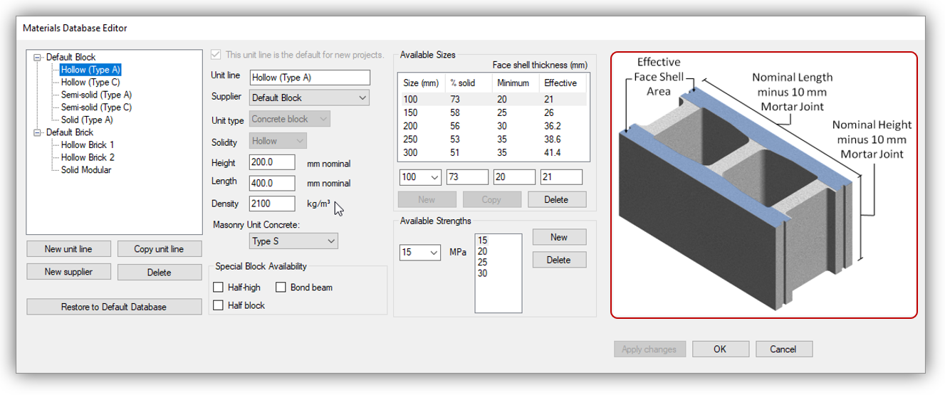
All weight values are determined from density expressed in the form of mass per unit volume. The density for a particular unit used by MASS can be found by opening the materials unit database and selecting the unit of interest. The figure below shows the density of a solid type A masonry unit:
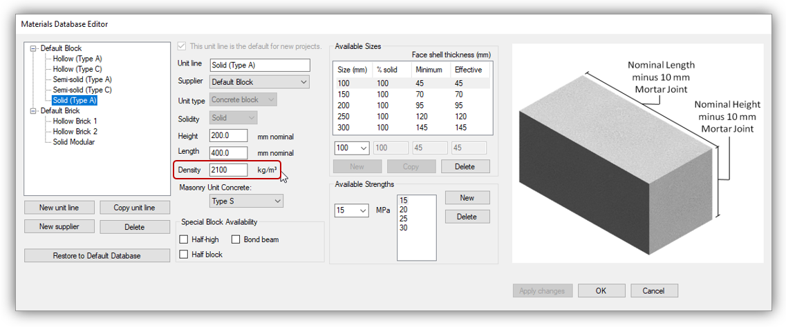 Since unit type can be classified based on density, this solid Type A unit has a density of 2100 kg/m3. The densities for other unit types are shown below:
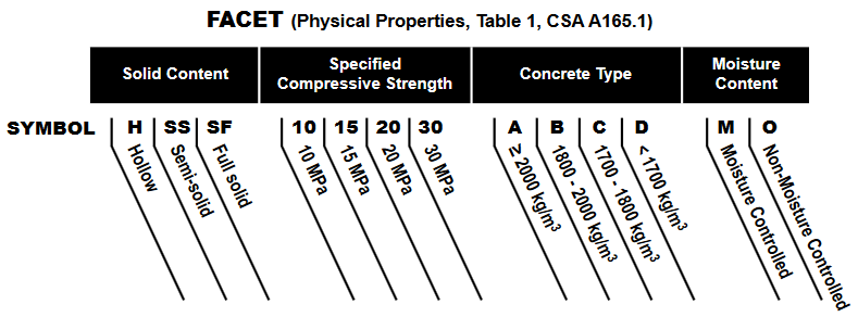
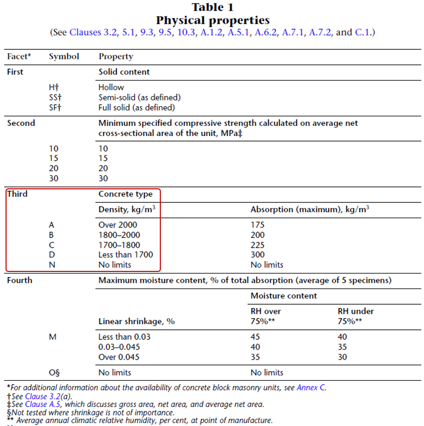 In the interest in being conservative for the most likely design scenarios, the larger end of each range is used by default in MASS, with the density for Type A set to 2100 kg/m3 to be consistent with the CMDC masonry design textbook as well as the CCMPA Metric Technical Manual, linked here for reference. The four facet summary from the linked document is shown below:
Using Newton’s second Law (shown below), this can be converted to a force, per unit volume by multiplying the density by the observed acceleration due to gravity, g.
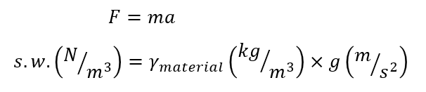 This is why all self-weight formulas are multiplied by 9.81m/s2, converting kg to N.
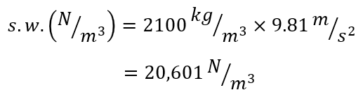 As a result, the density of the Type A unit discussed above can also be expressed as a force of 20,601 n/m3 or 20.6 kN/m3.
Considering Dimensions and Hollow Areas
If dealing with a fictional masonry unit that is a massive 1m by 1m by 1m in size, the self weight is simply equal to 20.6 kN. Show us the mason that can lay those units and we will direct them to where they can enter the world’s strongest man competition!
Masonry assemblages that are designed and built today using traditional units have varying thicknesses and are also not 100% solid within those outer dimensions. Density (mass per unit volume) can be converted to a weight per area of wall by factoring in how thick the wall is as well as how much of that wall is filled solid.
Actual Unit Dimensions
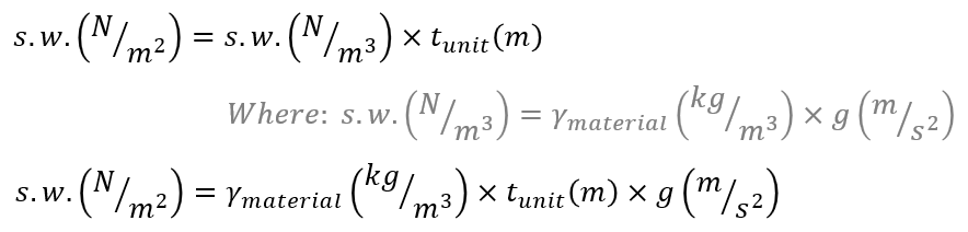
The first component that is needed to go from density to a weight per elevation area of masonry is the thickness of units being used. Multiplying density which is expressed per unit volume by the unit thickness results in a weight per m2 of masonry.
One thing to note while using the unit database is that units are specified using nominal dimensions, rather than their actual dimensions. This is true for height and length, as well as the thickness.
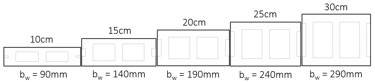 The actual thickness of a 20cm unit is 190mm or 0.19m so the weight per m2 of masonry material in this case is the weight per m3 multiplied by 0.19m.
As a result, density is always multiplied by the masonry unit thickness in all self-weight formulas and calculations performed by MASS.
Percent Solidity
Hollow and semi-solid masonry units are not solid rectangular prisms. They have cells and other areas that can either be left empty or filled with grout. The reference images for each type from the masonry unit database are shown below:
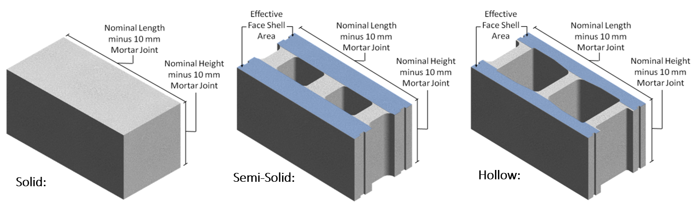 In addition to the hollow cells, there are also frogged ends that are within the outer dimensions but are not occupied by solid material. All of these details are taken into account under the “% solid” property. This value represents the percentage of volume within the outer rectangular dimensions that are filled with solid material. Based on the types of units shown in the figure above, solid units will always have a %solid value of 100% with semi-solid units having a lower percentage and hollow units being even lower.
When dealing with self-weight calculations for solid masonry units, the formulas in the section above are sufficient because there are no voids within the outer unit dimensions to take into account.
The figure below shows where these values can be found and modified within the material unit database as well as the standard percent solid values for each size for the hollow unit type:
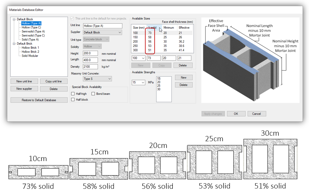
Combined with the unit thickness and percent solidity, a weight per unit volume can be converted to a weight per unit area of wall:
![]()
The same process can be followed for semi-solid units where the percent solid values will be larger than those for their hollow unit counterparts.
Adding Grout to Hollow Masonry
Grout can be added to hollow masonry as part of the design and construction process to encapsulate steel bars required for reinforced masonry design, to add stiffness to the assemblage, or simply as a way to improve the fire resistance rating.
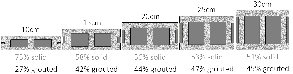
When factoring in the added self-weight contribution of grout, it is assumed for these calculations that grout is able to flow into all of the voids within the masonry unit (this is also very important for the function and performance of the wall). As a result, the percentage of volume occupied by grout is determined using the formula below:
![]()
For the commonly used hollow masonry units of varying thickness, the percent grouted values are shown corresponding to the default values from the software’s material unit database:
Using a grout density of 2350 kg/m3 for the grouted area, the weight per unit area of fully grouted masonry can be calculated using the following formula:

The difference from the earlier equation for hollow masonry is that a second term is needed within the self-weight expression to take the higher material density of grout into account.
Total Self-Weight for Masonry Assemblages
Up to this point, the self-weight expressions for hollow and grouted masonry have been explained on a basis of per unit area of wall. In order to determine the total self-weight of a masonry wall or beam, the total force can be determined by multiplying the self-weight per m2 by the total area (length and height).
For hollow masonry:

For fully grouted masonry:

Combining the two method is useful for cases where the wall is partially grouted.
Partially Grouted Masonry
For partially grouted masonry, self weight can be calculated by simply adding the components of hollow and grouted masonry with their corresponding areas. Since there is also hollow masonry in grouted regions of a masonry wall, this can be simplified to an expression where the weight of the grout is added to the weight of the full masonry wall as if it were hollow.
This is how the self weight equations in MASS are structured, where the weight of the hollow masonry is calculated in the first terms followed by the weight of the grout.
Example Calculations
These brief examples show self-weight calculations with actual dimensions with varying grouting patterns. They are done for a 3m long by 4m tall wall, constructed using a H/15/A/M Masonry unit.
Universal to all of these examples will be the density of a Type A masonry unit: 2100 kg/m3, as well as the solid percentage value for a 15cm unit, taken as the MASS default 58% (leaving 42% volume for the grout to fill, where applicable).
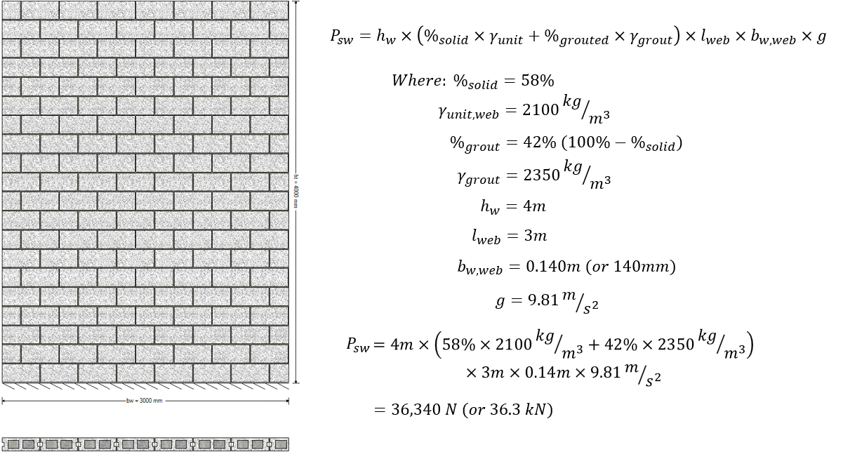
Hollow Masonry
For a hollow masonry wall, the total self -weight calculation is shown below:
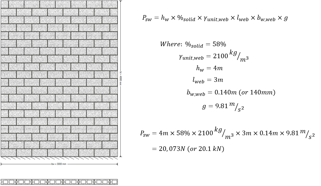
Functionally, this can be broken down to the total outer volume of the wall, multiplied by the percentage that is actually occupied by solid material, multiplied by the weight per unit volume. There is only one term because only one material density is present in the wall.
Fully Grouted Masonry
When grout is added to the wall, the density of grout is taken into account and added to the weight of the hollow wall:
The presence of grout adds a second term for the remaining volume of wall not occupied by the masonry units themselves. In this case, it is the remaining 42% of the available space. Masonry beams are always fully grouted so this expression can be used for all beam designs in MASS. Since the wall in this example is fully grouted, the outer volume for both the block and grout terms is the entire wall but when switching to looking at a partially grouted wall, these dimensions must be further broken down.
Partially Grouted Masonry
Partially grouted masonry walls require that the length dimensions be separated into the masonry unit and grout terms respectively because while the entire length of wall is constructed of blocks, only some of those cells contain grout.
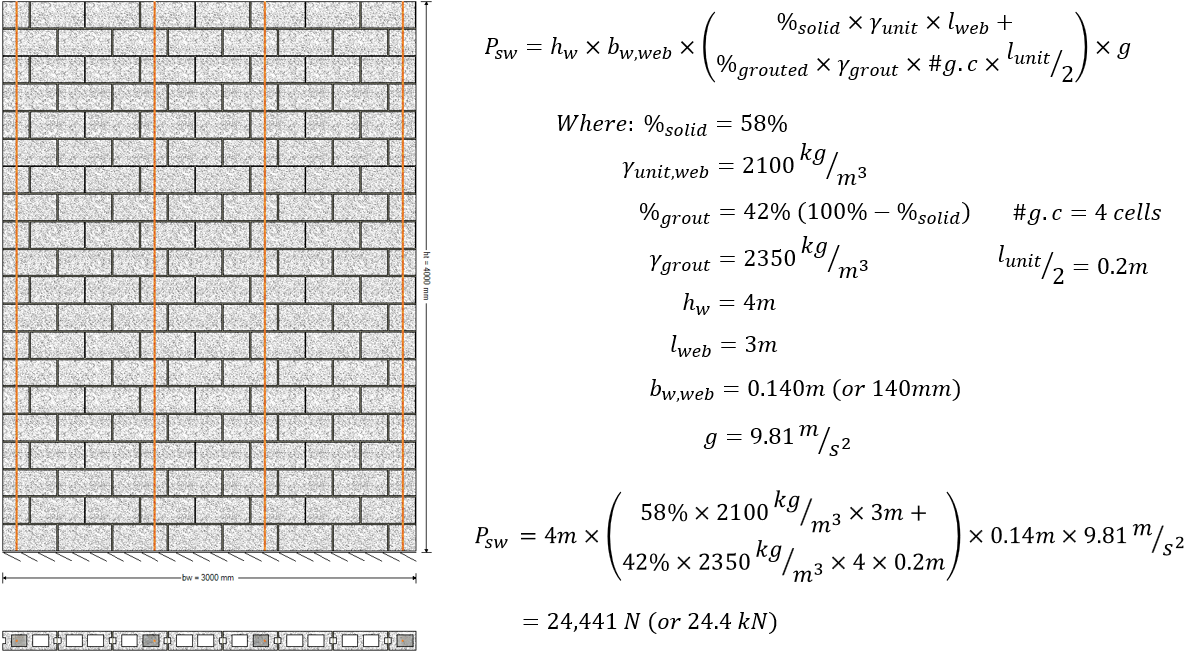
In this example, only four cells, or 800mm length of wall contains grout while the entire length, or 3m, includes the unit density. This is uniform along the entire height of the wall so the sum of both density terms can bu multiplied by the full height of the wall.
Partially Grouted with Bond Beams
The presence of bond beams in a partially grouted wall requires that the density be broken down along the height of the wall in addition to splitting up the length:
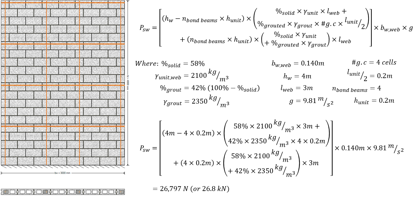
This expression is structured in such a way where the courses of masonry that do not contain bond beams are handled first, looking at the full height minus the bond beam courses, or 3.2m. Within that term, the weight is calculated based on hollow units along the entire length plus the addition of grout in only the grouted portions of that same cross section.
The second main term looks at the remaining height of the wall that was excluded from the first, leaving only the bond beams which are fully grouted, or 0.8m height. The densities used within this term are spread along the full wall length to reflect both the masonry units and poured grout in each cell. At this point, the only uniform dimension along the entire wall is the thickness, which is multiplied at the very end.
Summary of Example Results
A plot of how the self-weight is distributed along the height of a wall is shown below:
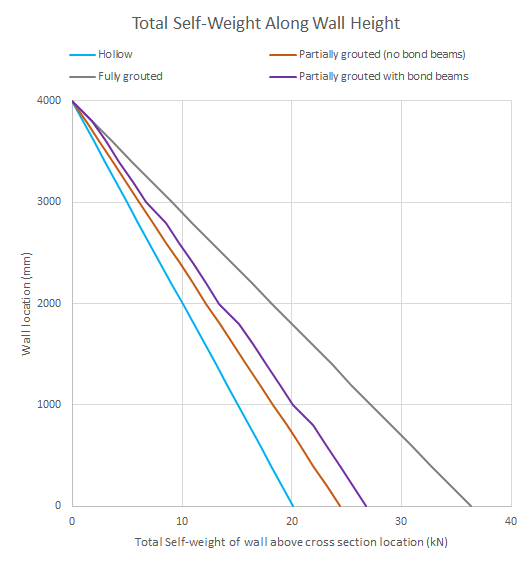
As expected, the partially grouted self-weight distributions lie between the hollow and fully grouted results. Additionally, all of the distributions except for the wall with bond beams have a linear distribution, as each course along the height of the wall has the same cross section and grouting pattern. For the bond beam example, a change in slope matching the fully grouted wall can be seen for only the wall locations where a bond beam is present, reflecting the additional grout.
Continue Reading: Masonry Unit Database
Further Reading
A section is available which lists all of the equations used for self-weight of shear wall calculations. Click here to read more.
Was this post helpful?