

Multi-Storey Load Distribution
Taking the loads applied to a multi-storey shear wall and applying them to each individual shear wall element
Contents
This topic covers the process used by MASS in taking the loads applied on a multi-storey shear wall module and calculating the component that is applied on each shear wall element, within the multi-storey assemblage.
Please be advised that many figures references on this page are large in size and not optimized for mobile viewing. Please contact CMDC, the authorized technical service provider for MASS, with any questions or concerns regarding the accessibility of this page.
Note: There is no mention of load combinations in this section. All loads are distributed unfactored, with their corresponding load type saved in memory for the individual shear walls to factor using each applicable load combination. In many cases, the higher axial load at the lower storeys are critical and govern design compared to the upper storeys where higher lateral loads govern a design. A critical load combination for one element of a multi-storey shear wall may not necessarily be critical for others which is why all shear wall elements are each designed under all load combinations.
Before getting into the specifics of load distribution, it is important to understand the scope of the multi-storey shear wall module.
Multi-Storey Scope Review
With respect to applied loads, the multi-storey module handles designs where loads are only applied at the tops of each floor, similar to how individual shear wall element designs are handled by MASS. For a situation where loads are applied continuously along the height of a wall, such as uniformly applied wind pressure, this is accounted for my applying the total lateral force divided by tributary area. Grouping these line loads into a series of individual lateral point loads, if done properly at the discretion of the designer, should not result in significant changes to the final factored shear and bending moment experienced by the critical section of each shear wall element. This is an engineering assumption left at the hands of the user to account for themselves.
The same is true for axial loads, applied at the tops of each wall, beneath the location where each floor lab sits. While most axial force components are in fact applied at distinct locations along the height of the wall due to the transfer from the floor system, self-weight of the wall elements themselves are technically applied at each location along the height that has any weight at all. If the user leaves the self-weight to be handled automatically by MASS, the software will handle this by determining the exact self-weight force above any critical cross section being designed. If the self-weight option is disabled by the user, they will need to enter discrete, axial, dead load forces on the top of each wall being designed.
 While it is possible to apply an applied moment at the top of a hear wall element, there is no such option in the multi-storey shear wall module. This is because the intended purpose of the applied moment load type is to factor lateral point loads applied to parts of the wall above the shear wall element being considered.
With the multi-storey module allowing the user to model the entire height of their wall, as well as express all of their applied loads within one MASS assemblage, the middle-man step of calculating applied moments is no longer needed. With lateral wind and seismic loads applied at the top of each storey of a structure, MASS will determine the moment at the top of each wall using the method outlined below.
Note: Eccentricities for axial loads are currently outside the scope of the multi-storey shear wall module.
Distributing Axial Loads
Axial load distribution is the simplest because is has no impact on bending moment and shear force experienced within the wall. Each individual axial load that is applied to a multi-storey shear wall is resisted by each shear wall element beneath where the load is applied.
For example, if a 45kN snow load is applied to the top of a four storey shear wall, the design of each storey within the wall will design for that axial load, in addition to all other loads applied.
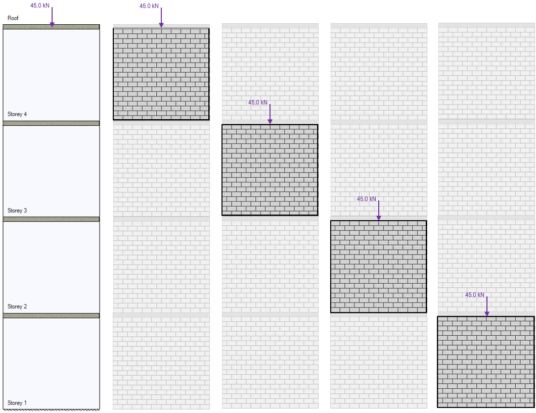
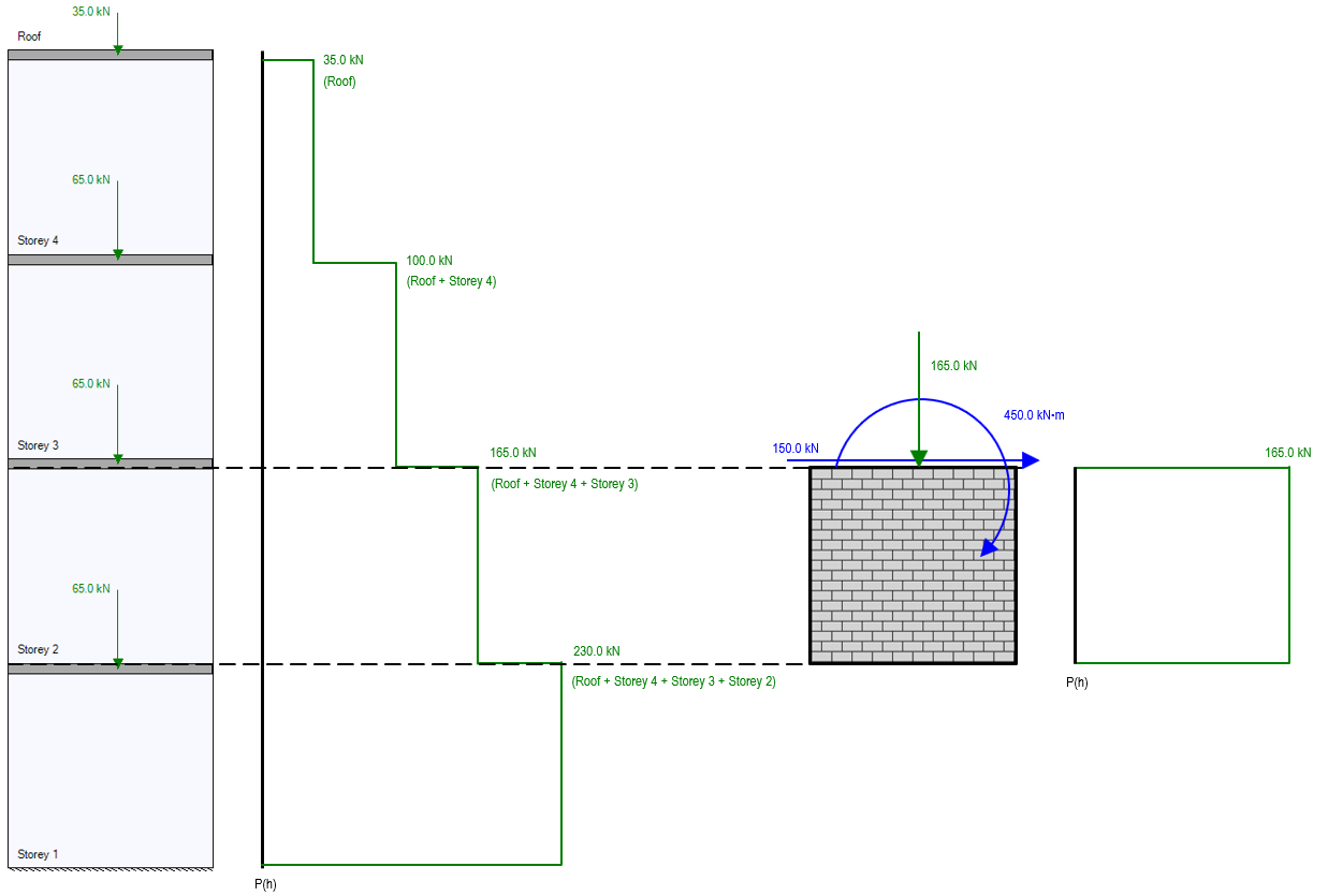
Looking at that same four storey shear wall, if live loads are calculated by the designer and applied as shown in the figure below, the shear walls further down will resist more live loads than the shear walls near the top.
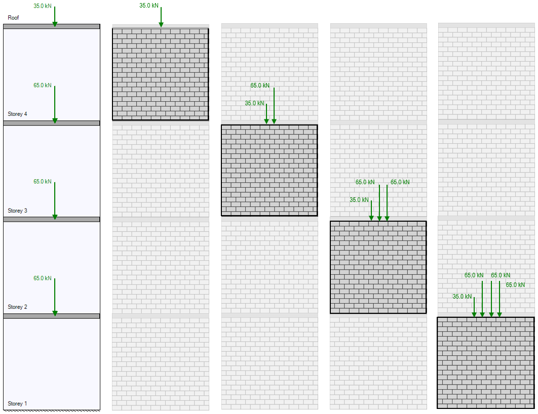 If the live load from the roof is 35kN and each floor has a live load of 65kN, the top shear wall element will only need to resist the 35kN roof load. Looking at the bottom shear wall element at the first floor, not only is the roof load applied and resisted, but there is also a 65kN load from the top of floor 3, a 65kN load from the top of floor 2, plus the 65kN live load being applied directly to the top of the first floor shear wall element. The total axial load applied as a function of height is shown below:
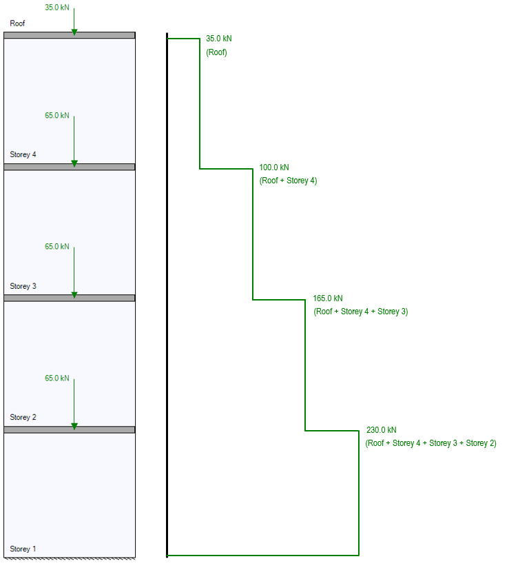
Recall that this example is dealing with applied, unfactored, live loads. Combinations are dealt with in the individual shear wall element stage and self-weight is technically applied continuously along the height of the structure.
Factored axial load can have a stiffening effect on shear wall deflection from earthquake loads, but since multi-storey shear walls are statically determinate, axial load distribution will have no effect on bending moment and shear. More information on this aspect can be found in the shear wall deflection section, found by clicking here.
Vertical Load Eccentricities
Vertical loads are applied at the middle of the wall with no eccentricity by default. In the case of a uniformly distributed load landing on a shear wall section from the floor slab resting upon it, the resultant force is balanced and also applied at the middle of the wall, resulting in zero net eccentricity.
In the case where a vertical load rests at a different physical location along the shear wall or there are different tributary areas the floor resting upon the wall, it may be necessary to apply the axial load at an eccentricity. This can be done by inputting the eccentricity at the bottom of the vertical load column for that type.
For instructions regarding how to apply a vertical load at an eccentricity, click here to visit the Multi-Storey Shear Wall Design Steps page.
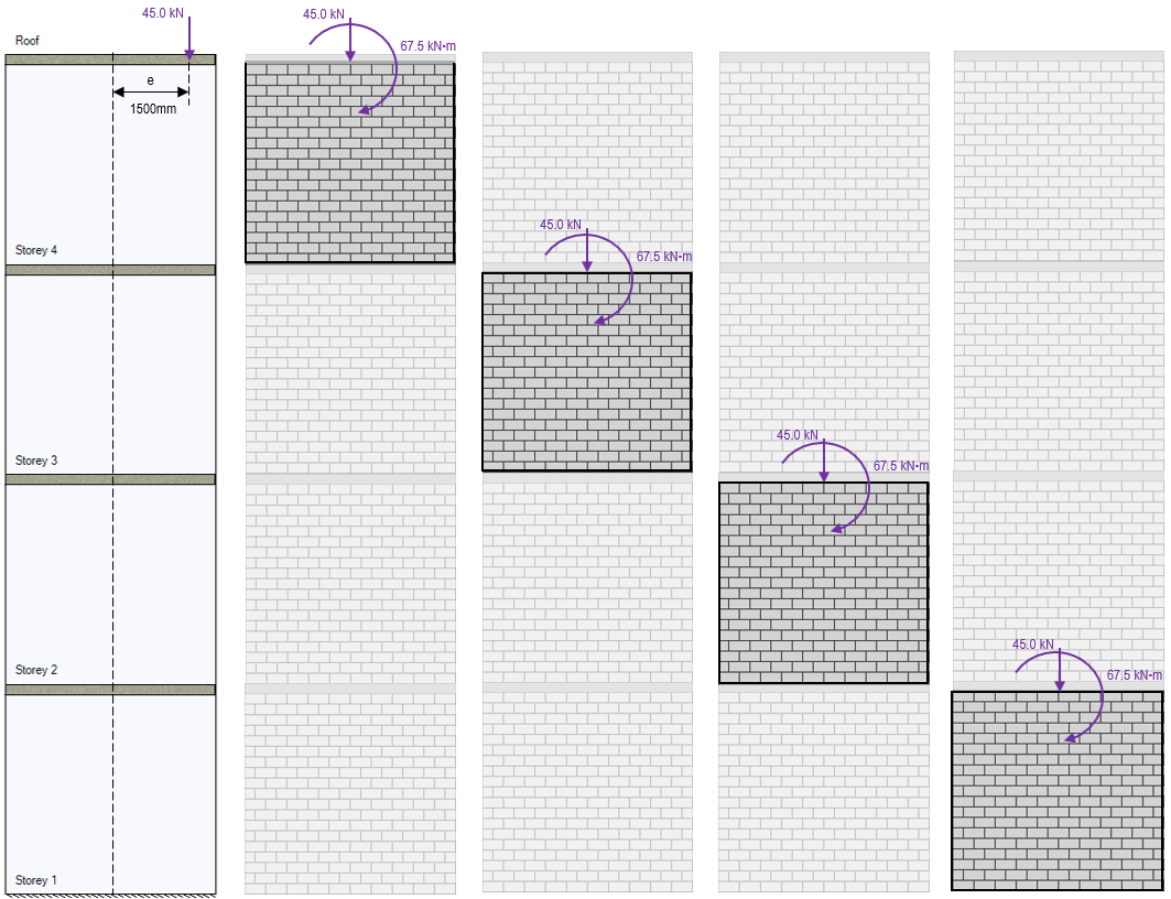
In the example figure above, the snow load used in the multi-storey load distribution example has been applied at a distance of 1500mm from the middle of the wall. The result is a snow type applied moment that is experienced by each shear wall element beneath the location where the vertical load has been applied.
Note: Within the design for each shear wall element, there is no further acknowledgment of the axial load eccentricity beyond the presence of the applied moment. The calculation and application of this moment is the software’s way of taking the eccentricity into account.
Distributing Lateral Loads
Similar to axial loads, all lateral loads are resisted by any shear wall element beneath the location where the load has been applied… with one important distinction. Since axial loads have been applied at the same horizontal position along the height of the wall, there have been no resulting moments due to axial load eccentricities. This will be covered further down in the “Resulting bending Moment” section. The shear forces distributed to each element are outlined in the next paragraphs.
Resulting Shear Force
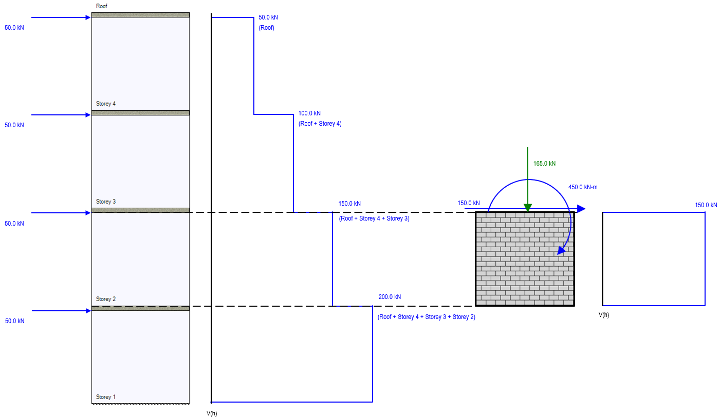
All shear wall elements beneath the location where a lateral load is applied will resist that force. For example, a lateral wind load of 50kN applied at the top of a 4 storey shear wall is resisted by all four of the individual shear wall elements by being applied to each element design module.
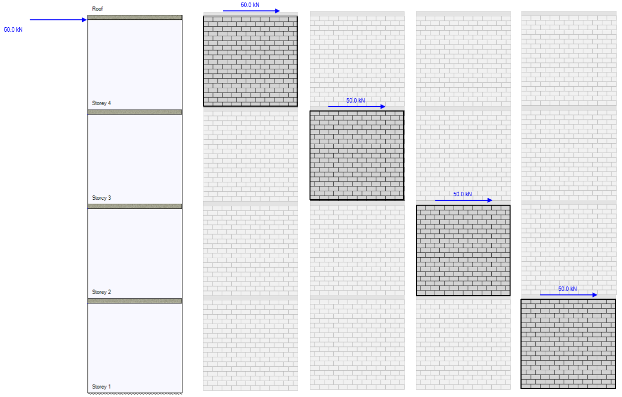
The lateral wind load shown in the figure above is resisted by each shear wall beneath it. This principle can be extended to loads applied between floor locations, shown below.
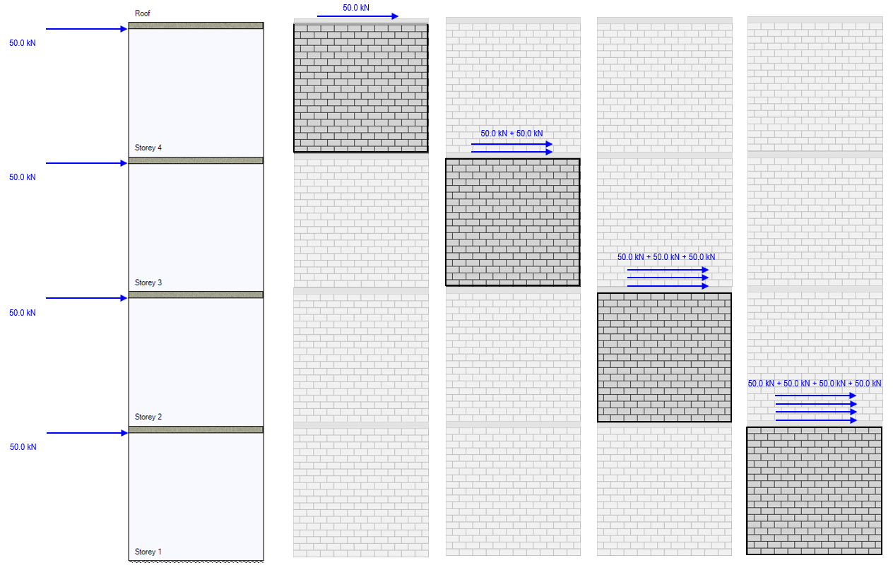
If each lateral wind load is 50kN, the total shear force experienced by the bottom storey shear wall will be 200kN since it is beneath all four applied loads.
Note: Recall that unfactored lateral loads of the same load type are not combined to reduce the number of loads shown for each shear wall element design. This is intentional to allow the user to examine any one component and trace back it’s origin, useful for checking software results by hand.
Resulting Bending Moment
When is comes to bending moment (also referred to as overturning moment for multi-storey shear wall designs), the process of load distribution is slightly more complicated as the moment magnitude is a product of both the lateral point load magnitude and the difference in height between where it is applied and where it is being distributed to.
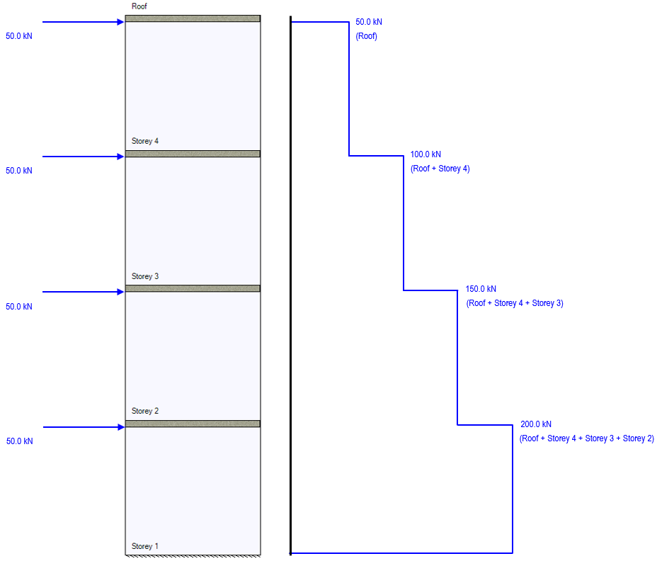
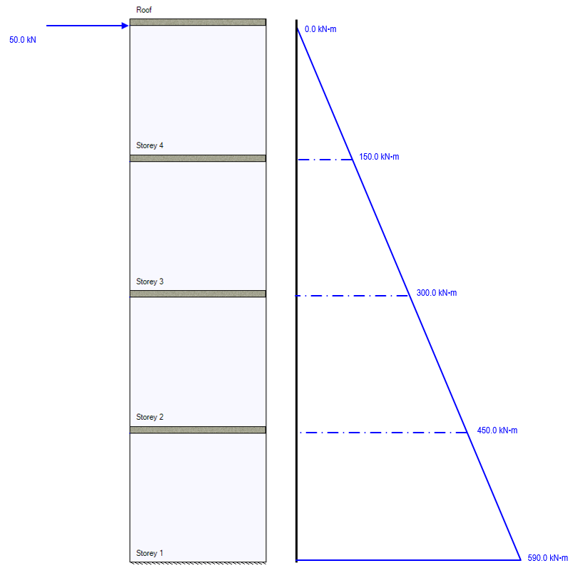
Starting with a simple example, consider the scenario where only one lateral wind load is applied at the top of the structure, coming in where the roof meets the top of the uppermost shear wall element. As per the section above, the lateral load is simply experienced by any element beneath where it is applied. When calculating the overturning moment, the amount experienced at the top of any given storey within the structure is equal to the force times the position difference between where it is applied (the roof) and where it is being distributed to (top of storey being considered).
The resulting moment envelope from that single lateral load is shown below:
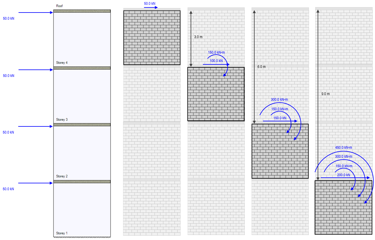
In order to ensure that each shear wall element is designed for the correct load based on what has been applied to the multi-storey assemblage, an applied moment must be added to account for the positional difference between where a load is applied and where it is being considered.
Note: While each storey is 3m in height, the moment at the base is not 600 kN*m because the loads are applied at the top of each wall (rather than at the floor surface level) so the height different between the base of the wall and the top where it is applied is 12m minus the 200mm default slab thickness.
Ratcheting things up to include a 50kN lateral load coming in at each floor, the resulting overturning moments are shown in the figure below:
The resulting bending moment diagram expressed along the height of the assemblage is shown with the individual moment contributions from each load shown in faded blue within:
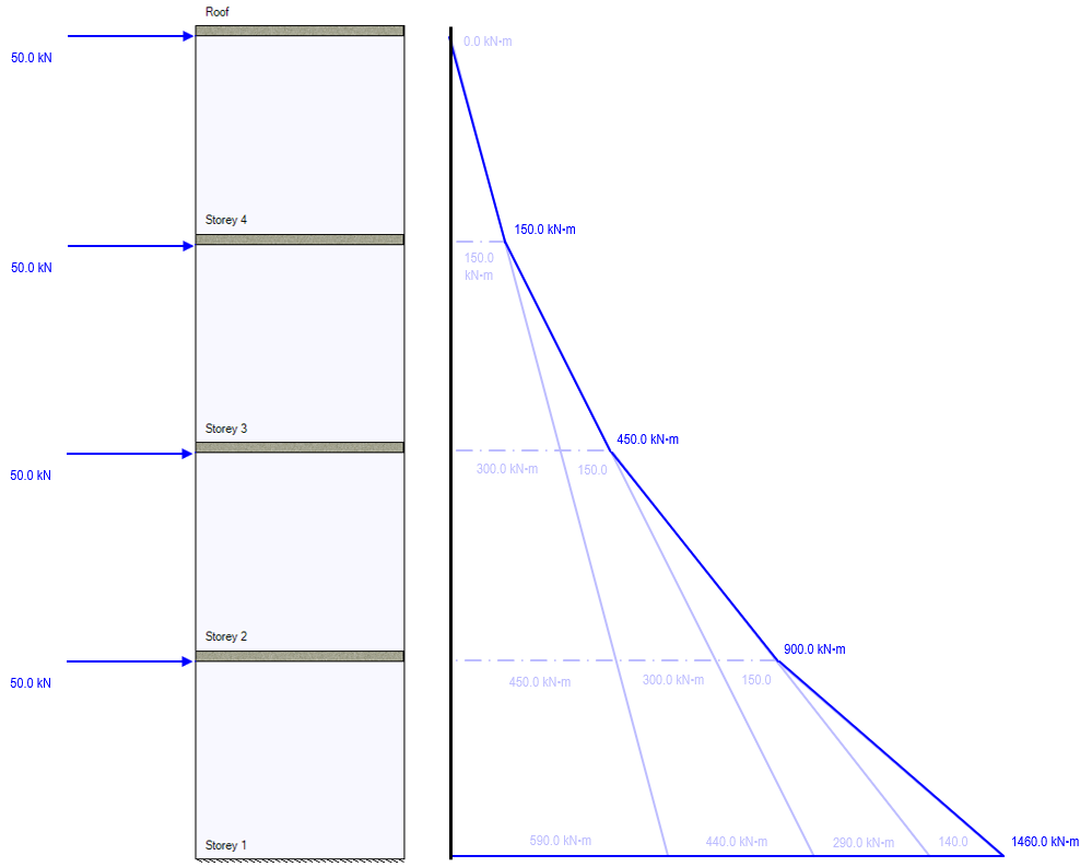
Similar to the single-load example, the height difference between the top of the storey 1 shear wall and the level at grade is 3m minus the default 200mm slab thickness.
All moment, deflection, and shear design performed by MASS on each element is a result of how the loads applied to a multi-storey module are distributed. It is important to understand that the software does not take moment or shear values from the multi-storey and use them for design. Rather, the way this is handled is by applying point loads and applied moments to that the same values end up being designed for at the element level.
Example Storey Distribution
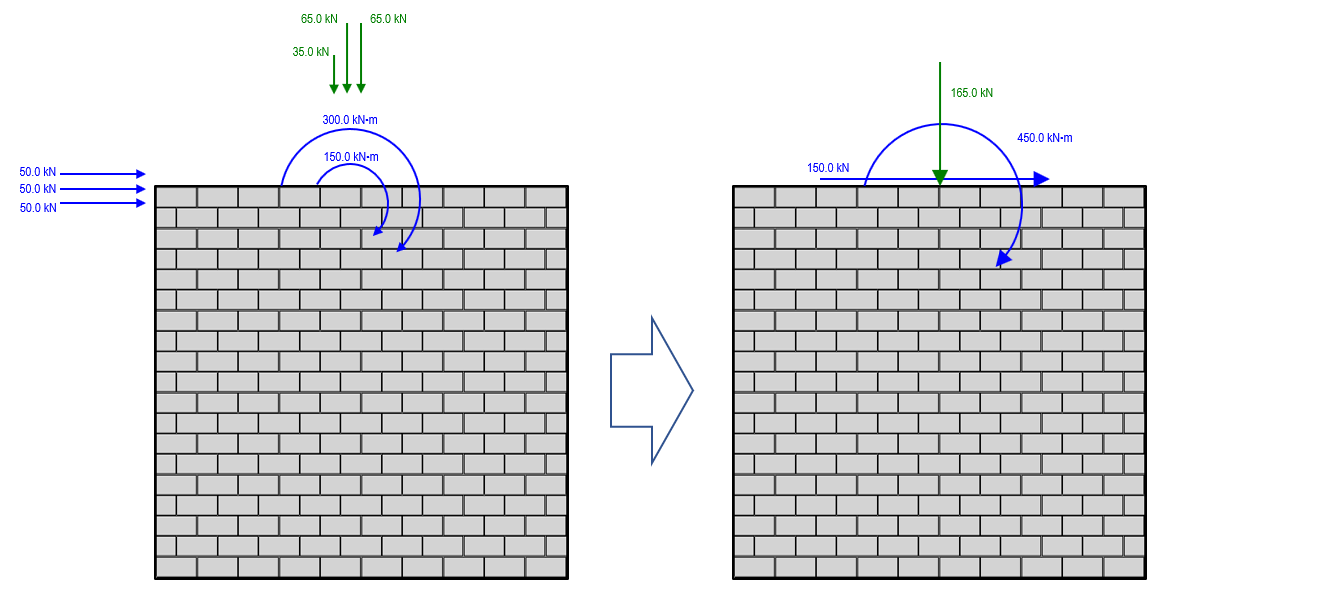
Consider a combination of the examples above with axial live loads and lateral wind loads applied at the roof as well as the base of each storey. If looking specifically at the design of Storey 2, the only relevant loads impacting that design are applied at the top of the wall under consideration and above. Distributing these to the top of storey 2, the result is the following:
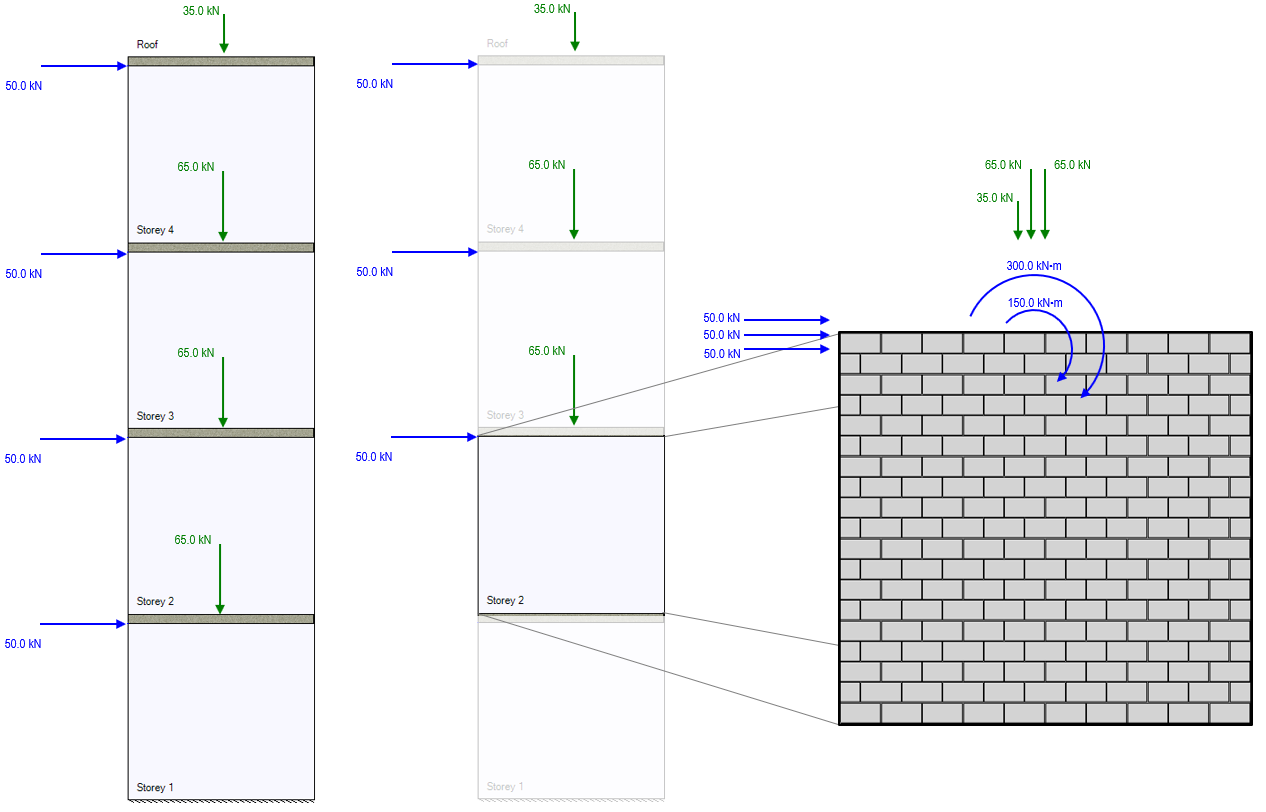
There are three axial point loads which will be resisted by storey 2:
- 35kN live load applied at the top of storey 4.
- 65kN live load applied at the top of storey 3.
- 65kN live load applied at the top of storey 2.
Note that the live load applied at the top of storey 1 is not included in this example because it has no impact on the shear force or bending moment experienced by an element (storey 2) above it.
There are three lateral point loads which will be resisted by storey 2:
- 50kN wind load applied at the top of storey 4.
- 50kN wind load applied at the top of storey 3.
- 50kN wind load applied at the top of storey 2.
Note that the lateral wind load applied at the top of storey 1 is not included as it is applied beneath the section under consideration.
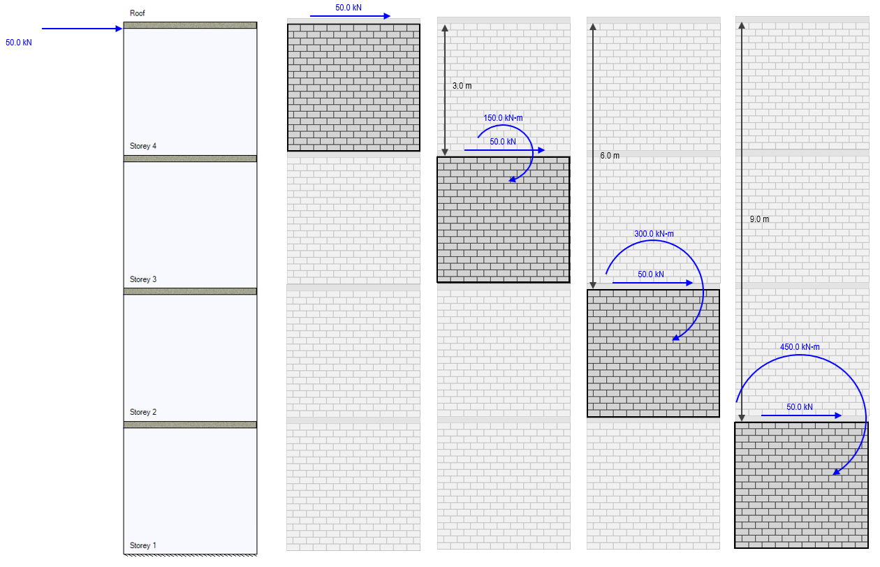
There are two overturning moments from lateral line loads resisted by storey 2:
- 300kN*m wind moment from the 50kN wind load applied 6m above at the top of storey 4.
- 150kN*m wind moment from the 50kN wind load applied 3m above at the top of storey 3.
Note that there is no overturning moment resulting from the lateral wind load applied at the top of storey 2 because the lateral load is applied at the same location where it is being resisted. Since the moment arm has a length of zero, when multiplied by the lateral load, the resulting moment is also zero.
Based on only the loads shown in this example, these 8 loads will be applied to the top of the Storey 2 shear wall element for design. To check and confirm that these load distributions will accurately reflect the multi-storey design, the loads can be simplified to get one axial load, one lateral load, and one overturning moment value to check with the shear force and bending moment diagrams shown earlier in this page. These are not combined within MASS.
Checking this axial load with the diagram used for the full multi-storey shear wall, the total axial load of 165kN applied to the Storey 2 element matches that for the same location in the multi-storey axial load diagram.
Comparing the shear force along the height of Storey 2 to that of the individual element with distributed loads, the same unfactored 150kN along the entire height is used.
For overturning moment, the bending moment diagram for the individual element design of Storey 2 exactly matches that of the Storey 2 portion within the full multi-storey bending moment diagram.
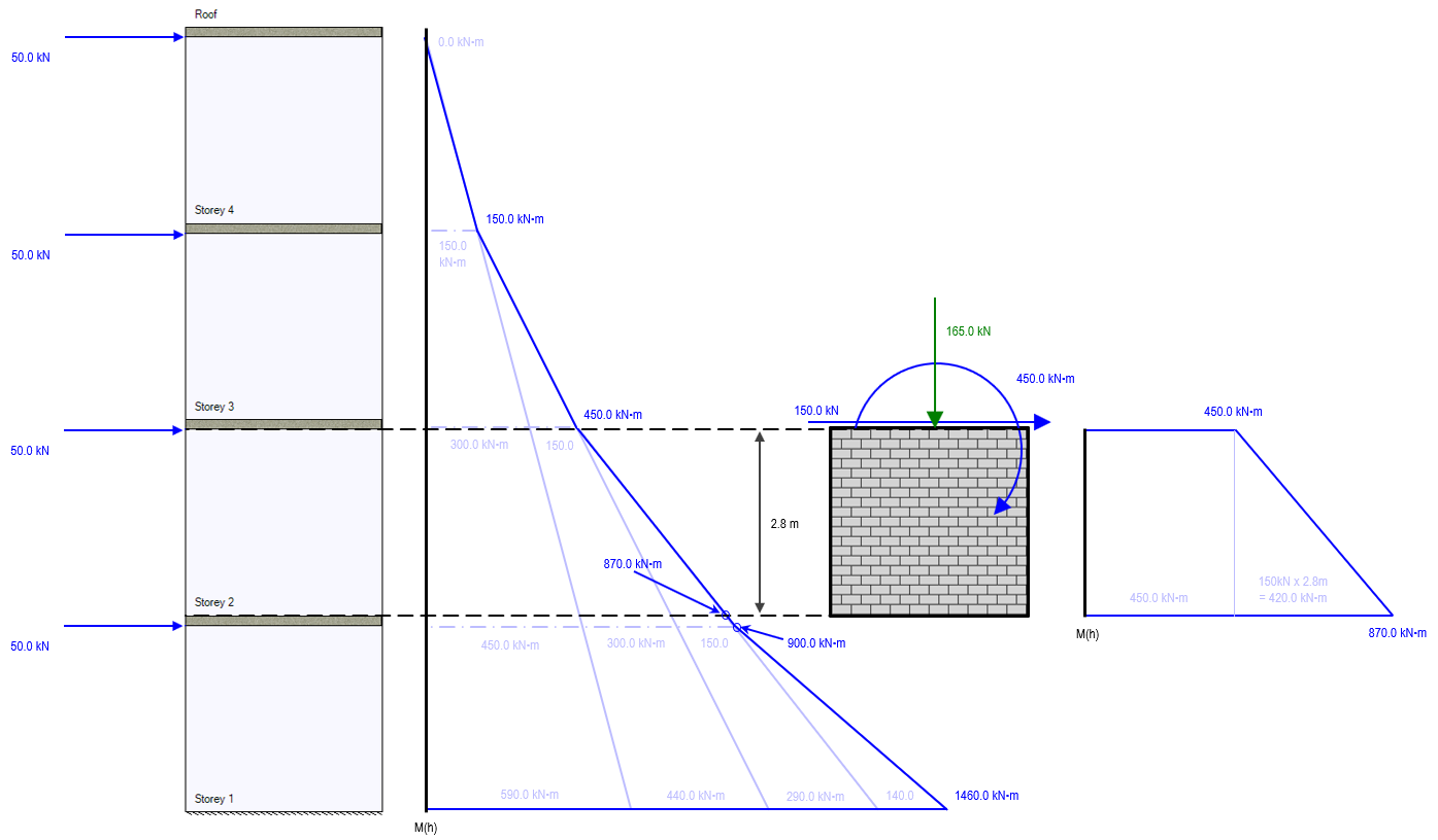
The moment at the base of Storey 2 has 2 components that are determined. The first is from the applied moment at the top of that element, equal to 450kN*m in this case. This moment is constant along the entire height and therefore also 450kN*m at the base of the wall. The second component of the moment at the base is the additional bending moment resulting from the lateral load applied at the top of Storey 2, 2.8m above the base. This component is handled by MASS within the design of Storey 2
Note in the moment diagram that the base of storey 2 is one floor slab thickness (200mm or 0.2m) above the top of Storey 1, which is why there is a difference of 30kN*m in moment between those locations (150kN x 0.2m = 30kN*m).
Continue Reading: Multi-Storey Shear Wall Deflection (Overview and Calculation Example)
Was this post helpful?