

Shearline Design Strategy
Shearline Design Strategy
Contents
This section provides users with information on how MASS™ coordinates the design of several piers to obtain an overall shearline design.
Shearline Design Stages
The shearline design process can be broken down into three distinct stages:
- Load Distribution
- Critical Pier Design
- Group Design
These steps are performed one after the other and can be done several times for a single shearline design. For information on how MASS™ cycles from one stage to the next, refer to the Design Process Explained section.
Note: Only the Piers selected for design are considered when designing a shearline.
Load Distribution
Loads need to be applied to all piers within a shearline before a design can be performed. MASS™ starts by distributing all lateral loads, applied moments and vertical loads based on the smallest, weakest masonry unit with the least reinforcement, as seen below in Figure 75: Initial load distribution properties based on default masonry unit and reinforcement selections, highlighted in blue.
 Figure 75: Initial load distribution properties based on default masonry unit and reinforcement selections
Whenever there is a change in masonry properties between designs loops, the loads are redistributed based on the updated properties.
A complete description on how loads applied to a shearline are distributed to individual piers can be found in the Pier Generation page.
Critical Pier Design
Initially, each pier is designed as a shear wall based on the loads which are distributed to it, unaffected by all other pier design results. This is referred to as the Critical Pier Design stage. The purpose of the critical pier design stage is to determine the governing assemblage configuration for each group. Pier tabs perform moment and shear design based on the masonry and reinforcement selections made under the materials tab from the shearline assemblage design step. All of the pier designs are run at once and results are located within the Pier Design Summary tab in the shearline module.
Group Design
The group design stage is very similar to the critical pier design stage where each pier is designed based on the assemblage configuration of the critical pier design for their similar group.
The properties used for the group design stage are based on the critical pier design results, in which there is a masonry unit size and strength saved for each pier. The highest strength of the largest size unit is used for all of the piers within each group. By using multiple groups, users can complete a shearline design that makes use of multiple masonry units with different sizes and strengths. For more information regarding groups and how to create and manage multiple grouped properties, refer to the Assemblage Configuration section.
Design Process Explained
Shearline uses an iterative, recursive design process to determine which design can be used for each pier within a shearline. The iterative component is borrowed from the shear wall design strategy where all possible configurations are attempted for each pier until one passes for moment and shear, based on the applied loads. The design process is recursive because it is based on a cycle where loads are repeatedly distributed based on the previous design results until there is convergence between the current and previous design results. The process can be seen below in Figure 76: Design process workflow as a flow chart with the transitions between components numbered as Steps from 1 to 6.
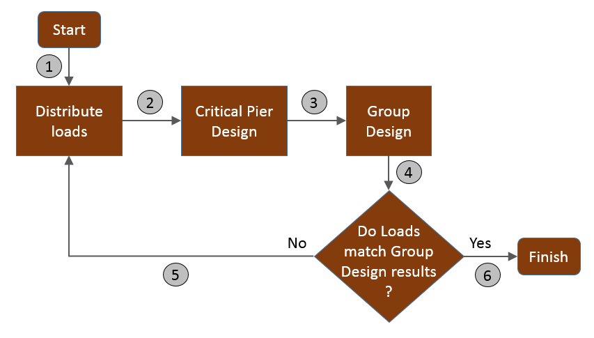 Figure 76: Design process workflow
Shearline Design Process Steps (as seen above in Figure 76: Design process workflow):
- The beginning of the design process. Loads are initially distributed based on the smallest, weakest masonry unit for all piers based on all available user selections. Unfactored loads are applied to all piers.
- Piers are designed based on previous load distribution using all user specified masonry unit size and strength options.
- Of all of the critical pier results, the highest strength unit with the largest block thickness is selected for Group Design. All piers are designed using only the specified group size and strength.
- Does the masonry unit and strength selected for Group Design match the size and strength used for the most recent load distribution? If none of the Piers required a design using a larger or stronger unit than the lowest available in the materials tab, the design process will be complete after only one cycle.
- If the group properties have since changed, the loading on each Pier will need to be updated to reflect the current design results. All loads will be redistributed using the selected group properties. Continue to step 2 (above).
- If the group properties used in the most recently performed Group Design match those used for the most recent loads distribution, the shearline design process is complete.
These steps can be applied to any shearline assemblage. Most shearlines with only 1 group will require only 2 cycles but shearlines with multiple groups may take longer to converge. If a shearline design is taking a very long time to converge, users can speed up the process by reducing the number of available masonry unit sizes and strengths available, reducing the number of iterations needed.
Design example
The following example as seen in Figure 77: Shearline design example using a simple shearline where several Piers are designed. In this example, all of the piers have been selected for design to resist a lateral seismic point load of 300kN.
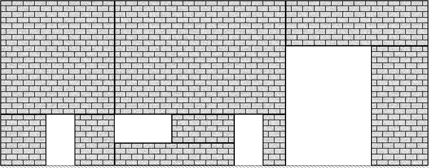 Figure 77: Shearline design example
By default, all Piers within a shearline use the same masonry properties which are assigned to Group 1. The first stage is to distribute the loads to each pier based on the initial default masonry properties. Using the default selections, this would be a 100mm (nominal dimension), 15MPa unit for the entire wall. For more information on how the loads are distributed to each pier, refer to the Pier Generation page.
Once the load distribution is completed, the Critical Pier Design is performed where each pier is designed for axial load, moment and shear. The results for this example are shown below in Figure 5: Masonry unit size and strength for governing Pier used for Group design of every Pier.
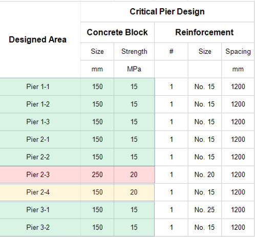
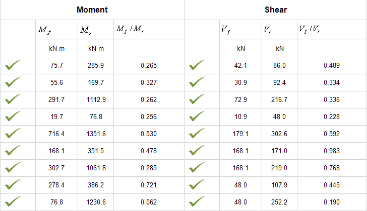
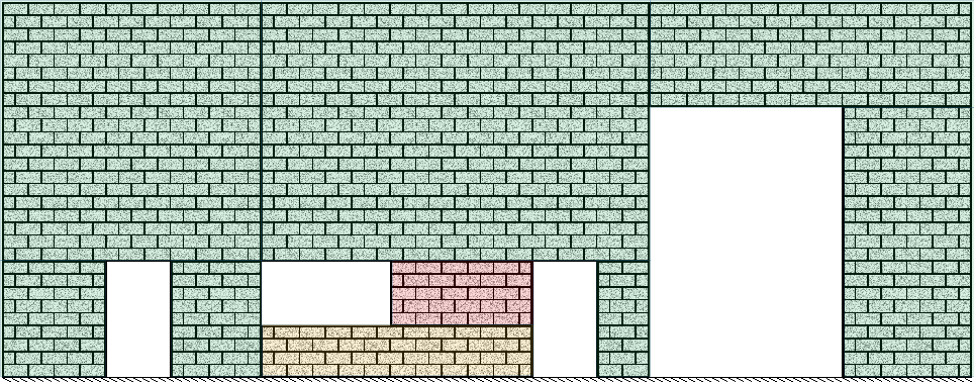 Figure 4: Block sizes and strengths from Critical Pier Design results shown on shearline
In this design, the governing section is Pier 2-3, which requires a 20MPa, 250mm unit. The second largest design is Pier 2-4 which requires at least a 20MPa, 150mm unit. All of the other Piers pass using a 15MPa, 150mm unit which happens to be the smallest, weakest block that allows reinforcement.
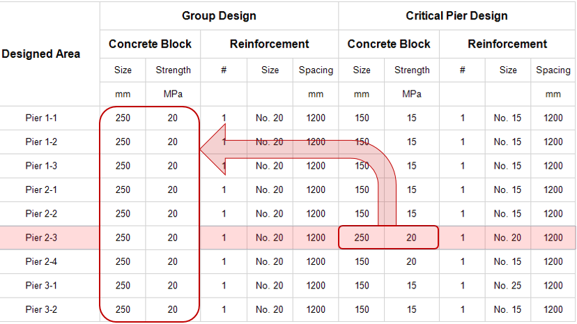 Figure 5: Masonry unit size and strength for governing Pier used for Group design of every Pier
The governing critical pier design is then used to select the properties used in the Group Design, where all piers are designed again for both moment and shear. After the Group Design is completed, MASS™ compares the masonry unit used for the Group Design (250mm, 20MPa) to the unit used for the load distribution (100mm 15MPa). The loads are then redistributed based on the 250mm, 20MPa unit and the Critical Pier Design is performed, followed by the Group Design. After performing the second Group Design, the masonry unit selected is still a 250mm, 20Mpa block. This matched the unit used for the most recently performed load distribution so the design process is complete and the results can be displayed.
Continue Reading: Multi-Storey Shear Walls