

Latest Software Blog Posts
Change Notification: Axial Load Limit for Conventional Construction Walls
The axial load limit for a Conventional Construction shear wall with a seismic hazard exceeding 0.35, currently in MASS, complicates the design of these walls.
In cases where a bug or other issue is found in the MASS software, announcements are posted on the software’s known bugs page, as well as on this page here. It is always encouraged that suspected bugs are submitted by engineers through technical support.
Disclaimer: This post is exclusively intended to provide insight into the approach taken by the MASS design software in implementing a comprehensive analysis for Conventional Construction shear walls. It is up to the professional discretion of the designer to input an appropriate layout, boundary and loading conditions, interpret the results, and determine how they should be incorporated into their designs. As per the end user license agreement (and also recommended within PEO’s guidelines for using engineering software), a tool cannot be considered competent and reliance on a tool does not relieve the user of responsibility.
Summary
MASS evaluates the axial load applied to a Conventional Construction wall with a seismic hazard index exceeding 0.35, ensuring it remains less than the allowable limit of 0.1f’m. In MASS v4.2, users now have the option to conduct a comprehensive analysis. This analytical enhancement is designed to effectively address scenarios where the axial load surpasses 0.1f’m, building upon the insights outlined in the research paper authored by Bennett Banting, titled “A proposed method to address the limitation on Axial Load for Conventional Construction Shear Walls in the 2014 CSA S304.”
Within MASS, determining the appropriate comprehensive analysis method depends on whether the wall in question is squat or not. Users still retain the option to adhere to the axial load limit of 0.1f’m if they choose not to employ the comprehensive analysis feature. It is important to note that bypassing the comprehensive analysis will significantly reduce the allowable axial load for Conventional Construction shear walls, potentially making the design process more challenging.
Background Information
The 2014 edition of CSA S304 underwent several notable revisions, with one of the most significant being the inclusion of Clause 16 Special provisions for seismic design. This clause serves as a pivotal consolidation of seismic-related provisions and an expansion of seismic design requirements. One standout addition within these new provisions pertains to the seismic force resisting system (SFRS) Conventional Construction Shear Walls (Rd = 1.5, Ro = 1.5), where explicit design criteria were established.
Of particular focus, and central to our current article, is the introduction of an axial load limit outlined in Clause 16.5.3. This limit is applicable to walls where the seismic hazard index, IEFaSa(0.2), equals or exceeds 0.35. As explained, the axial load must not surpass the threshold of 0.1f’m. It’s crucial to emphasize that this restriction leads to a sudden and marked decrease in wall capacity when compared to Conventional Construction shear walls with a seismic hazard index of 0.34 or lower.
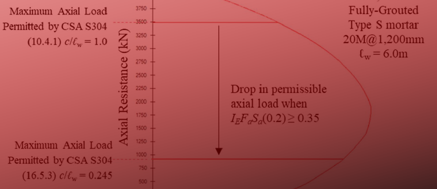
When comparing the neutral axis depth to length of wall ratio (c/lw), a dramatic difference emerges between walls with a seismic hazard index of 0.34 or lower and those of 0.35 or higher. When the seismic hazard index is below 0.35, CSA S304 (10.4.1) limits the maximum axial load to the following:
![]()
If dealing with a fully-grouted section and comparing to an effective compression block equation for masonry design under compressive forces, a neutral axis depth to length of wall ratio of 1.0 can be derived (c/lw = 1.0) as follows:
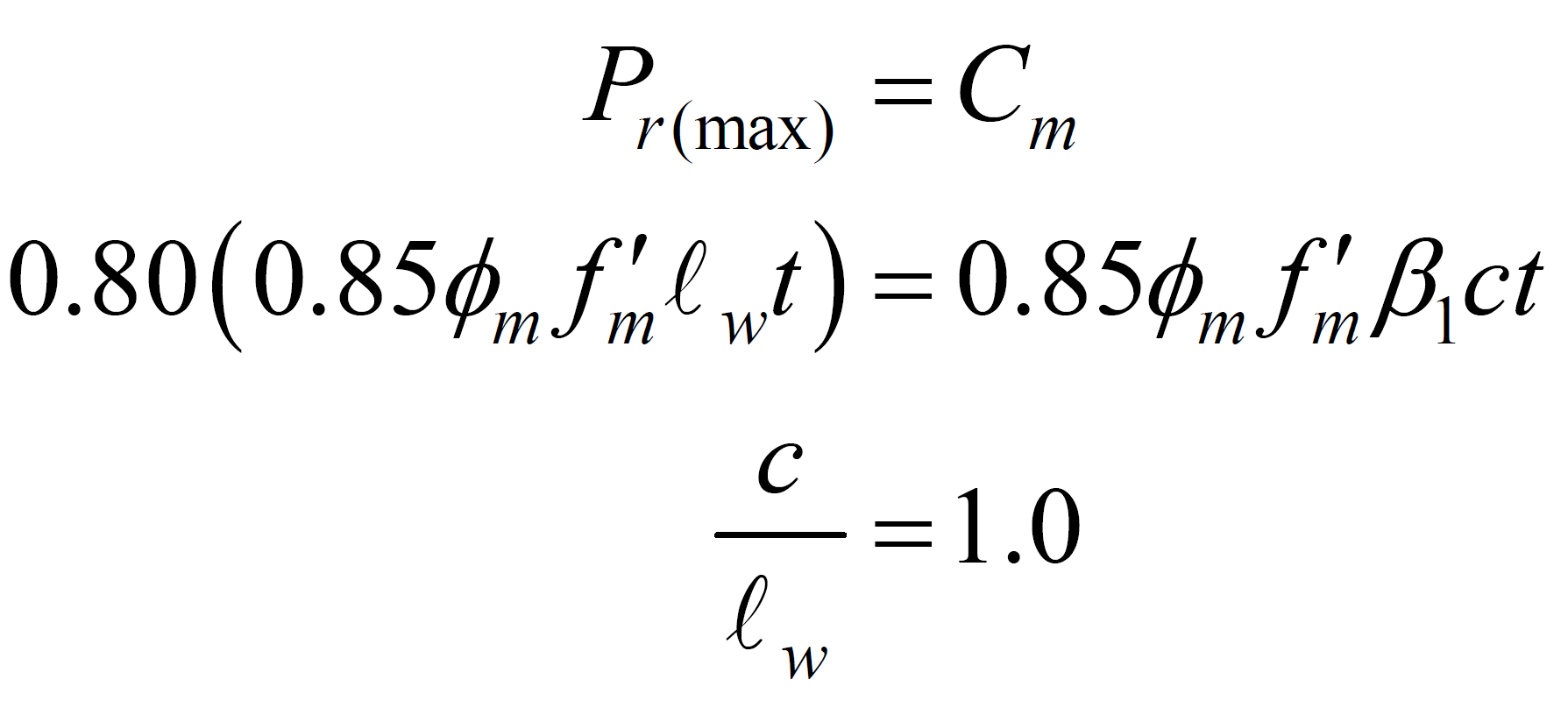
Applying the same process to shear walls with seismic hazard index of 0.35 or higher, where CSA S304 (16.5.3) limits the axial load to Pf ≤ 0.1f’m, c/lw ratio of less than 0.245 is estimated (the actual ratio would change with the masonry strength and reinforcement ratio in the wall). Figure 1 below, provides a good depiction of these limits by using an interaction diagram and the neutral axis depth to length of wall (c/lw) ratios.
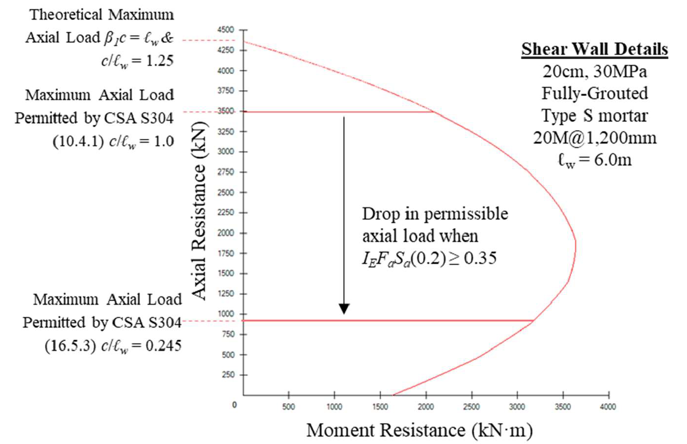
Figure 1: Interaction Diagram and Axial Load Limits of a Conventional Construction Shear Wall
This comparison brings to light the seemingly arbitrary nature of the axial load limitation imposed on walls with a seismic hazard index exceeding 0.35. Currently, there is no theoretical foundation for assigning a design level axial load based on a singular percentage of the specified masonry strength. It is recognized that c/lw ratios offer invaluable insights into the theoretical ductility capacity of a shear wall undergoing plastic hinging. However, the level of ductility capacity is also associated to a series of parameters related to the inelastic rotations within the wall, wall aspect ratio, and ultimate strains in the masonry and steel reinforcement.
Although CSA S304 (16.5) does not provide any explicit alternative analysis approach to overcome this strict reduction to axial load levels, Clause 16.5.1 permits deviation from the requirements in Clause 16.5 if “a more comprehensive analysis” is performed.
A More Comprehensive Method
The proposed comprehensive analysis described in this article makes an important distinction between squat and non-squat shear walls. Non-squat walls exhibit different behavior and inelastic energy dissipation methods in comparison to squat walls. In the context of non-squat walls, the mechanism of inelastic seismic energy dissipation is achieved through flexural plastic hinging. Conversely, in squat walls, the process of inelastic energy dissipation is governed by a shear-dominated response within the wall. Consequently, it becomes evident that the formulation of two distinct comprehensive methods is necessary, each tailored to address the unique characteristics of squat and non-squat walls respectively.
Squat Walls
Squat walls are not expected to undergo an inelastic flexural response to lateral loading. Rather, to ensure that a Conventional Construction squat wall can meet the inelastic demand for Rd = 1.5, the process for designing Rd = 2.0 Moderately Ductile squat shear walls, in accordance with Clause 16.7 in CSA S304, can be adapted to support a more comprehensive analysis. Only provisions related to axial load effects in the design of Moderately Ductile squat shear walls per Clause 16.7 in CSA S304 will be considered and conservatively applied to Conventional Construction squat walls. The design requirements that form a more comprehensive analysis for Conventional Construction squat shear walls are summarized in Table 1 below:
Table 1: Design Requirements for Conventional Construction Squat Shear Walls
|
Proposed Design Requirement |
Commentary |
| Squat shear walls having a height-to-length ratio (hw/lw) less than 1 shall be designed to the following: | These requirements are in addition to all those already applicable to Conventional Construction shear walls. The following can be used in lieu of the axial load limit per Clause 16.5.3 in CSA S304. |
| a. The unsupported height of the wall shall be such that the height-to-thickness ratio (hw/(t+10)), of the wall in the compression zone is less than 20 (Clause 16.7.4, CSA S304) | Since there is no rational way to alter this limit for the reduced ductility demands of Rd = 1.5 versus 2.0, it is suggested that the Moderately Ductile squat shear wall limit is used directly. |
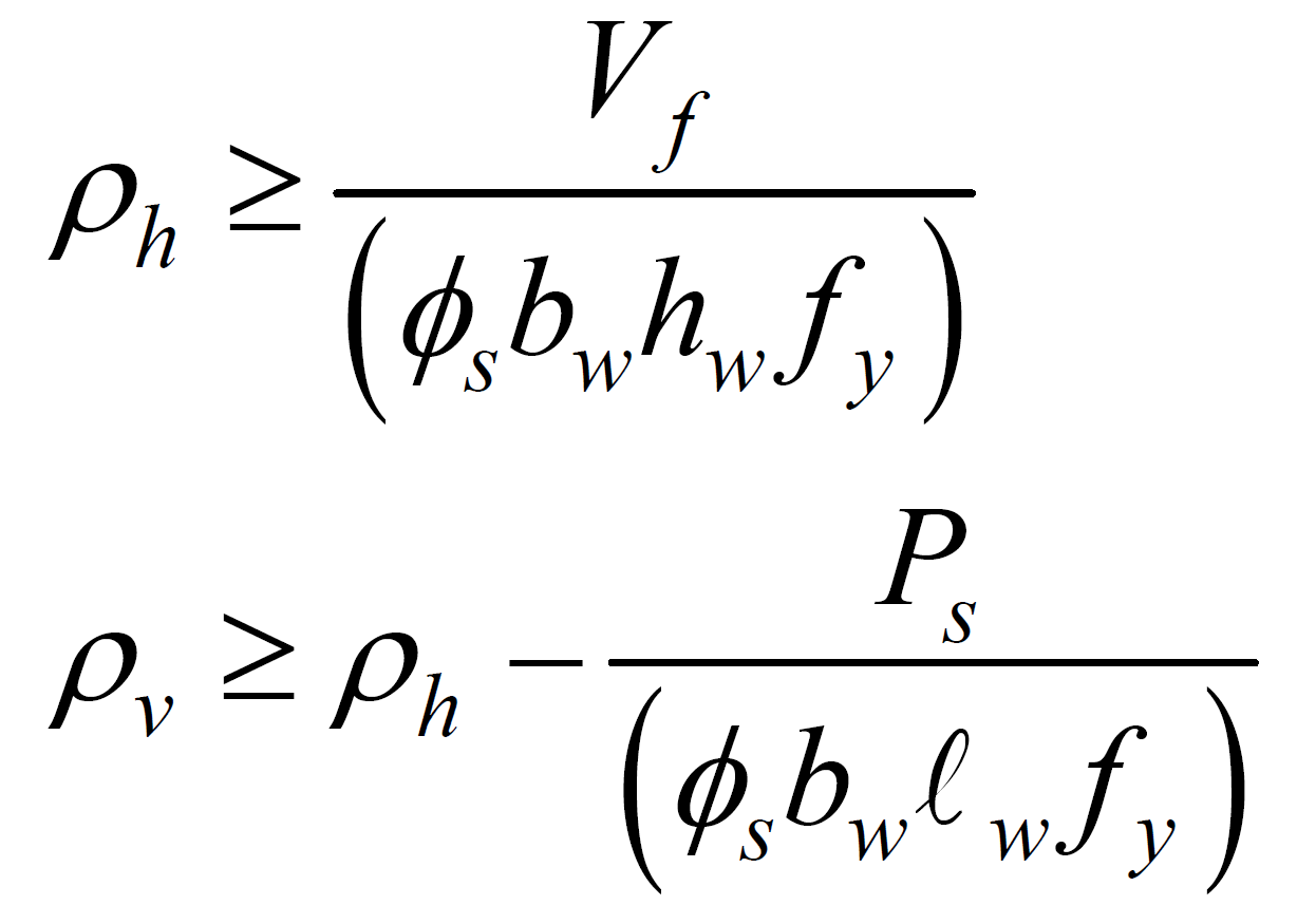
| b. Horizontal and vertical reinforcement ratios shall not be less than that determined using the following equations (CSA 16.7.5, CSA S304):
|
Reinforcement requirements that relate to axial load are included here. This is done to ensure that compression struts in the cracked cross-section are properly accounted for within the equilibrium of forces in the reinforcement. These requirements are designed to ensure Rd = 2.0 behaviour and are conservatively also adopted here. |
Non-Squat Walls
Non-squat shear walls allow for the direct evaluation of the c/lw ratio to ensure adequate inelastic flexural capacity to facilitate inelastic rotational demands placed on the wall. However, CSA S304 does not offer a singular c/lw ratio limit that could be adapted for Conventional Construction shear walls.
Clause 16.8.8.4 in CSA S304 provides an equation based on mechanics to directly calculate the limiting c/lw ratio based on the inelastic rotational demand and inelastic rotational capacity within the plastic hinge region of a shear wall for the design of Moderately Ductile shear walls. Since Rd and Ro can be directly entered as variables in the equation, its application is possible for the Conventional Construction category and serves as the basis for the proposed design provisions meant to meet the criteria as a more comprehensive analysis given in Table 2 below:
Table 2: Design Requirements for Conventional Construction Non-Squat Shear Walls
|
Proposed Design Requirement |
Commentary |
| Shear walls having a height-to-length ratio (hw/lw) greater than or equal to 1 shall be designed to the following: | These requirements are in addition to all those already applicable to Conventional Construction shear walls. The following can be used in lieu of the axial load limit per Clause 16.5.3 in CSA S304. |
| a. The unsupported height of the wall in the plastic hinge shall be such that the height-to-thickness ratio (hw/(t+10)), of the wall in the compression zone is less than 20. Exclusions are also permitted for walls with thicker sections at the end, neutral axis depths of a certain limit and walls with flanges per Clause 16.8.3.2-16.8.3.4 in CSA S304 but are not repeated here for brevity. | Since there is no rational way to alter this limit for the reduced ductility demands of Rd = 1.5 versus 2.0, it is suggested that the Moderately Ductile squat shear wall limits are used directly. |
| b. The area of the wall which contains the plastic hinge shall be fully-grouted. | Moderately Ductile shear walls are permitted to have a plastic hinge region that is partially grouted per Clause 16.8.5.2 in CSA S304. However, this is limited only to walls with a seismic hazard less than 0.35 and axial stress less than 0.1f’m. Therefore, it can be reasoned that this same conservatism should also be applied to walls of Conventional Construction with high axial loads and high seismic hazard. This is likely an overconservative approach. |
| c. The extent of the plastic hinge region, hp, above the base of the wall shall be taken as lw. | To achieve Rd = 1.5 through flexural yielding of reinforcement the theoretical height over which this yielding occurs must be assumed. This limit only applies to detailing requirements a. and b.
Other detailing requirements for the plastic hinge (i.e., lap splices, bar spacing, ԑmu etc.) are intended to facilitate a plastic hinge that can develop Rd = 2.0. Existing detailing requirements for Conventional Construction walls Rd = 1.5 should still apply since there is no change ductility demand/capacity. i.e. “The plastic hinge region is an already existing feature in flexurally-governed Conventional Construction shear walls that can achieve Rd = 1.5 using the provisions of Clause 16.4 and 16.5 of CSA S304.” |
| d. The inelastic rotational demands and maximum axial load for a Conventional Construction non-squat shear wall are deemed to be satisfied by the following limit per Clause 16.8.8.4 in CSA S304:
Where: c = the neutral axis depth for the factored earthquake load case under consideration lw = the length of the wall being designed ԑmu = 0.003 Ar = the aspect ratio of the wall being design (hw/lw) Δf1 = the lateral elastic deflection at the top of the shear wall under factored loads γw = the wall overstrength factor equal to the ratio of load corresponding to the nominal moment resistance (determined using Φs = Φm = 1.0) to the factored load on the wall. It need not be taken as less than 1.3 and shall not be taken greater than RdRo = 2.25. ԑy = 0.002
|
This equation can be derived by assuming that the plastic hinge region at the base of the wall is conservatively taken as equal to lw for determining inelastic rotation demands per Clause 16.8.8.2 in CSA S304 and as lw/2 when determining inelastic rational capacity as per Clause 16.8.8.3 in CSA S304.
In order to apply the same principles to Conventional Construction shear walls the following is assumed: 1. A plastic hinge region of a Conventional Construction shear wall is not subject to detailing restrictions of Moderately Ductile shear walls as explained previously. The “hinge” is simple a recognition of where flexural yielding of reinforcement can take place. Walls are still expected to meet Rd = 1.5 requirements. 2. Having a Rd = 1.5 designation recognizes very limited ductility. There are already height limits in the NBCC for regions of moderate to high seismic risk. It is widely recognized that the required inelastic capacity in Rd = 1.5 shear walls can be facilitated through a combination of flexural yielding of reinforcement, cracking masonry, shear deformations, and system overstrength. 3. The use of Clause 16.8.8.4 in CSA S304 explicitly accounts for scenarios when seismic demands are high by requiring a direct calculation of Δf1 without the need for arbitrary limits based on hazard. |
Impact Analysis of the Proposed Design Requirements
Design of Conventional Construction Squat Shear Walls
The limit of 0.1f’m for Conventional Construction shear walls was more restrictive than the limits in place for Moderately Ductile squat shear walls. Simply adopting the provisions for Moderately Ductile squat shear walls ensures that walls of Conventional Construction have sufficient inelastic capacity when axial stresses exceed 0.1f’m. The height-to-thickness ratio limit and the newly introduced minimum reinforcement requirements are not anticipated to create significant disruptions in cases where axial loads are already high in squat walls.
Design of Conventional Construction Non-Squat Shear Walls
Moderately Ductile shear walls do not limit the overstrength value, γw, however a minimum inelastic rotational demand of 0.003 is required to be met as per Clause 16.8.8.2 in CSA S304. Minimum demands are only employed for Moderately Ductile and Ductile shear wall systems and there is no rational means to provide a similar limit to walls of Conventional Construction. To account for this difference, an upper bound to the maximum overstrength must be provided for Conventional Construction shear walls, such that γw ≤ RdRo.
When the wall overstrength, γw, is equal to RdRo = 2.25, an absolute upper bound to the c/lw ratio permitted by the proposed design requirements will occur. Substituting this upper limit into the c/lw equation per Clause 16.8.8.4 in CSA S304 will yield the following limit:
This value of 0.75 represents the theoretical maximum c/lw ratio that can be achieved in design using this proposed methodology. Although, it is greater than that for Conventional Construction concrete shear walls and Ordinary Reinforced Shear Walls, it is judged to be reasonable because of the more comprehensive analysis used here.
Conclusion
The current phrasing of Clause 16.5.3 within CSA S304 pertaining to Conventional Construction shear walls in regions characterized by a seismic hazard index exceeding 0.35 leads to an abrupt reduction in the allowable axial load. It is recommended that an alternative approach be embraced, involving the application of methodologies outlined in Clause 16.8.8.4 of CSA S304. This approach entails the direct evaluation of inelastic rotational demand and capacity for Moderately Ductile shear walls, thereby offering a notably more comprehensive solution. This alternative method aligns with the provisions of Clause 16.5.1 within CSA S304, which permits the adoption of well-reasoned alternatives to the rigid axial load limit of 0.1f’m.
Furthermore, it is important to note that a capped maximum value for wall overstrength, based on factored loads and the nominal moment resistance of the wall, should not exceed RdRo = 2.25. This specific threshold has been shown to effectively maintain the inelastic ductility of the nominal wall system, which is an implicit condition for shear walls with Rd = 1.5 to retain the inelastic flexural strains required for seismic energy dissipation.