

Beam Design Steps
This section provides in-depth detail on the steps necessary to successfully complete a beam design using the MASS™ software package. There are five design steps necessary to complete a beam design:
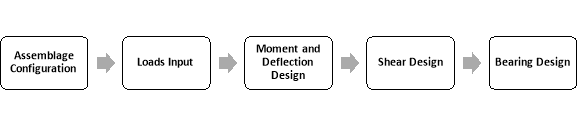
Figure 3-1: Design Steps of a beam in MASS™
Assemblage configuration is the first design step, where the material properties of the beam are entered or selected. Loads input is the second design step, where the loads and moments are applied to the beam. Using these loads, the program determines the corresponding load combinations. Moment and deflection design is the third design step. At this stage, the program designs the beam such that the moment resistance of the wall exceeds the maximum factored moment determined at the loads input stage. The deflection of the beam must also be less than the allowable deflection (as governed by the CSA S304-14 or as specified by the designer). Shear design is the forth design step, where the program designs the beam such that the shear resistance exceeds the shear due to the factored applied loading. This may require the addition of vertical reinforcement (stirrups). Bearing design is the last design step. During this step the bearing detailing is performed.
Assemblage Configuration
Assemblage configuration is the first step in developing a beam design. This step allows users to enter the material properties of the beam. To specify the properties of a beam:
- Enter the beam dimensions (length and height in mm)
- Select the type of masonry unit (hollow or semi-solid concrete)
- Choose the size and strength of the unit
- Choose the support conditions
- Choose the stress distribution at the supports
- Enter the bearing length
- Provide the masonry properties
- Provide steel properties
Beam Dimensions
The beam assemblage has three length terms: the actual length, the clear span, and the design length. The actual length, Lactual is the length of the beam that users enter. It is the total length of the beam, including any overhangs. The actual length of the beam is limited by clear span,Lclear span, and design length, Ldesign, requirements. The clear span is the width of the opening in a larger structure that the beam spans (shown in Figure 3‑2). The minimum clear span length allowed is half block length for concrete beams, and 200 mm for brick beams. The maximum clear span is limited only by restrictions on the design span. The design span is the extent of the beam used in the beam design. It is the distance between the centre of bearing at the left and right supports. This distance depends on the support conditions selected, as summarized in Table 3‑1.
Table 3‑1: Design Lengths Based on Support Conditions
|
Left Support Condition |
Right Support Condition |
Design Length of Beam |
|
Pinned or Roller |
Pinned or Roller |
Ldesign = Lclearspan + Centroid of left bearing + Centroid of left bearing |
|
Pinned or Roller |
Fixed |
Ldesign = Lclearspan + Centroid of left bearing |
|
Fixed |
Pinned or Roller |
Ldesign = Lclearspan + Centroid of right bearing |
|
Fixed |
Free |
Ldesign = Lclearspan |
For fixed supports, the centroid of the bearing is considered to be the edge of the support (where the support meets the clear span). For free ends, it is the end of the beam. For pinned and roller supports, the centroid of bearing is the centre of the stress distribution, and is considered the location of the point reaction on the assemblage to provide static equilibrium with the applied loads. The location of the centroid of bearing is measured from the end of the clear span closest to the support in question. For triangular stress distribution the centroid is located at a distance equal to 1/3 the bearing length; while for rectangular stress distribution, the centroid is located at a distance equal to 1/2 the bearing length. For more information on bearing dimensions refer to ‘Support Conditions’ section.
The minimum allowable design span is determined by the minimum clear span plus the bearing centroid distances. Additional limits are placed indirectly by CSA S304-14: 11.2.7, which describes the design of deep beams.
The actual length, clear span, and design length are shown in Figure 3‑2.
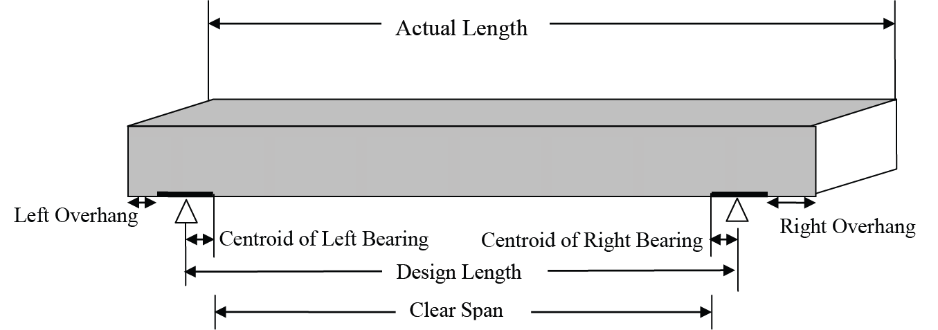
Figure 3‑2: Length, Clear Span, and Design Length of a Beam
The location of the supports, with respect to the left end of the beam, depends on the bearing length and the left and right over hang. The bearing length is the length of the bearing plate.
The overhangs at the left and right ends of the beam are the distance between the outer end of the bearing length and the end of the beam. The left overhang is defined by the smallest distance, that when added to the bearing length, yields a modular overlap. The left overhang is not allowed to be greater than a modular distance (½ a block length), or less than zero. The right overhang for non-cantilevered beams is the actual length remaining when the left overhang, both bearing lengths, and clear span are subtracted from beam length. The right overhang for cantilevered beams is the actual length remaining when the left overhang, the left bearing length, and the clear span are subtracted from the actual beam length. The right overhang must be less than 300 mm and greater than zero. The overhangs are unsupported lengths that are not considered in the engineering calculations. The limits placed on the overhangs ensure that the beam can be treated as a single span beam.
As an example, a beam with an actual length of 3200 mm is shown in Figure 3‑3.
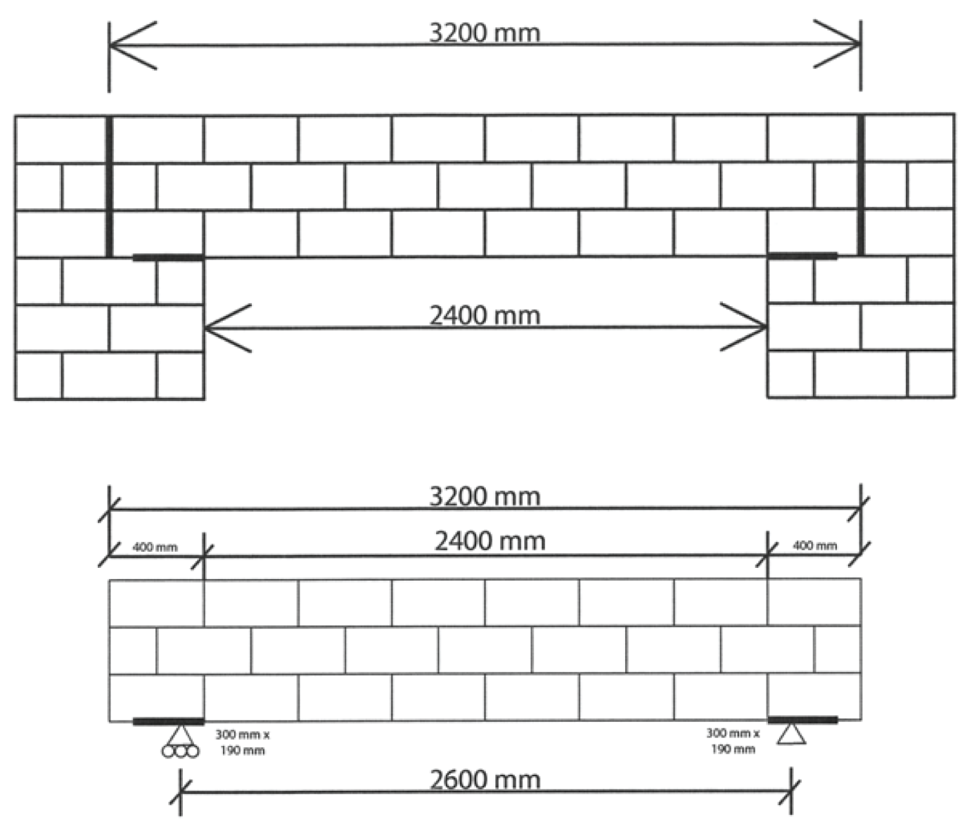
Figure 3‑2: Beam Within a Larger Structure
For a bearing length of 300 mm, the left overhang is 100 mm (because 300 mm + 100 mm yields a modular overlap of 400 mm). The clear span is calculated as follows
Lclearspan = Lactual – Lleftbearing – Lrightbearing -2 x Lleftoverhang
=3200mm – 300mm – 300mm – 2x100mm
=2400mm
For bearings with a triangular stress distribution, the centroid of the bearing occurs 1/3 of the way through the bearing length.
The centroid of the bearing plate in this case is 300/3=100 mm. Using Table 3‑1: Design Lengths Based on Support Conditions, the design length is calculated as follows
Ldesign = Lclearspan + centroid of left bearing + centroid of right bearing
=2400mm + 100mm + 100mm
=2600mm
Aside from the actual length that must be specified, users must also provide the height of the beam. The limiting minimum value for beam height is one block height for concrete block beams and 150 mm for clay brick beams. These are arbitrary limits set based on practical beam construction. The maximum height of the beam is determined by the ratio of design span to design height as given in CSA S304-14: 11.2.7; since this version of the program does not allow for the design of deep beams.
A beam with an actual length of 2900 mm and a height of 590 mm has been specified in Figure 3‑4. Notice that, when performing the assemblage configuration design step, the Assemblage Configuration button is outlined in blue.
For beams that are not modular in actual length, cut-off blocks are placed at the right side of the beam and are outlined in red to indicate a constructability concern. The program always forces the left side of the beam to start at either the beginning of a unit or at the half length of a unit. For beams that are not modular in height, cut-off blocks are placed at the top of the beam and are outlined in red to indicate a constructability concern. The program always forces the bottom course of the beam to begin at a whole unit or half unit.
*Note: The program recognises either a modular dimension or a modular minus 10 mm, or anything in between, as being composed of full blocks, however the value entered is the one used in design calculations. It is recommended that the mortar joint at the top of the beam not be included in the height of the modelled beam. Dimensions that are non-modular require units to be cut on-site. This may increase construction cost.
As soon as the assemblage dimensions are entered, an assemblage drawing is available. The actual length and the clear span are labelled in the assemblage drawing, as shown in Figure 3‑4. Notice the program automatically determines a clear span (in this case, 2100 mm). Once the beam dimensions are entered, the Loads Input button is activated in red, indicating that at this stage it is possible to move on to the loads input design step. This is because the program provides default values for all other properties in the assemblage configuration design step. Users, however, may wish to change the default properties.
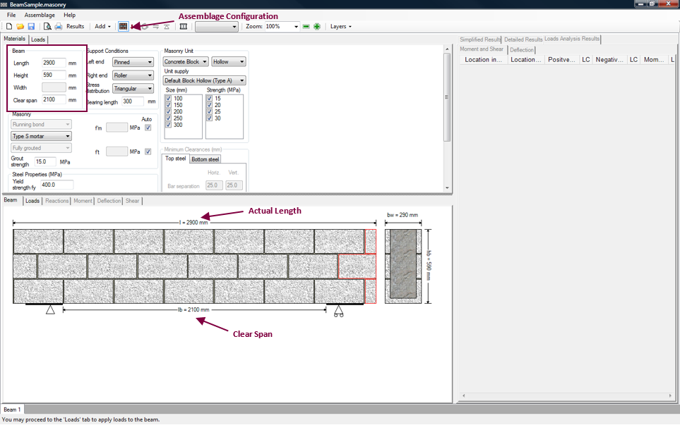
Figure 3‑4: Entering Dimensions of a Beam
Any changes that are made to the length of the beam are added to or subtracted from the right overhang, as long as the right overhang has a minimum length of 0 mm and does not exceed 300 mm.
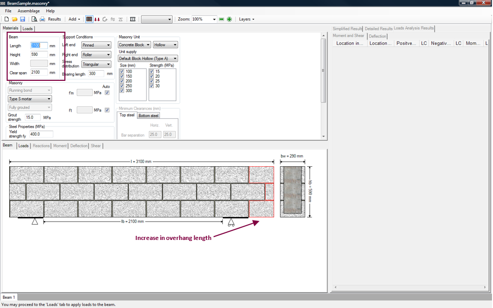
Figure 3‑5: Increase in Length over right support
As can be seen in Figure 3‑5, the overhang has increased by 200 mm:
Overhang Increase = Lactual_new – Lactual_previous
=3100mm – 2900mm
=200mm
Nevertheless, the clear span has remained the same, because the right overhang does not exceed 300 mm:
Loverhang_new = Loverhang_previous + Overhang Increase
= 100mm + 200mm
=300mm
To return to the beam configuration shown in Figure 3‑4, enter an actual length of 2900 mm. What happens if the actual beam length shown in Figure 3‑4? To accommodate this value, the overhang increases by 300 mm:
Overhang Increase = Lactual_new – Lactual_previous
=3200mm – 2900mm
=300mm
This increases the right overhang from 100 mm to 400 mm:
Loverhang_new = Loverhang_previous + Overhang Increase
= 100mm + 300mm
=400mm
This overhang value exceeds the maximum permitted value of 300 mm. Therefore, the program adjusts the clear span by the same amount the beam length is altered by:
Lclearspan_new = Lclearspan_previous + (Lactual_new – Lactual_previous)
= 2100mm + 300mm
=2400mm
This change in the clear span can be seen in Figure 3‑6. Notice that because the length entered is modular, the concrete blocks on the right end of the beam are no longer outlined in red. The dimensions entered in Figure 3‑6 are used in the remainder of this chapter.
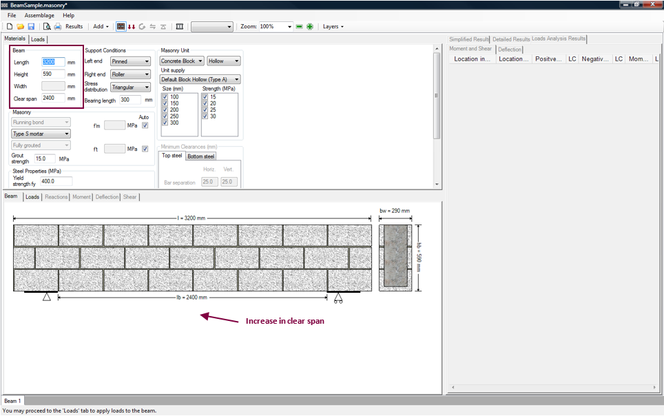
Figure 3‑6: Increase in Clear Span
*Note: If a user changes the clear span, the length of the beam is altered in the same manner, ensuring that the overhang on the right side of the beam is at least 0 mm in length, but does not exceed 300 mm.
Below the height textbox is the textbox for the width of the beam, shaded in grey. This indicates that the program in this case provides a value for the width of the beam, but this value cannot be directly altered by users. To alter this value when using concrete units, users need to select the unit size, as discussed under the ‘Choose the type of Masonry Unit’ section.
The width can be directly altered if the user is designing a brick beam. A minimum width of twice the smallest brick size, plus 50 mm of grouted cavity, as required by CSA S304-14: 11.3.4.4.
Type of Masonry Unit
For the beam module, MASS supports the use of clay bricks or concrete blocks, which can be selected using the masonry unit drop-down box, as shown in Figure 3‑7.
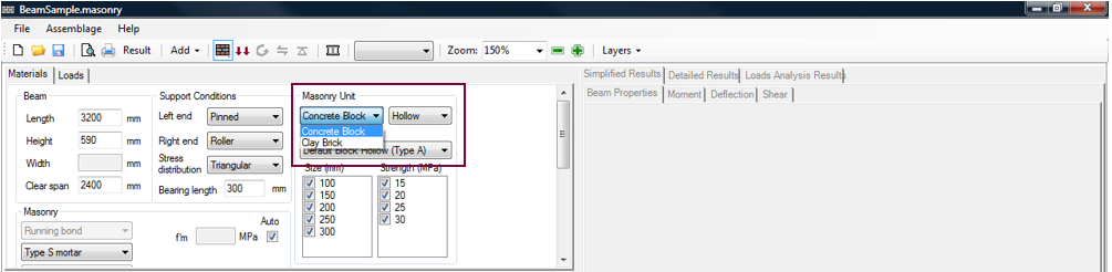
Figure 3‑7: Choosing the Type of Masonry Unit
Brick types with the following solidity are provided: hollow and solid. Block types with the following solidity are provided: hollow, semi-solid, half-high, half-block, and bond block. The default concrete unit types are shown in Figure 3‑8.
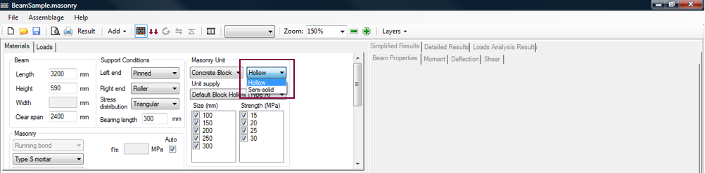
Figure 3‑8: Choosing the Solidity of a Masonry Unit
Users can also specify the unit supply of the masonry unit. This unit supply list contains default block types based on the solidity selected. For a block with a hollow solidity, the unit supplies available by default are shown in Figure 3‑9.
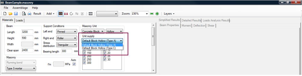
Figure 3‑9: Choosing the Unit Supply
The unit supply lists also includes customized units if they have been entered into the masonry unit database.
*Note: In addition to the available block types, a user is also able to create a new unit with customized properties using the Masonry Unit Database.
The classification of concrete block properties is governed by CSA A165.1-4 Table 1 – Table 4. For additional information on masonry unit properties, refer to page 144 of [1].
Size and Strength of Masonry Unit
Nominal dimensions of a masonry unit include ½ mortar bed thickness on each surface, adding 10 mm to each actual dimension. In the program, for concrete blocks, the size of the block refers to the nominal thickness, t + 10mm mortar joint. For bricks, the size is the actual dimension.
The strength selection (Figure 3‑10) pertains to the compressive strength of the unit f’unit. The compressive strength of the unit is the resistance to pressure applied perpendicular to the bed plane. Therefore it depends on the compressive strength of the material, the percent solid, and the shape of the unit. This compressive strength of a unit f’unit, contributes to the determination of compressive strength of the beam, f’m (governed by CSA S304- 14, Tables 3 and 4). The compressive strength of an assemblage takes into account the mortar and grout, as discussed in the ‘Choose the type of Masonry Unit’ section.
The unit strengths available for design depend on the supplier. The values provided in the program automatically are the typical values used in masonry construction. By default, the program leaves all possible sizes and strengths checked-on, as shown in Figure 3‑10.
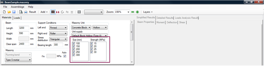
Figure 3‑10: Choosing the Size and Strength of a Masonry Unit (Hollow Concrete Block)
During the moment and deflection design step, the program iterates through these possible values, beginning with the smallest and weakest block, and selects the first of these that meets the engineering requirements. The default concrete block sizes available include 10, 15, 20, 25, and 30 cm units. The default block strengths include 15, 20, 25, and 30 MPa. Users can also select the specific size and strength of the unit, by checking-off all other unit sizes and strengths.
*Note: In some locations in Canada 30 MPa blocks may not be readily available.
For bricks, the default size available is 190 mm. For solid bricks the default brick strength available is 55 MPa (CSA S304-14 Table 3).
Support Conditions
The support conditions should be specified prior to the application of any loads. For beams, the support conditions supported by MASS™ are summarized in Table 3‑2: Support Conditions.
|
Left End |
Right End |
| Fixed | Non (cantilever) |
| Fixed | Roller |
| Fixed | Pinned |
| Fixed | Fixed |
| Pinned | Roller |
| Pinned | Pinned |
| Pinned | Fixed |
Notice, in this version of the program, the beam is only permitted to be cantilevered on the right side, the left side is fixed.
To select the left support condition of a beam using MASS™, click on the drop-down box marked ‘Left end’, as shown in Figure 3‑12. To select the right support condition of a beam using MASS™, click on the drop-down box marked ‘Right end’. The default beam support conditions are pinned-roller. The support conditions chosen are reflected in the beam drawing in the bottom window of Figure 3‑12.
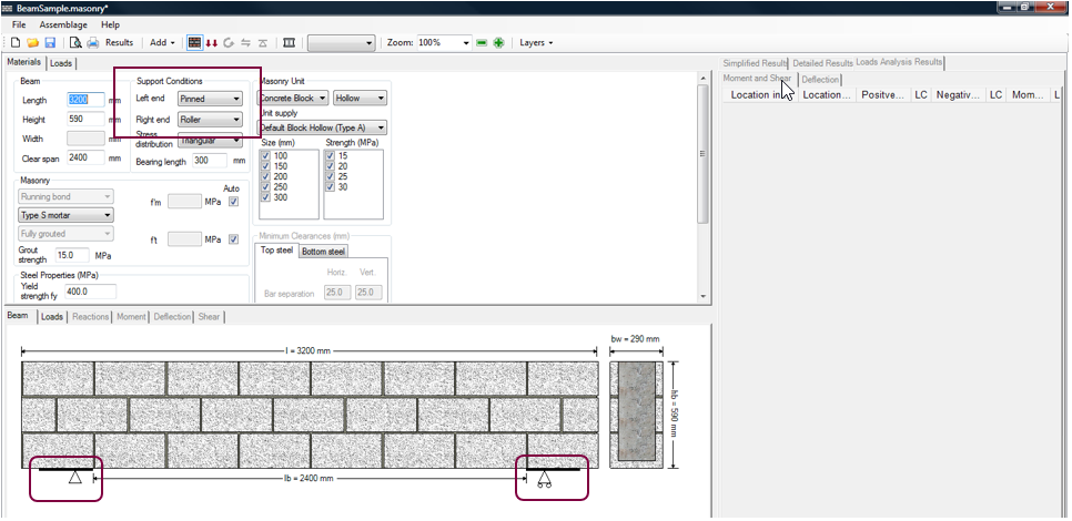
Figure 3‑12: Choosing the Support Conditions
For the beam module only, the stress distribution (under concentrated loads) at the supports must be provided. To select the stress distribution at the supports click on the drop-down box marked ‘Stress distribution’, as shown in Figure 3‑13.
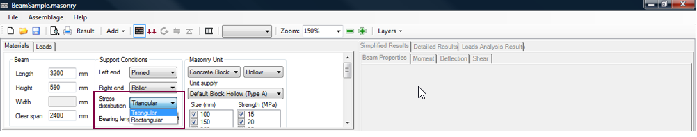
Figure 3‑13: Choosing Stress Distribution
*Note: The stress distribution selected applies for both bearing plates (except for cantilevered beams, which do not have a bearing plate on the right side of the beam).
The distribution of the reaction force on the bearing area is modelled either as a uniform distribution (rectangular distribution, as shown in Figure 3‑14) or one that is zero at the end of the bearing length and reaches a maximum at the clear span end (triangular distribution, as shown in Figure 3‑15). CSA S304-14: 7.14.1.1 indicates that the stress distribution for bearing design is assumed to be triangular, unless the bearing length is 300 mm or greater, in which case it is assumed to be uniform. A uniform stress distribution can be achieved by using a rocker plate between the bearing plate and the beam.
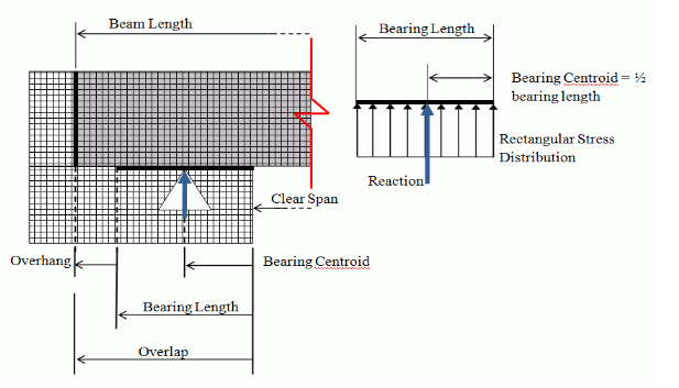
Figure 3‑14: Rectangular Stress Distribution
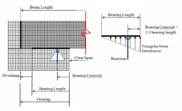
Figure 3‑15: Triangular Stress Distribution
The stress distribution does not apply to fixed or cantilevered end conditions. For a fixed end, the bearing reaction is considered to be concentrated at the end where it meets the clear span. For a free end (cantilevered), there is no support and therefore no bearing reaction.
The bearing length of the bearing plate must also be provided. The bearing length begins at the end of the clear span and goes outward towards the ends of the beam (shown in Figure 3‑14 and Figure 3‑15). However, this does not apply for all types of end fixity; there is no bearing length for the free end of a cantilever beam.
The lower limit for bearing length (for both reactions at supports, and point loads) is 50 mm (limit imposed by the program, not by the CSA Standards). MASS™ does not establish an upper limit for the bearing length.
Masonry Properties
Users can specify additional masonry properties; such as the bond pattern, mortar type, grouting pattern, compressive strength of the assemblage, tensile strength of assemblage, and grout strength.
MASS™ only accommodates a running bond configuration in the beam module (CSA S304-14: 11.1.3). Running bond configuration occurs when blocks in a higher course are placed such that the mid-section of each block is aligned with the vertical mortar joints of the lower course, as shown in Figure 3‑16.
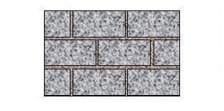
Figure 3‑16: Bond Configuration (Running Bond)
Alternative alignments are permitted in other masonry assemblages, but MASS™ only supports a running bond configuration for beam design. For instance, blocks can be laid with one-third overlap. A one-fourth overlap is however the minimum.
To change the mortar type select Type N or Type S using the drop-down box shown in Figure 3‑17.
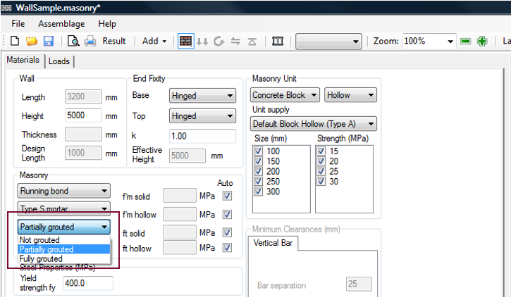
Figure 3‑17: Choosing Mortar Type
In general, there are five grades of masonry mortar (Types M, S, N, O, and K) that are distinguished by their proportions of lime, cement, and sand, and the resulting properties in terms of compressive strength, ductility, and workability. Only Type S and Type N are currently recommended for structural work, and therefore are the only two mortar types available within the program. Type S is a high compressive strength mortar recommended for structural applications and is used in the vast majority of masonry projects. Type N is a more workable but lower strength mortar used for low-stress bearing and veneer applications. Although strong, Type M has high vapour porosity and poor workability. Type O and Type K are primarily for restoration work.
*Note: Types M, S, N, O, and K are arbitrary letters, every other letter taken from the words Mason Work and have no meaning in terms of the mortar properties.
In the beam module, the only grouting pattern permitted is fully grouted (CSA S304-14: 11.1.3). This is because grout is required to anchor horizontal steel, which is required in beams, according to CSA S304-14: 11.2.3.
To change the grout strength enter the new grout strength into the textbox, as shown in Figure 3‑18. Press Enter on the keyboard. The grout strength entered must meet requirements of CSA A179.
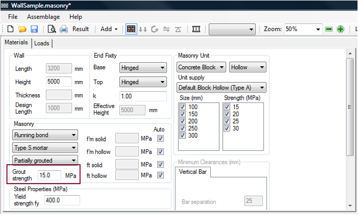
Figure 3‑18: Entering a New Grout Strength
The program uses a default value for the compressive strength of grout of 15 MPa. This value is based on the expected compressive strength of in-situ grout, as indicated in Clause 12.4.1.2 of CSA S304-14.
The compressive strength of grout by proportion, in accordance to Clause 7.1.2.3 of CSA A179-14, is on the order of 10 to 12 MPa. However, the strength of in-situ grout is higher than the strength of cylinders cast in non-absorbent moulds because suction from the masonry units reduces the water content in the grout. Clause 12.4.1.2 of CSA S304-14 indicates that the in-situ grout strength shall be taken as 1.5 times the 28 day grout cylinder strength test; hence, the compressive strength for in-situ grout is on the order of 15 to 18 MPa.
*Note: Stronger grout (compressive strength above 20 MPa) tends to have a lower water content, and thus is less fluid. As a result, it is often difficult to fill the necessary cells or cavities, resulting in poorer performance. For this reason, using a stronger grout to match the compressive strength of the masonry units or to satisfy development length requirements is not recommended. For more information on grout strength, refer to CSA A179-14: 7.2.3.
The compressive and tensile strength values of an assemblage are calculated automatically within the program using Table 3 and Table 4 in CSA S304-14, and depend on the masonry unit type selected. Upon the completion of the moment design step, (or as soon as the user selects only one masonry unit size and strength, the compressive and tensile strength used in the design are displayed in the textbox (as shown for example, in Figure 3‑30).
Users are permitted to override selected compressive and tensile strength values. The compressive values entered by users must be based on prism tests that have been performed in accordance to CSA S304-14: 5.1 and CSA S304-14: 5.2. To override a compressive strength value, uncheck the ‘Auto’ box shown in Figure 3‑19, and enter the compressive strength value into the textbox. Press Enter on the keyboard. To override a tensile strength value, uncheck the ‘Auto’ check-box, and enter the tensile strength value into the textbox. Press Enter on the keyboard. For example, for a beam, users are permitted to enter test values for f’m , and f’t.
Uncheck the ‘Auto’ check-box next to each value and then enter appropriate compressive strength and tensile strength values, as shown in Figure 3‑19.
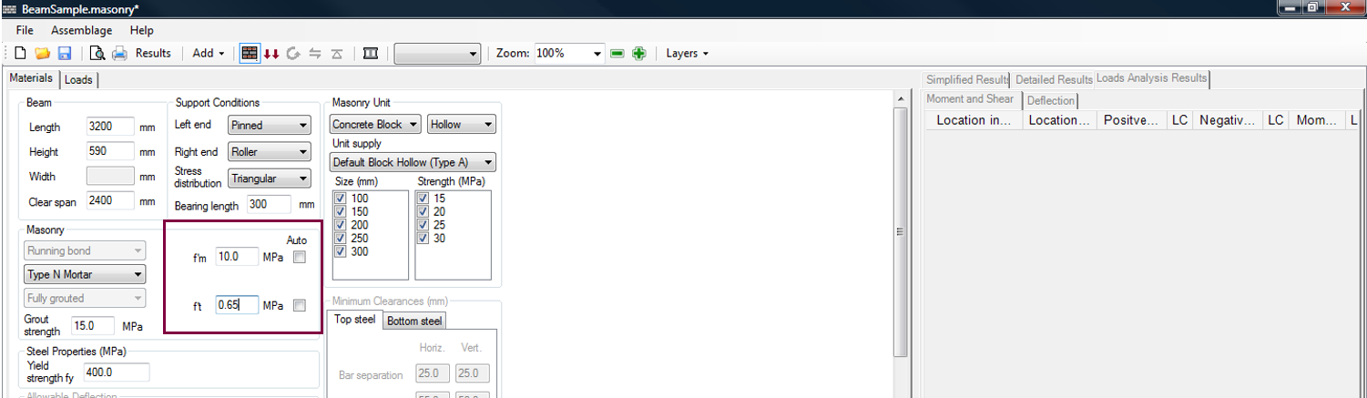
Figure 3‑19: Entering a New Compressive and Tensile Strength
It is common to perform prism tests to gain additional capacity. Because masonry can fail under compression, designers perform prism tests to determine compressive strength values. However, if users check-off the ‘Auto’ box, the program requires users to provide both the compressive and tensile strengths. It is acceptable to use compressive strength values determined using prism tests, but enter tensile strength values using Table 5 from CSA S304-14. Figure 3‑19 For the remainder of this chapter, the ‘Auto’ check-box is checked-on.
*Note: The compressive strength values used in the program are limited to 40 MPa. The tensile strengths used in the program are limited to 2 MPa. For more information, refer to pages 196 and 197 of [1].
Steel Properties
At this stage, the only steel property users are permitted to specify is the steel yield strength. The yield strength is defaulted to 400 MPa, as shown in Figure 3‑20. To alter the yield strength, enter a new value in the textbox. Press Enter on the keyboard.
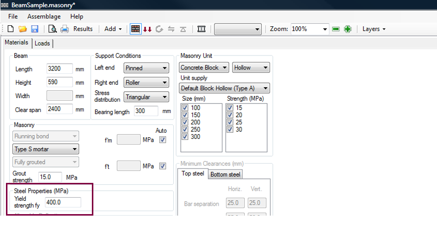
Figure 3‑20: Steel Yield Strength text box
There are three popular grades of steel: 300, 400, and 500. Only the 400-grade is widely available and is used on the vast majority of applications. 300-grade reinforcement bars are available in 10 mm and 15 mm sizes. 500-grade reinforcement bars in all sizes are available through special order to steel mills.
Other horizontal steel properties (for example, bar size, bar separation, etc.) can only be altered once the moment and deflection design step has been completed.
Allowable Deflection
There are two allowable deflection limits that can be altered by users; the live+long term deflection and the total deflection (Figure 3‑21).
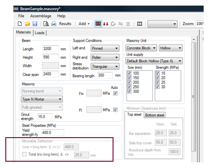
Figure 3‑21: Allowable Deflection
The allowable deflection limits cannot be changed by users until the moment and deflection design step is performed. Refer to the section on Moment and Deflection Design for more details on altering the allowable deflection.
Constructability Concerns
An additional feature of the program is a textbox that provides feedback of potential constructability concerns. These consist of potential problems that may arise on the construction site due to the particular design the engineer has selected. These constructability concerns are shown in a designated textbox (shown in Figure 3‑22), as well as in the print outs and (where applicable) in the assemblage illustrations.
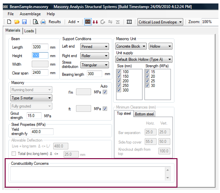
Figure 3‑22: Constructability Concerns
*Note: Constructability concerns are only warnings. The program can provide a successful design even in the presence of a constructability concern. It is up to the discretion of the designer to adjust the design to ensure it can be reasonably constructed.
While constructability concerns initially occur during the assemblage configuration design step, the ‘Constructability Concerns’ textbox provides interactive feedback only once the moment and deflection design step has been performed.
At this time, users can proceed to the loads input design step. Be aware however, that during this design step the assemblage properties previously selected cannot be altered.
Loads Input
Loads input is the second step in developing a beam design. This step allows users to enter the loads that are applied to the assemblage. Loads are applied in a similar manner for all assemblage types:
- Click on the Loads Input button
 , or on the Loads tab
 - Choose the importance category (low, normal, high, post-disaster)
- Click on Add Load
- Enter the load properties (type, distribution, un-factored magnitude, and units)
Loads Input
There are two ways to begin the loads input design step: click on the Loads Input or the Loads tab. Notice that when performing the loads input design step, the Loads Input button is outlined in blue, as shown in Figure 3‑23. Upon moving into the load inputs design step, the program automatically displays the assemblage drawing in the Loads tab (bottom window).
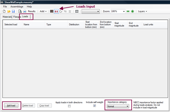
Figure 3‑23: Loads Input Design Step
Importance Category
The importance category is selected using the drop-down box under the ‘Importance category’ title shown in Figure 3‑23. The importance category specifies the importance of a building, determined based on the hazard a building failure could pose.
Load Properties
To add a load, click on the Add Load button shown in Figure 3-23. For more information on adding, copying, and deleting loads, refer to the Loads Input section.
The program allows for the selection of the following loads for the beam assemblage: dead, live, snow, wind, earthquake, storage, controlled fluid, soil, and contraction/expansion. These can be selected using the drop-down box found under the ‘Type’ column, shown in Figure 3‑24.
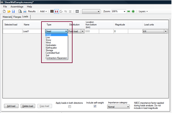
Figure 3‑24: Choosing a Load Type
*Note: A contraction/expansion load can only be placed on the beam once. A storage load and controlled fluid load should not be placed simultaneously on the assemblage. This is a limitation of the program. Storage loads and occupancy loads are classified as live loads according to CSA S304-14: 4.1.1, with different load factors (refer to Notes 3 and 4 of the in CSA S304-14: 4.2.2.2). Internally, however, the program processes all permanent live loads together, therefore users cannot have both live storage and live controlled fluid loads on the same assemblage.
Similarly to choosing a load type, users can choose the load distribution using the drop-down box found under the ‘Distribution’ column. The load distribution opportunities are extensive. Load distributions that can be applied to a beam include point loads, line loads (uniformly distributed, triangular, and trapezoidal), moments, and axial loads (for the contraction/expansion load type only).
In the beam module, the program allows users to enter a ‘Start from the left (mm)’ and an ‘End location from the left (mm)’ as well as a ‘Start magnitude’ and ‘End magnitude’ for an unfactored load or moment. This provides a large versatility in the type of loads that can be applied.
*Note: The start and end magnitude of a line load must be of the same sign. To place a line load that has a start magnitude of -5 kN and an end magnitude of 5 kN, users are required to split the load into two line loads.
Loads applied at the ends of the beam, past the support locations (at the overhangs), are not considered in the moment, deflection, and shear engineering calculations. Instead, it is assumed that these loads are passed directly into the supports. The bearing capacity at the supports is checked to ensure the bearing plate can withstand these loads. Refer to the section on Bearing Design for more details.
In Figure 3‑25 an unfactored dead load of 10 kN/m, and an unfactored live load of 5 kN/m are applied along the length of the beam (beginning at 0 mm and ending at 3200 mm).
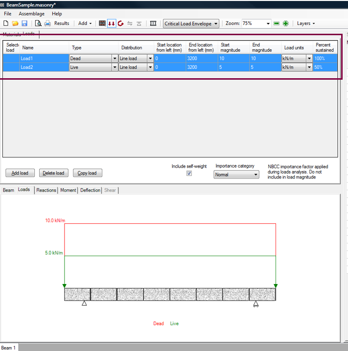
Figure 3‑25: Entering Load Properties
*Note: According to MASS sign convention, a downward applied load is considered a positive load. A moment applied in the clockwise direction is considered a positive moment.
*Note: The un-factored magnitude of the previously added load must be specified before a new load is added.
Once a load is entered, the Moment and Deflection Design button becomes red, indicating that it is possible to move on to the next design step. This is because the program provides default values for all other properties in the loads input design step. Users, however, may wish to change the default properties.
The units of the load can be specified using one of the following units: kN/m, N/m, lb/ft, or kip/ft simply by selecting the drop-down box under the ‘Load units’ column. The percentage of the load being sustained can be entered in the ‘Percentage sustained’ column, shown in Figure 3‑25. The default percentage sustained values for each load type are shown in Table 3‑3: Percentage of Load Sustained.
Table 3‑3: Percentage of Load Sustained
Load Type: Percent Sustained
Dead: 100% .
Live: 50% .
Snow: 0% .
Wind: 0% .
Earthquake: 0%. .
Storage: 100%
Controlled Fluid: 100%
Vertical Soil: 100%
These default values can be altered for all load types, except for: snow, wind and earthquake loads. Snow, wind, and earthquake loads are expected to vary in time, and thus the percentage sustained cannot be altered from 0% for these load types.
A specific load can be viewed under the Loads tab by clicking on the box under the ‘Selected Load’ of that particular load. Multiple loads can be viewed by holding down Shift key, and selecting the loads to display. Figure 3‑25 shows two selected loads that are displayed in the loads drawing. The applied loads that are being displayed are highlighted in blue in the input table. In the loads drawing, the load colours correspond to the load types (refer to the section on Drawings).
Critical Load Envelope
With each new load added, the program uses the importance category selected in order determine the corresponding factored load combinations based on CSA S304-14: 4.2.2. To view all applicable load combinations click on the Critical Load Envelope drop-down box, as shown in Figure 3‑26. The critical load envelope is the default setting.
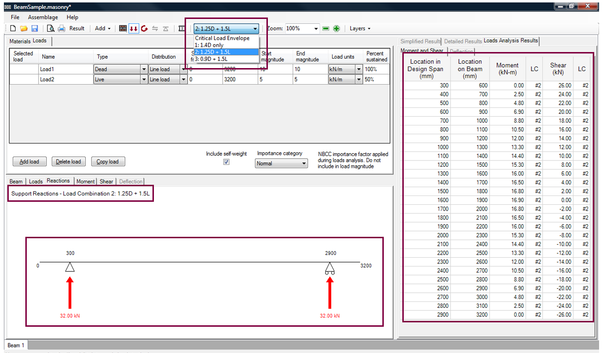
Figure 3‑26: Viewing All Applicable Load Combinations
Notice that the drawings under the Reactions, Moment, and Shear tabs, as well as the Loads Analysis Results tab change to reflect the selected load combination. For instructions on viewing loads analysis results for different load combinations, refer to the section on Load Analysis Results.
*Note: Even though users can select to view the information for the critical load envelope, or for any applicable load combination, the program always designs the beam to withstand the critical load combination.
To determine which load combination is critical prior to performing the moment and deflection design step, choose critical load envelope in the Critical Load Envelope drop-down box. In the right window, the Loads Analysis Results → Moment and Shear tab is open by default. The ‘LC’ column provides the load combination number that is critical. The load combination corresponding to this number is listed in the Critical Load Envelope drop-down box. In the beam shown in Figure 3‑27, the critical load combination number is 2.
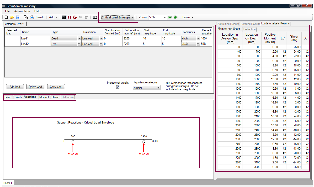
Figure 3‑27: Determining the Critical Load Combination at the Loads Input Design Stage
To create the critical load envelope for the moment drawing, MASS™ takes the resulting moment diagram values from all the load combinations drawing, and creates an envelope based on the maximum positive and negative moment values along the length of the beam. The applicable load combinations are the load combinations that are listed in the Critical Load Envelope drop-down box.
Self-Weight
To the left of the ‘Importance category’ drop-down box is the ‘Include self-weight’ check-box. The self-weight is included in the load calculations by default. Users can choose to exclude the self-weight of the assemblage by checking-off the ‘Include self-weight’ check-box, shown in Figure 3‑28.
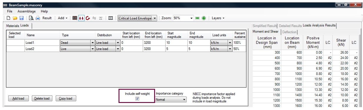
Figure 3‑28: Including the Self-Weight
The program calculates an initial self-weight based on the masonry properties selected in the assemblage configuration design step. The self-weight is included as a dead load.
MASS™ determines the self-weight of a beam,Psw, per metre of beam length (kN/m), by adding the weight of the masonry units and the weight of the grout.
For example, for a beam designed with solid bricks, the self-weight is determined as follows:
Psw = Pb{(2wunit x Yunit)} + [(Bw – 2Wunit) X 2350}} x 9.81
where Hbis the height of the beam, Wunit is the weight of a single solid brick, Yunit is the density of the unit, and bw is the width of the beam.
For a beam designed with concrete block units, the self-weight is calculated as follows:
Psw = hb{(%solid x bw x yunit) + [(100 – %solid) x bw x 2350]} x 9.81
where %solid is the percentage of the volume of the block that is solid material (as opposed to cells). Notice, the weight of the reinforcing bars is not included in the self-weight calculations.
Because the self-weight of a beam depends on the masonry unit size, it is possible for the self-weight of the beam to change during the moment design step or the shear design step (while the program iterates through all the selected masonry properties).
Upon the completion of the loads input design step, users can proceed to the moment and deflection design step.
Moment and Deflection Design
Moment and deflection design is the third step in developing a beam design. In this step the program iterates through the selected parameters and designs a beam such that the total moment resistance due to masonry and all steel reinforcement is greater than or equal to the largest moment at the critical section of the beam, for any load combination of input loads.
The moment resistance is calculated for each load combination by setting the factored axial load equal to the axial resistance and solving for the corresponding moment resistance. The live+long term and immediate+long term deflections are also calculated and compared to the deflection limits set by users.
In order run the moment and deflection design click on the Moment and Deflection Design button, as shown in Figure 3‑29.

Figure 3‑29: Moment and Deflection Design Step
Notice that when performing the moment and design step, the Moment and Deflection design button is outlined in blue. Notice, also, that prior to running the moment and deflection design step, the allowable deflection box is disabled. The minimum clearances box is also disabled, and therefore users cannot specify the horizontal reinforcement properties.
Moment and Deflection Design Step: Successful Design
Highlighted in green are the masonry unit properties and the steel properties that provide a successful design, as can be seen in Figure 3‑30. Notice users cannot alter the top steel or bottom steel properties (including the minimum clearances) until the moment and deflection design step has begun. Notice also that the design selections are reflected in the beam drawing in the bottom window.
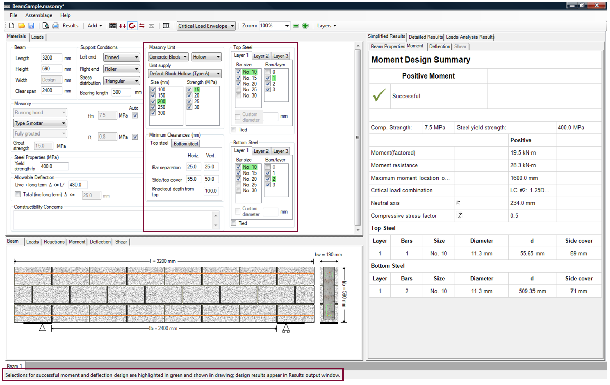
Figure 3‑30: Moment Design (Successful)
The status bar at the bottom of the page informs users whether or not a successful design is found. The Simplified Results → Moment tab is displayed by default during the moment and deflection design step, and provides summarized moment results. For more information on reading the simplified results provided in the Moment tab or in the Deflection tab refer to the Simplified Results section.
*Note: Due to the large number of iterations the program performs, it may take up to several minutes to reach a successful design. If the program requires more than several seconds to reach a solution, the smaller weaker blocks or larger spacings and smaller bar sizes do not provide enough capacity. In this case, users can readily de-select some of the early iterations in the midst of the design process. This significantly speeds up the program. For more information on the design strategy of the program, refer to the Moment and Deflection Design Strategy section.
Once the moment and deflection design step is performed, the Shear Design button becomes red, indicating that at this stage it is possible to move on to the shear design step. This is because the program provides default values for the shear design step.
Top and Bottom Steel
Upon the completion of a successful or unsuccessful moment and deflection design, users may wish to alter the design provided by the program (prior to moving on to the shear design step). Under the Materials tab, any of the material properties previously entered or selected can be altered. The program automatically re-triggers the moment and deflection design step if any of the check-box material selections are altered. For new values that are entered into a textbox (for instance, a compressive strength), enter the new value, and then press Enter on the keyboard to re-trigger a design.
*Note: To add new loads, click on the Loads tab. This reverts the program back to the loads input design step. Retriggering the Moment and Deflection Design button is necessary.
Users can now change the horizontal properties used in the design. The axial tensile and compressive strength of the horizontal steel is used to resist the axial compressive and tension stresses in a beam that arise from the bending moment stresses due to applied loads and/or moments. The horizontal steel provides the additional stiffness to minimise the deflection of the beam. Horizontal steel can be placed in several different ways:
- Using a U-shaped bond block, usually placed in the bottom course of a beam
- Perforating a course of blocks manually with a hammer
- Using special knock-out blocks
- Using double-wythe construction with a grout cavity
- Using lintel blocks (not available in MASS™)
The horizontal reinforcement placed in the beams is divided into three categories: the top steel (typically compression steel), the bottom steel (typically tension steel), and the intermediate steel. Users have the opportunity to specify multiple bar configurations by altering the top steel and bottom steel configurations. The program cycles through all possibilities to achieve a design that provides sufficient moment resistance and allows for the tension steel to yield at maximum stress. For more information on the beam design strategy MASS™ utilizes, refer to the Moment and Deflection Design Strategy section.
The horizontal steel bars are organized in layers as shown in Figure 3‑31. Each of the upper and lower bar groups are composed of as many as three layers of bars, each with as many as three bars. All of the bars in a particular layer must be of the same size, but different layers can have different bar sizes.
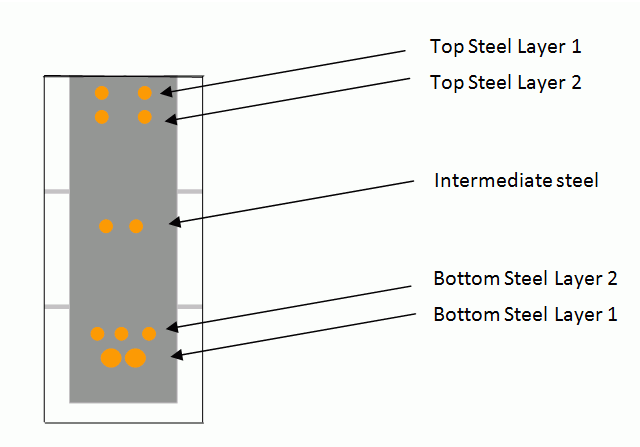
Figure 3‑31: Horizontal Reinforcement Layers
To alter the top steel or bottom steel configuration along the length of the beam:
- Select the layer tab (Layer 1, Layer 2, or Layer 3)
- Select the bar size (No. 10, 15, 20, 25, or 30)
- Select the number of bars per layer (0, 1, 2 or 3)
For instance, to alter the No. 10 bottom steel bars used in layer 1 (Figure 3‑30), click on the Layer 1 tab in the ‘Bottom Steel’ box. Then check-off the ‘No. 10’ check-box, as shown Figure 3‑32.

Figure 3‑32: Changing the Bar Size
Notice that with a No. 15 bar used in the design, the program no longer requires two bars in layer 1 to resist the applied loads. If users wish to place two bars in layer 1 anyway, this can be readily achieve by simply checking-off the ‘1’ check-box, as shown in Figure 3‑33.The program automatically selects the next number of bars/layer (in this case, 2).
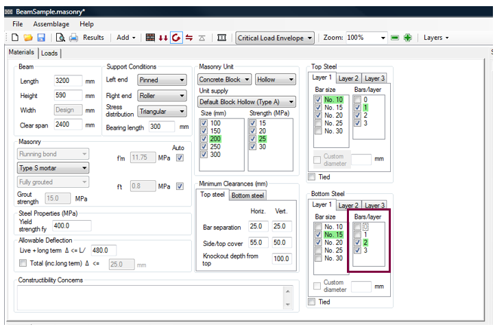
Figure 3‑33: Changing the Number of Bars/Layer
By default, bar sizes No. 10, No. 15, and No. 20 are checked-on. The No. 25 and No. 30 bars must be specifically selected by users to be included as a design possibility. For a bar size not specified in the check-box list, enter the bar diameter into the textbox labelled ‘Custom diameter’.
A custom diameter of 15.875 mm is specified Figure 3‑34. This diameter specified as 15.875 in millimetres is equivalent to 0.625=5/8 inches. Following the American reinforcement bar size convention, this is the diameter of a No. 5 bar. This bar size is not used in the remainder of the design.
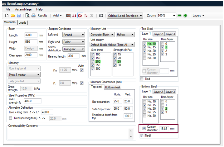
Figure 3‑34: Entering a Custom Bar Diameter
*Note: Imperial bar sizes must be entered in metric units in the custom diameter textbox.
The custom diameter size is limited to a 30 mm diameter bar. This feature was introduced to allow for imperial reinforcement bar sizes, which are used in some locations in Canada, particularly those in close proximity with the United States border.
In addition to selecting the number of bars per cell, and the bar size, users are also able to tie the top steel (typically compression steel) and/or the bottom steel (typically tension steel), as is indicated in Figure 3‑34.
In MASS™, in order for the compression reinforcement to be included in the moment and deflection calculations of beams, the steel must be tied. According to CSA S304-14: 11.2.6.4, reinforcement is considered to be tied if it is anchored by ties or stirrups not less than 6mm in diameter, and spaced not more than 16 bar diameters or 48 tie diameters apart, whichever is less.
According to CSA S304-14: 11.2.6.4, ties must be spaced no more than 16 bar diameters or 48 tie diameters, of at least 6 mm diameter each, for compression steel to be considered. This version of the program does not detail or check these requirements, but the user is still able to indicate whether that steel is tied to indicate whether the compression resistance is considered.
The reinforcement bars in compression must be tied to be considered in the moment resistance calculations. However, for reinforcement bars in tension, the tension force is included in the moment resistance calculations, independent of whether the bars are tied or not.
*Note: Since a length of steel can experience both compression and tension loading, it is not sufficient enough for users to simply exclude the compression steel altogether.
Intermediate Steel
For beam with a height greater than 600 mm, intermediate steel is used and it can contribute to both the tensile or compressive resistance of the member, depending on the loading conditions and support conditions of the beam. The intermediate steel can be used for compressive resistance only if the top or bottom steel layers (whichever are in compression) are tied.
Intermediate steel is automatically uniformly distributed in the beam by the program when the height of the beam exceeds 600 mm, following CSA S304-14: 11.2.6.3 requirements. A single No. 15 bar is placed per layer when the beam width is smaller or equal to 240 mm. The intermediate steel is centred horizontally in the middle of the beam if there is only one bar per layer. Two No. 15 bars (with a 25 mm bar separation) are placed per layer when the width of the beam is greater than 240 mm. When there are two bars per layer, the distance from the edge of each bar to the edge of the beam is set equal to the bottom steel side cover. For the single-bar layers and double-bar layers, the reinforcement layers are spaced at equal intervals of 400 mm.
While the program selects the bar size, bar spacing, and number of bars per layer of intermediate steel, users are, however, able to specify the location of the bottom layer of intermediate steel (refer to the ‘Minimum Clearances’ heading). The program places any additional layers at a vertical spacing of 400 mm until the top layer of intermediate steel is at a distance that is equal to or less than 400 mm from the top of the beam. Or until the distance between the top layer of intermediate steel and the lowest layer of top steel is equal to or less than 400 mm. In this case the top steel layer must contain as much reinforcement area as the intermediate steel layer.
Minimum Clearances
To count on the benefits of reinforcement placed in the beam, the reinforcement must be completely covered by mortar or grout and it should be protected from the external environment so it does not degrade. To accomplish that, minimum spaces between bars and between masonry surfaces should be provided. These minimum clearances are specified in CSA A371-14: 8.2.5.4.9 and 8.2.5.7.
MASS™ places limitations on the possible horizontal steel configurations, based on these minimum clearance values. The program contains default values for these minimum clearances; however, those values can be overridden.
These limitations can be manipulated by users using the ‘Minimum Clearances’ box shown in Figure 3‑35. To manipulate the minimum clearance values for reinforcement steel placed towards the bottom of the beam, click on the Bottom steel tab. The bottom steel configuration varies depending on the block size, as well as the following:
- Bar separation (horizontal and vertical)
- Side Cover
- Bottom Cover
- Intermediate bar location
To alter the bottom cover for example, type in the new bottom cover value into the ‘Vert.’ textbox (shown in Figure 3‑35), and press Enter. Notice that the minimum clearances values selected are reflected in beam drawing.
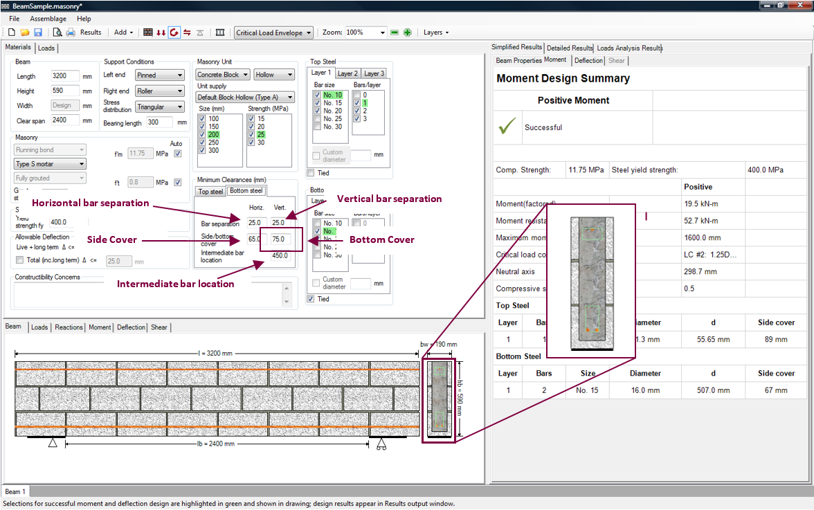
Figure 3‑35: Minimum Clearances (Bottom Steel)
Green boxes are displayed over the beam cross-section to indicate the space within which the reinforcement bars must fit (shown in Figure 3‑35).
To manipulate the minimum clearance values for reinforcement steel placed towards the top of the beam, click on the Top steel tab. In the top steel configuration varies depending on the block size, as well as the
- Bar separation (horizontal and vertical)
- Side cover
- Top cover
- Knockout depth
To alter the top cover for example, type in the new top cover value into the ‘Vert.’ textbox (shown in Figure 3‑36), and press Enter. Notice that the minimum clearances values selected are reflected in beam drawing.
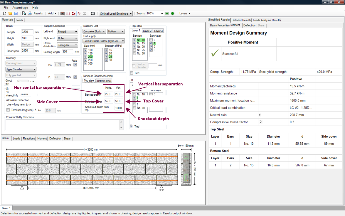 Figure 3‑36: Minimum Clearances (Top Steel)
The minimum clearances values users can alter are summarized in Figure 3‑37.
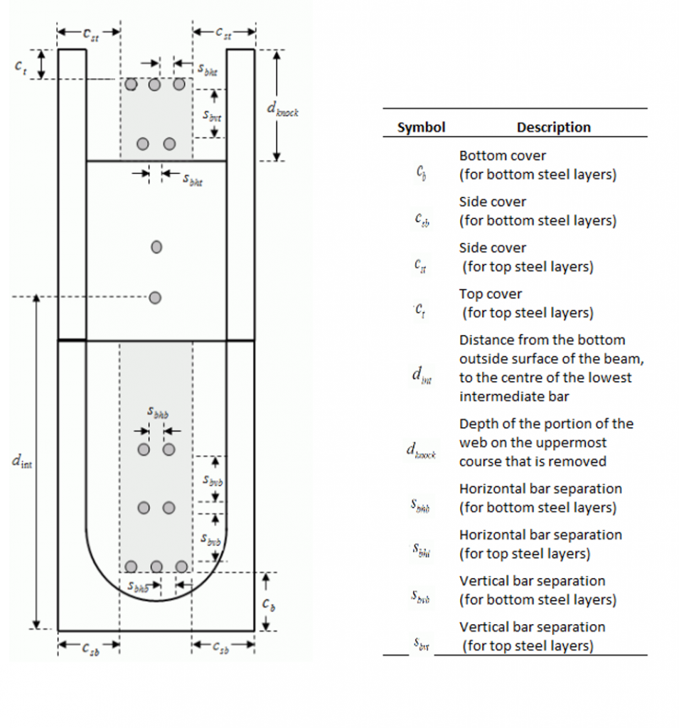
Figure 3-37: Bar clearance description
In general, the horizontal bar separations are used to place the bar (within each layer) symmetrically about the centre of the beam. The side cover values provide bounding boxes within which the top steel or bottom steel layers must fit. The side covers do not necessarily define position the actual positions of the bars; they serve as a limit only.
The vertical bar separations are used to place the bar layers with respect to one another. For the bottom steel, the first steel layer is placed using the bottom cover. For the top steel, the first steel layer is placed using the top cover. The knockout depth provides a bound within which the lowest top steel layer must fit. The knockout depth does not necessarily define the actual position of the lowest layer of top steel bars; it serves as a limit only.
For the intermediate steel, the bottom steel bar separations are used to place the intermediate steel bars. The bottom steel side cover provides the constraints within which the intermediate steel layers must fit. The intermediate bar location is used to place the first layer of intermediate steel (with respect to the bottom of the beam). Additional intermediate steel layers are placed at a spacing of 400 mm.
There are limitations placed by CSA Standards and the program on the minimum clearance values users can specify. The limitations placed on the side cover, bottom cover, and top cover, the bar separations (vertical and horizontal), the intermediate bar location, and the knockout depth are summarized in Table 3‑5: Limitations Placed on Minimum Clearances‑.
Table 3‑5: Limitations Placed on Minimum Clearances
| Minimum Clearance | Limitation | Default value |
| Side Cover | The side cover for a concrete block or hollow brick beam is limited to the lesser of the minimum face shell thickness plus 13 mm in accordance with CSA A371-14: 8.2.5.7.1 for course grout; or 40 mm in accordance with CSA A371-14: 8.2.5.7.1 and 8.2.5.7.3. The side cover for a double-wythe clay brick beam is limited to the lesser of the solid brick width plus 13 mm; or 40 mm in accordance with CSA A371-14: 8.2.5.7.1 and 8.2.5.7.3. For all masonry unit types, the side cover cannot exceed the width of the beam. | Varies depending on masonry unit type |
| Bottom Cover | The bottom cover is limited to 40 mm for all masonry unit types used in the program. This limit is dictated by CSA A371-14: 8.2.5.7.3. The program places a maximum limit of 200 mm. | 75 mm |
| Top Cover | The top cover must be at least 20 mm for all masonry unit types used in the program. This limit is dictated by CSA A371-14: 8.2.5.7.3. The program places a maximum limit of 200 mm. | 50 mm |
| Bar Separation
(Horizontal |
The lower limit for the vertical and horizontal bar separation is the greater of 25 mm or the largest bar diameter in accordance with CSA A37-14: 8.2.5.4.9.1. The upper limit for the vertical bar separation is 100 mm for all beam types.
The upper limit for horizontal bar separation is determined by the geometry of the beam. |
25 mm |
| Intermediate Bar Location | The lower limit for the intermediate bar location is 200 mm. This accommodates the situation where users wish to place a bar at the top of the bond block course. The upper limit imposed by the program is the bottom cover plus 400 mm. | 40 mm for blocks/brick with more than one course.
450 mm for double-wythe brick. |
| Knockout Depth | The lower limit is dictated by the space required to fit the top steel (taking into account the top cover). The upper limit for the depth is 150 mm. This provides the minimum amount of remaining web so that the block can be used in construction for typical 200 mm high units. | 100 mm (concrete blocks only) |
If users enter a minimum clearance value that exceeds the limitations specified in Table 3‑5: Limitations Placed on Minimum Clearances‑, the program adjusts the design. For example, if the horizontal bar separation of the bottom steel is increased such that two bars cannot fit within the side cover requirements, the program meets the design requirements by using a single bar, with an increased bar size.
Allowable Deflection
Part of the limit state design is checking for serviceability (durability, cracking, vibration, and deflections) under service loads. Excessive deflections of beams may produce cracking of walls or partitions supported by the beam, misalignment in wall openings (windows and doors), or can be visually uncomfortable to the occupants of the building.
The deflection in masonry beams is a consequence of the loads applied to that beam and the duration of the loads (creep and shrinkage). CSA S304-14: 11.4 establishes the procedure used to calculate the service load deflection in beams.
Once the moment design step is performed, the allowable deflection limits can be altered by users.
There are two allowable deflection limits that can be altered by users; the maximum live+long term deflection, and the maximum total deflection. The maximum allowable live+long term deflection is governed by CSA S304-14: 11.4.5, and cannot exceed L/480, where L is the design length of the beam (single span).
Users are permitted to reduce the maximum allowable live+long term deflection value (that is, increase the denominator). The maximum total deflection is the total immediate deflection and the long term deflection. This is an additional limit that users can place on the deflection, but is not required by CSA S304-14.
To alter the maximum allowable live+long term deflection limit, enter a new denominator into the textbox outline in Figure 3‑38.
The live+long term deflection must be limited in accordance to the provisions specified in CSA S304-14: 11.4.5.The user can also choose to place an additional limit on the total deflection (immediate+long term deflection). To limit to maximum total deflection, check-on the ‘Total (inc. long term)’ check-box, and enter the total deflection limit, in millimetres, as exemplified in Figure 3‑38.

Figure 3‑38: Allowable Deflection
Following the requirements established in CSA S304-14: 11.4, and using the values obtained from the moment design as well as the values input by the users, the program calculates the limit and total deflections, and compares these values to the maximum deflection allowed by the standard (CSA S304-14: 11.4.5), and to the maximum total deflection allowed by users (if applicable).
A successful design is achieved when the calculated deflection value is equal or less than the limiting deflections. If a successful design is not achieved, the program increases the stiffness of the beam according to the design loops (increasing bar size, bar number, unit strength, unit size). Refer to the Moment and Deflection Design Strategy section, for a complete description of the defection design strategy.
To view the deflection results, click on the Simplified Results → Deflection tab or the Detailed Results → Deflection tab. For more information on reading the results provided in the Deflection tab refer to the sections on Simplified Results and Detailed Results.
Moment and Deflection: Unsuccessful Design
An unsuccessful moment design is marked with a red ‘X’ in the ‘Moment Design Summary’ (shown in Figure 3‑39).
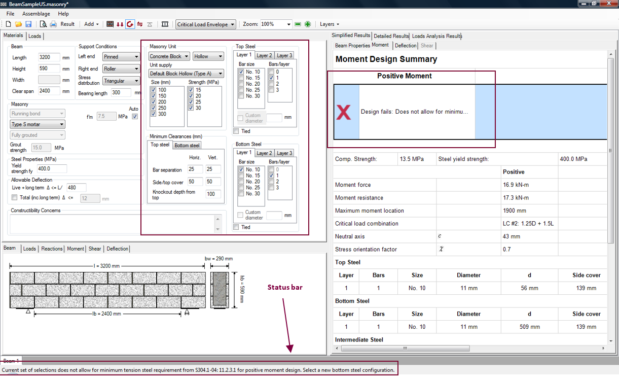 Figure 3‑39: Moment and Deflection Design (Unsuccessful)
Figure 3‑39 shows that many design selection have been de-selected (by users), meaning these properties are not to be included as possible parameters for the design. The selected properties did not result in a beam design that could resist the applied loads.
The status bar at the bottom of the page also informs users whether or not a successful design is found. Notice that there are no masonry unit or vertical steel selections that are highlighted in green.
In general, an unsuccessful design is altered in the same manner as a successful design.
Moment and Deflection Results
Upon carrying out a successful or unsuccessful moment and deflection design, the beam drawing is available (displaying the masonry and the horizontal and vertical steel properties used in the design). The simplified and detailed results for the moment and deflection design are also available. The moment and deflection design step is not fully completed until the shear design step is completed. This is because the shear design step may warrant a change in the unit size or strength. Changes in the masonry properties will impact the existing moment calculations. Refer to the Complete Beam Design section for a complete discussion on the moment and deflection design results.
Shear Design
Shear design is the forth step in developing a beam design. In this step the program iterates through the selected parameters and designs a beam such that the shear resistance due to masonry and the vertical reinforcement is greater than or equal to the largest factored shear force, for any load combination of input loads. To run the shear design click on the Shear Design button as shown in Figure 3‑40.

Figure 3‑40: Shear Design Step
Notice that when performing the shear design step, the Shear Design button is outlined in blue.
Shear Design Step: Successful Design
The successful design produced after performing the shear design step is shown in Figure 3‑41.
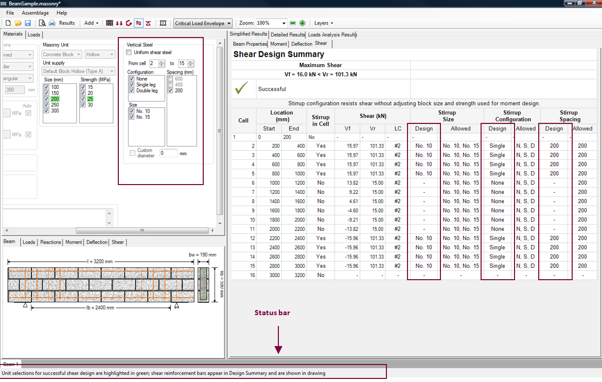
Figure 3‑41: Shear Design Step (Successful)
For the beam designed thus far, vertical steel (stirrups) are necessary to achieve a successful shear design. Notice, users cannot alter the vertical steel properties until the shear design step has begun.
Once the shear design step is performed, the Bearing Design button becomes red, indicating that at this stage it is possible to move on to the bearing design step. This is because the program provides default values for the bearing design step. Users, however, may wish to change the default properties.
Vertical Steel (Stirrups)
Upon the completion of a successful or unsuccessful shear design, users may wish to alter the design provided by the program. Under the Materials tab, the masonry unit properties previously entered or selected can be altered. The program automatically re-triggers the moment and deflection design step and the shear design step if any of the masonry unit selections are altered. To alter any other properties, users are required to return to the moment and deflection design step.
Users can now also change the vertical steel (stirrup) properties used in the design, as shown in Figure 3‑41. To alter the vertical reinforcement used along the length of the beam:
- Select the shear steel placement (uniform or non-uniform)
- Select the cell range
- Select the stirrup configuration (none, single leg, or double leg)
- Select the bar size
- Select the bar spacing
The ‘Uniform shear steel’ check-box is located at the top of the ‘Vertical Steel’ box, as can be seen in Figure 3‑42.
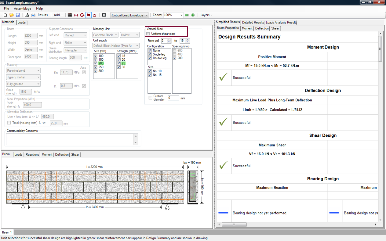
Figure 3‑42: Non-Uniform Placement of Shear Steel
The stirrups can be spaced at non-uniform (Figure 3‑43) or uniform intervals (Figure 3‑44) along the length of the beam.
|
Placed at Non-Uniform Intervals |
Placed at Uniform Intervals |
By default, the ‘Uniform shear steel’ check-box is checked-off. It is however, common that designers specify uniform stirrup spacing, because stirrups are frequently used as ties for the compression reinforcement.
*Note: Checking-on the ‘Uniform shear steel’ check-box guarantees that the stirrups are placed at uniform intervals. However, checking-off the ‘Uniform shear steel’ check-box does not necessarily result in shear steel placed at non-uniform intervals. Users can specify the shear steel placed in each cell along the length of the beam, and thus can generate a beam with uniform shear steel. The program itself may iterate through the shear steel possibilities and add shear steel on either end of the beam until a successful shear design has been achieved. This shear design may have evenly spaced stirrups along entire length of the beam as well. Refer to the section on Shear Design Strategy for more information on the shear design strategy employed in the beam module.
MASS™ numbers the cells from left to right along the length of the beam. The cell range, by default, includes the entire design length of the beam. To change the cell range, use the up or down arrows, or type the cell number into the textbox. This is shown in Figure 3‑45.
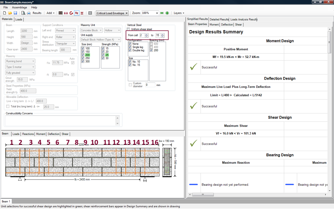
Figure 3‑45: Cell Range along Length of Beam
To alter the property of a specific cell (for example, cell 6); enter the cell number in the first textbox and the second textbox, as shown in Figure 3‑46. By default, the program attempts to design the beam with no stirrups. To allow a stirrup to be placed in cell 6, check-off the ‘None’ check-box. Observe that the specified stirrup is displayed in the beam drawing.
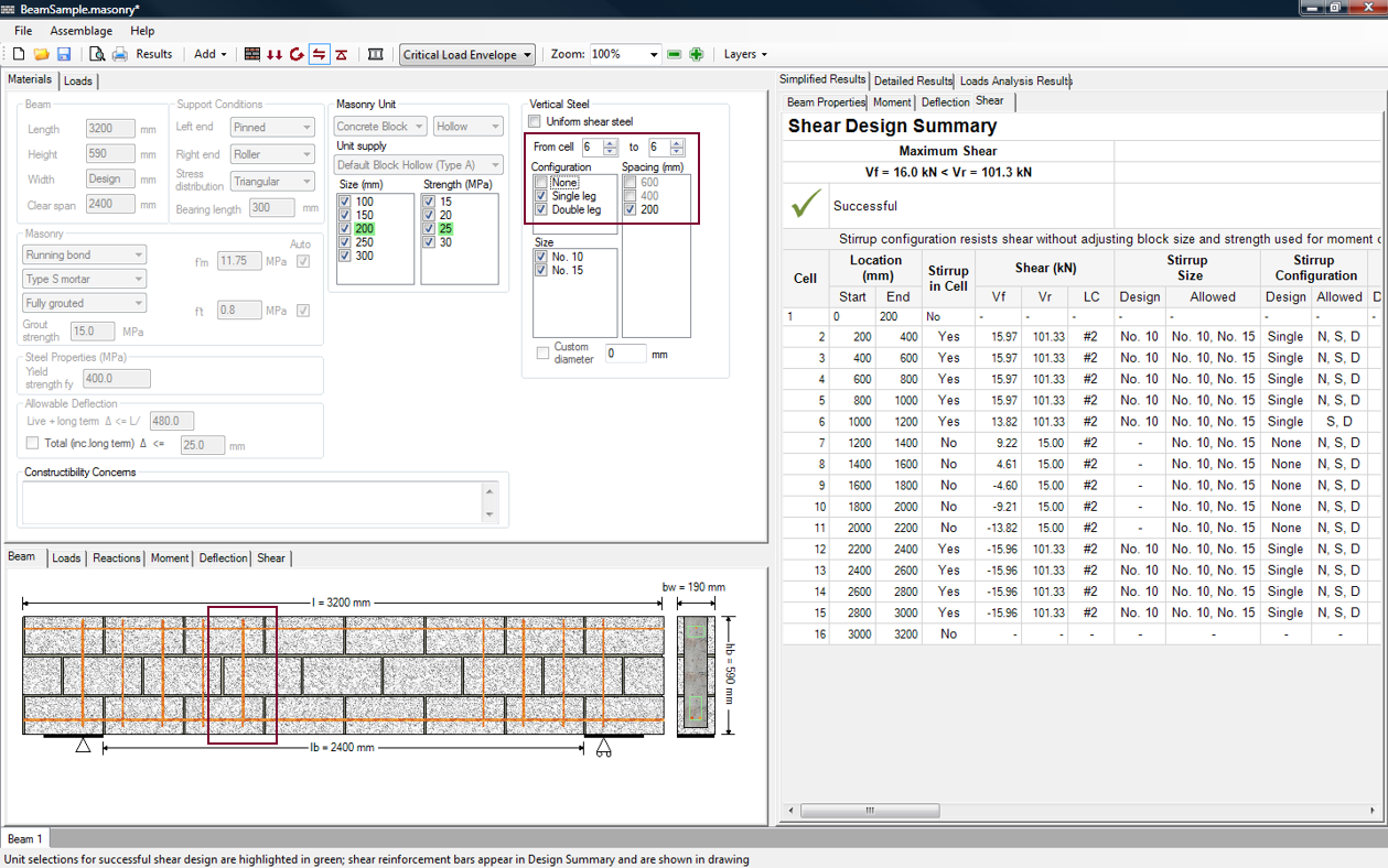
Figure 3‑46: Cell Range for a Specific Cell in the Beam
*Note: The vertical steel properties specified for a new cell range can override a previously entered vertical steel configuration if the new cell range overlaps with a previously specified cell range.
To select the bar size desired for the particular cell range chosen, check-on the desired ‘Size’ check-box. In the example shown in Figure 3‑47, both the No. 10 and No. 15 bar sizes are checked-on (by default). The beam is designed using No. 10 stirrups along the entire length of the beam, as shown in the Simplified Results → Shear tab. Notice, that for the shear design step (unlike the moment and deflection design step) the steel properties used in the design are not highlighted in green. This is because the stirrups used along the length of the beam may vary. Notice, also, that the design selections are reflected in the beam drawing in the bottom window.
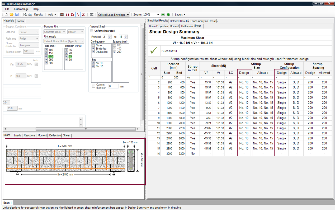
Figure 3‑47: Vertical Steel (Stirrup) Bar Sizes
Typical bar sizes used in stirrups are: No. 10, No. 15, No. 20, and No. 25. The No. 10, and No. 15 are the most commonly used. The No. 20, and No. 25 bars are restricted to the rare cases where the required bend radius fits the masonry unit. Bar sizes larger than No. 15 are difficult to work with (bending to form hooks) and to place inside the unit cells; hence, they are rarely used as stirrups. In MASS™, only bar sizes No. 10 and No. 15 are used by default. Non-standard and smaller bar sizes can be used. For a bar size not specified in the check-box list, check-on the ‘Custom diameter’ check-box, and enter the bar diameter into the neighbouring textbox.
A custom bar diameter of up to 25 mm can be entered, to account for the fact that in practice the stirrups can be placed inclined in the beam.
Bar sizes smaller than 6 mm are also not permitted. This is because stirrups can be used to tie horizontal compression steel to prevent the steel from buckling. The minimum bar size allowed by CSA S304-14: 11.2.6.4 is 6 mm. This limit is enforced whether or not users have tied the horizontal steel bars in the moment and deflection design step.
To select the bar spacing desired for the particular cell range chosen, check-on the desired ‘Spacing’ check-box, as shown in Figure 3‑47. Notice that in this case the only bar spacing available is 200 mm, and it is checked-on by default. According to CSA S304-14: 11.3.4.9, the maximum spacing allowed is the lesser of 600 mm or where, d is the distance to the centroid of the tension steel bars from the extreme compression face.
For the example shown in Figure 3‑48, the distance to the centroid is 507 mm. So the maximum spacing allowed is 507/2=253 mm. Because the stirrups must be placed within the cells (for single-wythe beams), the bar spacing options must be multiples of ½ the nominal block length. Thus, in this case, the only bar spacing available is 200 mm.
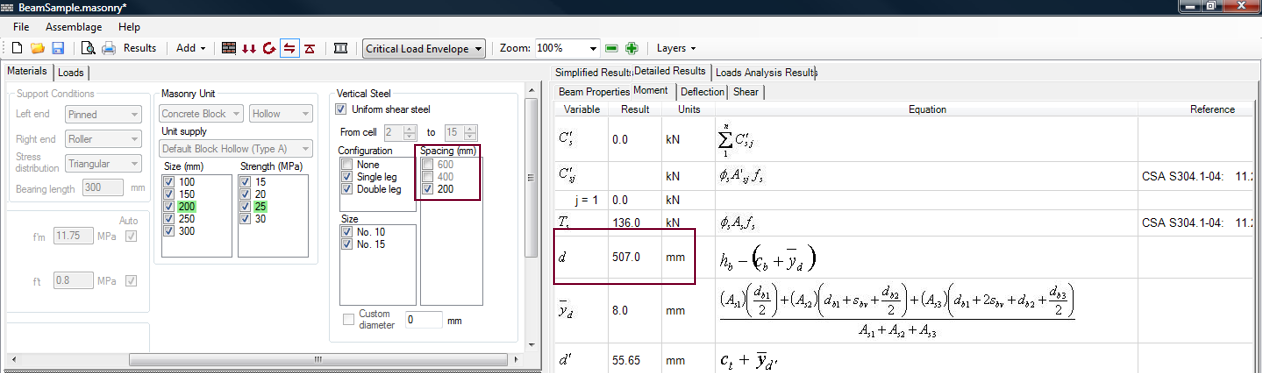
Figure 3‑48: Vertical Steel (Stirrup) Spacing
Additional limitations are placed on stirrup placement. For beam heights equal or less than 200 mm, vertical steel is not permitted by the program as it is very difficult to place stirrups in beam with that height. Stirrups are also not permitted for hollow concrete block, or brick beams of width equal or less than 100 mm; because the stirrups may not fit into the masonry unit (due to the stirrup loop placed around the horizontal steel).
The program is designed to update the Materials tab depending on the design parameters specified by the user. The ‘Vertical Steel’ box can be triggered by Clause 11.3.4.8. According to CSA S304-14: 11.3.4.8, the maximum spacing of stirrups allowed is the lesser of 600 mm or d/2; where, ‘d’ is the distance to the centroid of the tension steel bars from the extreme compression face.
For the sample beam with a height of 400 mm (two courses high) shown in
Figure 3‑49, stirrups cannot be added if d is less than 300mm. By default, MASS™ will place the primary tension steel below 300mm from the top of the beam but if the steel location is changed to 299mm, stirrups cannot be placed.
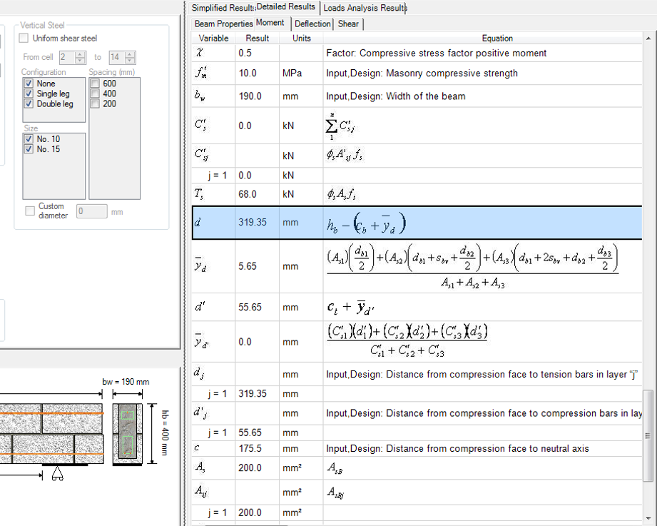
Figure 3‑49: Beam, No Stirrup Spacing Options
The distance to the centroid is 319.35 mm. The maximum spacing is then the least of 600mm and:
d/2=319.35/2=157.68 mm
This d/2 is smaller than 200 mm (the spacing between neighbouring cells). Therefore, there is no satisfactory stirrup spacing, and as a result, the whole ‘Vertical Steel’ box is greyed out. In other words, the maximum spacing permitted is smaller than the spacing the stirrups could be placed at.
*Note: Since the CSA Standards were updated to the 2014 edition, it has become much easier to place stirrups in beams thanks to a change in CSA S304-14: 11.3.9 which added a sentence allowing designers to place stirrups at 200mm spacing even if d/2 is less than 200mm as long as d is still greater than 300mm.
Consider changing the height of the beam to 600 mm, such that it is three courses high. For the sample beam with a height of 600 mm (three courses high) shown in Figure 3‑50.
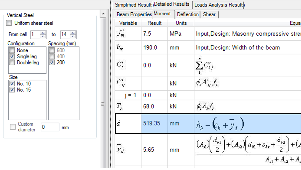
Figure 3‑50: Sample Beam, Stirrup Spacing of 200 mm Permitted
The distance to the centroid is 319.35 mm. The maximum spacing is then the least of 600mm and:
d/2=519.34/2=259.67 mm
This d/2 is larger than 200 mm (the spacing between neighbouring cells). Therefore, a stirrup spacing of 259.67mm or less can be used. For this reason, the ‘Vertical Steel’ box is now enabled, as shown in
Figure 3‑50. Notice however, that only the 200 mm checkbox is available. For beam designs with d/2 values that equal or exceed 600 mm, all three stirrup spacing options (200, 400, 600 mm are available).
To design a beam with no stirrups, select the entire cell range (for example cells 1-16 in Figure 3‑46), and check-off the ‘Single leg’ and ‘Double leg’ check-boxes. Alternatively, check-on the ‘Uniform shear steel’ check-box, and then check-off the ‘Single leg’ and ‘Double leg’ check-boxes. The ‘Size’ check-boxes and the ‘Spacing’ check-boxes in this case are grey to indicate they are disabled.
Shear Design Step: Unsuccessful Design
If all the possible vertical steel loops iterations are exhausted in the shear design step, the program returns to the moment and deflection design, and iterates through the horizontal steel and masonry unit selections (block size/strength).
*Note: MASS™ does not perform special analysis specific to deep shear span design (CSA S304-14: 11.3.6). Sections of a beam can be considered to be deep shear spans when: the effective depth of the reinforcement, d, is less than 400 mm, and the distance from the point of zero shear to the face of the support is less than 2d; or, a load causing more than 50% of the shear is located at a distance less than 2d from the face of the support.
*Note: MASS™ will still design deep shear spans. However, the results will be very conservative so it is recommended that the user performs their own more rigorous analysis. CSA S304-14: 11.3.6.2 was rewritten to allow the same analysis for deep shear spans as would be used for beams which are not deep shear spans.
For more information on the shear design strategy used in the beam module, refer to the section on Shear Design Strategy.
Upon the completion of the shear design step, users can proceed to the bearing design step.
Bearing Design
Bearing Design is the fifth step in developing a beam design. To run the bearing design step click on the Bearing Design button shown in Figure 3‑51.

Figure 3‑51: Bearing Design Step
Notice that when performing the bearing design step, the Bearing Design button is outlined in blue. During this design step, the beam is designed to resist the maximum factored support reaction, and the maximum factored point load (using the bearing length and stress distribution provided by users). At the end supports of beams and where concentrated loads are applied, high local compressive stresses are developed. The masonry at these locations must be able to handle the compressive stresses. CSA S304-14: 7.14 indicates the design provisions for bearing resistance under concentrated loads.
Bearing Design: Successful Design
The successful design produced after performing the bearing design step is shown in Figure 3‑52. In this case, the program does not provide a bearing design for any point loads because none have been placed along the length of the beam.
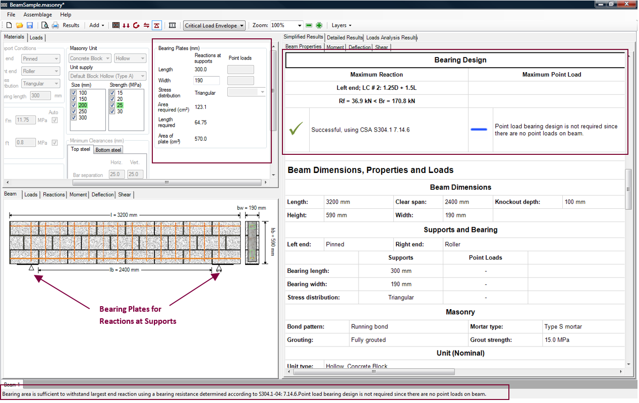
Figure 3‑52: Bearing Design (Successful)
Once again, the status bar at the bottom of the page informs users whether or not a successful design is found. The tab provides the length and width of the bearing plates used at the supports and at the location of any applied vertical point loads. The Simplified Results Beam Properties tab provides summarized bearing design results.
There is no Bearing tab used to display simplified or detailed results.
For more information on reading the simplified results provided in the Beam Properties tab refer to the section on Simplified Results.
Bearing Plates
Upon the completion of a successful or unsuccessful bearing design, users may wish to alter the design provided by the program. Under the Materials tab, the bearing plate properties previously entered or selected can be altered. The program automatically re-triggers the moment and deflection design step and the shear design step if any of the masonry unit selections are altered.
For bearing plate(s) at the supports(s), during the bearing design step, users can only change the bearing plate width, shown in Figure 3‑53. To change the bearing length or stress distribution, users are required to return to the assemblage configuration design step. The lower limit for bearing width (for both reactions at supports, and point loads) is 50 mm (imposed by the program not by the CSA Standards). The upper limit is the width of the beam after design.
Based on the bearing plate width and length, and the stress distribution entered/selected by users, the area of the design bearing plate is provided. Although the bearing area can be different for each support, this version of the program uses the maximum reaction at the supports to perform the bearing design, and assigns the same bearing area to both supports. The minimum bearing plate area and minimum bearing plate length are also provided.
For bearing plates at any applicable vertical point load locations, during the bearing design step, users can change the bearing plate length, width, and the stress distribution.
Based on the bearing plate width and length, and the stress distribution entered/selected by users, the area of the design bearing plate is provided. Although the bearing area can be different for each point load, this version of the program uses the maximum point load along the beam to perform the bearing design, and assigns the same bearing area to all point loads. The minimum bearing plate area and minimum bearing plate length are also provided.
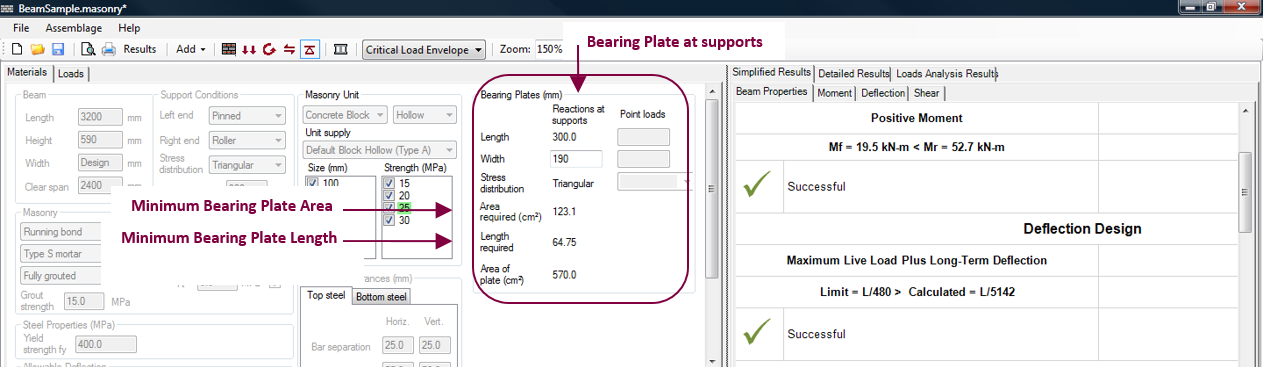
Figure 3‑53: Altering Bearing Plate Properties
Once again, upon the completion of a successful or failed design, users may wish to alter the design provided by the program. To alter any assemblage properties or horizontal steel properties:
- Return to the moment design step by clicking on the Moment and Deflection Design button:
 .
. - Under the Materials tab, change the material properties previously entered or selected. The program automatically re-triggers the moment and deflection design step if any of the check-box material selections are altered. For new values that are entered into a textbox press on the keyboard to re-trigger the moment design.
- Complete the shear design step by clicking on the Shear Design button
 in the toolbar once more.
 - Complete the bearing design step by clicking on the Bearing Design button
 in the toolbar once more.
Upon the completion of the bearing design step, the beam design is complete.
Warning: Detailing work is left up to the designer. MASS does not determine splice lengths, development length, hooks, etc.
Continue Reading: A Complete Beam Design