

Latest Software Blog Posts
Conventional Construction Comprehensive Analysis Example
Are you curious about how MASS conducts a detailed analysis of Conventional Construction walls through its Comprehensive Analysis method? Don’t worry, we’ve got you covered!
MASS evaluates the axial load applied to a Conventional Construction wall with a seismic hazard index exceeding 0.35, ensuring it remains less than the allowable limit of 0.1f’m. In MASS v4.2, users now have the option to conduct a comprehensive analysis. This analytical enhancement is designed to effectively address scenarios where the axial load surpasses 0.1f’m. More information about the comprehensive analysis is covered in this article.
Disclaimer: This post is exclusively intended to provide insight into the approach taken by the MASS design software in implementing a comprehensive analysis for Conventional Construction shear walls. It is up to the professional discretion of the designer to input an appropriate layout, boundary and loading conditions, interpret the results, and determine how they should be incorporated into their designs. As per the end user license agreement (and also recommended within PEO’s guidelines for using engineering software), a tool cannot be considered competent and reliance on a tool does not relieve the user of responsibility.
Determining the appropriate comprehensive analysis method depends on whether the wall in question is squat or not. We will go over 2 examples, one of a squat wall and another of a non-squat wall.
Squat Wall
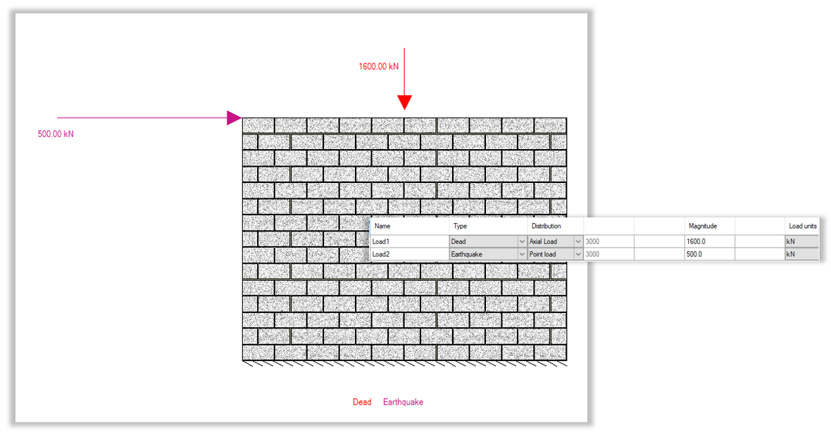
Consider the following squat shear wall, designed using a 20cm, 20 MPa unit with vertical 20M bars placed at a spacing of 800 mm in a wall that is 4000 mm long and 3000 mm high (hw/lw < 1). The importance category is normal.
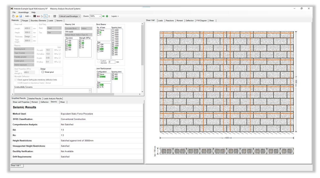
A fully-grouted wall with 6-20M vertical bars, 4-20M horizontal bond beams and 3.66 mm 2-wire joint reinforcement every course can be seen in the screenshot below:
First we must determine whether or not the comprehensive analysis is required. The axial load limit can be calculated as follows:
0.1*Ae*f’m
= 0.1*(190*4000)*10
= 760 kN
Therefore, since the applied axial load of 1600 kN is greater then the axial load limit of 760 kN, it is feasible to apply the comprehensive analysis for the design of this wall.
We will go through this design example following the design requirements listed out in Table 1 covered in this article.
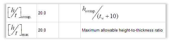
The first requirement is that the unsupported height of the wall shall be such that the height-to-thickness ratio (hw/(t+10)), of the wall in the compression zone is less than 20 (Clause 16.7.4, CSA S304). For this wall:
(hw/(t+10))
= 3000 / (190 + 10)
= 15
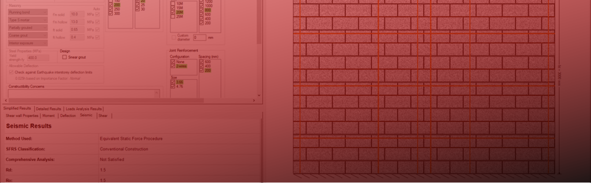
This check can be found in MASS under the Seismic Detailed Results tab as seen in the image below:
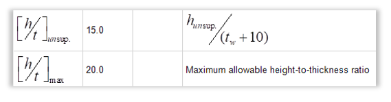
Therefore the height-to-thickness ratio of this wall is less than 20 and we can proceed with the Comprehensive Analysis.
The second requirement is that the horizontal and vertical reinforcement ratios shall not be less than that determined using the following equations (CSA 16.7.5, CSA S304):
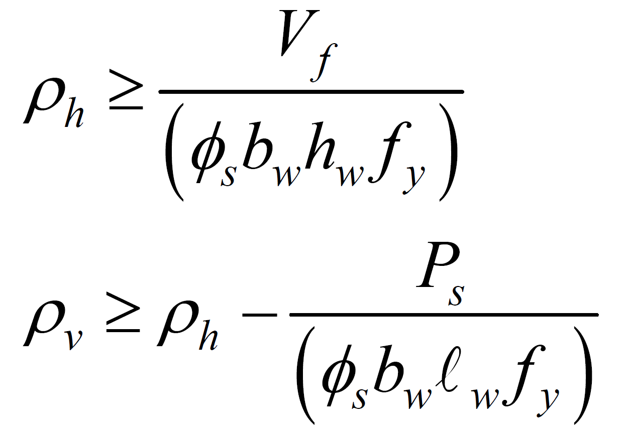
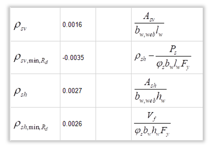
First we will solve for horizontal reinforcement ratio. This is calculated based on the Area of Reinforcement in the horizontal direction. For this wall we have a bond beam with 1-20M rebar (300 mm2) spaced every 800 mm for a total of 4 bond beams and joint reinforcement that consists of 3.66mm 2-wire joint reinforcement (21 mm2) every 200 mm.
ρh = Ash/(bw,web*hw)
ρh = (300*4 + 21*(3000/200)) / (190*3000)
ρh = 0.0027
The above value of 0.0027 must be greater than:
Vf/(Φs*bw*hw*fy)
= (500*1000) / (0.85*190*3000*400)
= 0.0026
Therefore, there is an adequate amount of horizontal reinforcement in this wall to pass the horizontal reinforcement ratio check of the Comprehensive Analysis.
We can now do the check for the vertical reinforcement ratio. This is calculated based on the Area of Reinforcement in the vertical direction. As seen in the screenshot above we have 6-15M vertical rebars (200 mm2) in this wall:
ρv = Asv/(bw,web*lw)
ρv = (200*6) / (190*4000)
ρv = 0.0016
The above value of 0.0016 must be greater than:
ρh – Ps/(Φs*bw*lw*fy)
= 0.0027 – (1600*1000) / (0.85*190*4000*400)
= -0.0035
Therefore, there is an adequate amount of vertical reinforcement in this wall to pass the vertical reinforcement ratio check of the Comprehensive Analysis. All other minimum steel requirements in Clause 10 and 16 from the CSA S304 still must be satisfied for this design.
These checks can be found in MASS under the Seismic Detailed Results tab as seen below:
Following Table 1 from this article, the horizontal and vertical reinforcement ratios have both been checked against the limits specified. Based on these checks we can see that there is an adequate amount of horizontal and vertical steel in this wall and that the wall can be seen to preform adequately as per the comprehensive analysis even though the axial load exceeds the axial load limit of 0.1f’m as per Clause 16.5.3.
Non-Squat Wall
Consider the following non-squat shear wall, designed using a 25cm, 15 MPa unit with vertical 15M bars placed at a spacing of 400 mm that is 5000 mm long and 5000 mm high (hw/lw ≥ 1). The importance category is normal.
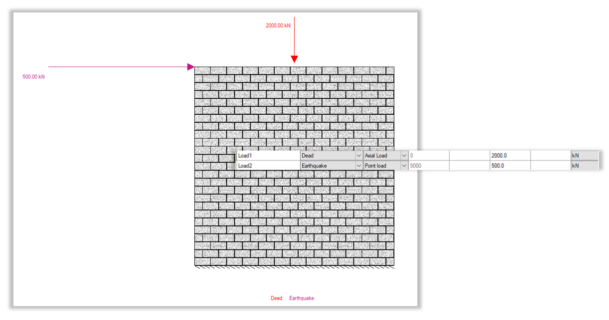
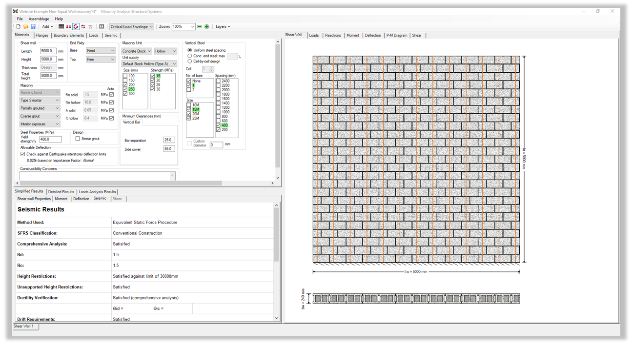
A fully-grouted wall with 15M vertical bars every 400 mm and 4.76 mm 2-wire joint reinforcement every course can be seen in the screenshot below:
First we must determine whether or not the comprehensive analysis is required. The axial load limit can be calculated as follows:
0.1*Ae*f’m
= 0.1*(240*5000)*7.5
= 900 kN
Therefore, since the applied axial load of 2000 kN is greater then the axial load limit of 900 kN, it is feasible to apply the comprehensive analysis for the design of this wall.
We will go through this design example following the design requirements listed out in Table 2 covered in this article.
The first requirement is that the unsupported height of the wall in the plastic hinge shall be such that the height-to-thickness ratio (hw/(t+10)), of the wall in the compression zone is less than 20. Exclusions are also permitted for walls with thicker sections at the end, neutral axis depths of a certain limit and walls with flanges per Clause 16.8.3.2-16.8.3.4 in CSA S304. For this wall:
(hw/(t+10))
= 5000 / (240 + 10)
= 20
This check can be found in MASS under the Seismic Detailed Results tab as seen in the image below:
Therefore the height-to-thickness ratio of this wall is less than or equal to 20 and we can proceed with the Comprehensive Analysis.
The next requirement is to ensure that the portion of the wall that is in the plastic hinge region is fully grouted. For a single storey wall, it is always best to consider the whole wall to be in the plastic hinge region, for a multi-storey shear wall the plastic hinge region can be calculated. MASS does this calculation and ensures that only the portion of the wall in the plastic hinge region is fully grouted when doing a comprehensive analysis, unless otherwise specified. In addition to this, the length of the wall, lw, shall be taken as the extent of the plastic hinge region, hp.
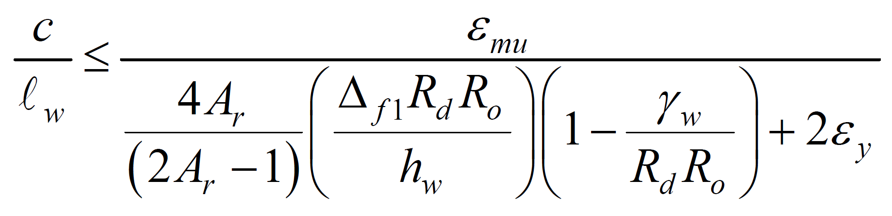
Lastly, the inelastic rotational demands and maximum axial load for a Conventional Construction non-squat shear wall are deemed to be satisfied by the following limit per Clause 16.8.8.4 in CSA S304:
First we will determine what the c/lw ratio of this wall is. Calculations for the neutral axis depth are not shown and are assumed to be known by the user (c = 2983.3 mm). The neutral axis depth of the wall can be found in Moment tab in MASS:
c/lw
= 2983.3/5000
= 0.5967
Next we can solve for the limit. For this limit we will assume that the user can obtain all the values for the variables in this equation based on Table 2. Values for each variable are listed below before plugging them into the equation:
εmu = 0.003
Ar = 1
Δf1 = 4.1 mm
Rd = 1.5
Ro = 1.5
γw = 1.94
εy = 0.002
εmu / [(4Ar/(2Ar-1))*(Δf1RdRo/hw)*(1-γw/(RdRo))+2εy]
= 0.003 / [(4(1)/(2(1) – 1))*((4.1*1.5*1.5)/5000)*(1 – 1.94/(1.5*1.5)) + 2*0.002]
= 0.5973
These checks can be found in MASS under the Seismic Detailed Results tab as seen below:
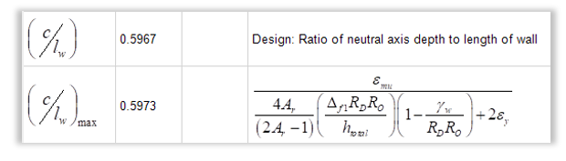
Following Table 2 from this article, the c/lw ratio is checked against the limit specified. Based on these checks the inelastic rotational demands and maximum axial load for a Conventional Construction non-squat shear wall are deemed to be satisfied as per the comprehensive analysis even though the axial load exceeds the axial load limit of 0.1f’m as per Clause 16.5.3.
Concluding Thoughts
The Comprehensive Analysis for the design of Conventional Construction Shear walls is included in the next available technical release as part of MASS Version 4.2.
If you see a mistake or have any questions regarding this design example please do not hesitate to contact MASS technical support.