

User Interface Overview
User Interface Overview
Upon opening a .Masonry14 file, the default assemblage is a beam. Figure 2-1: Overview of tabs- provides some of the more important tools and features available in MASS™ for a beam assemblage. The majority of these features are also common to the wall and shear wall modules.
Toolbars
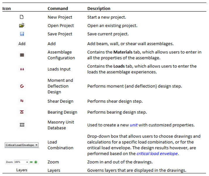
Table 2-1: Overview of toolbar provides a list and brief description of the buttons available in the main MASS™ toolbar.
Table 2-1: Overview of toolbar
Tabs
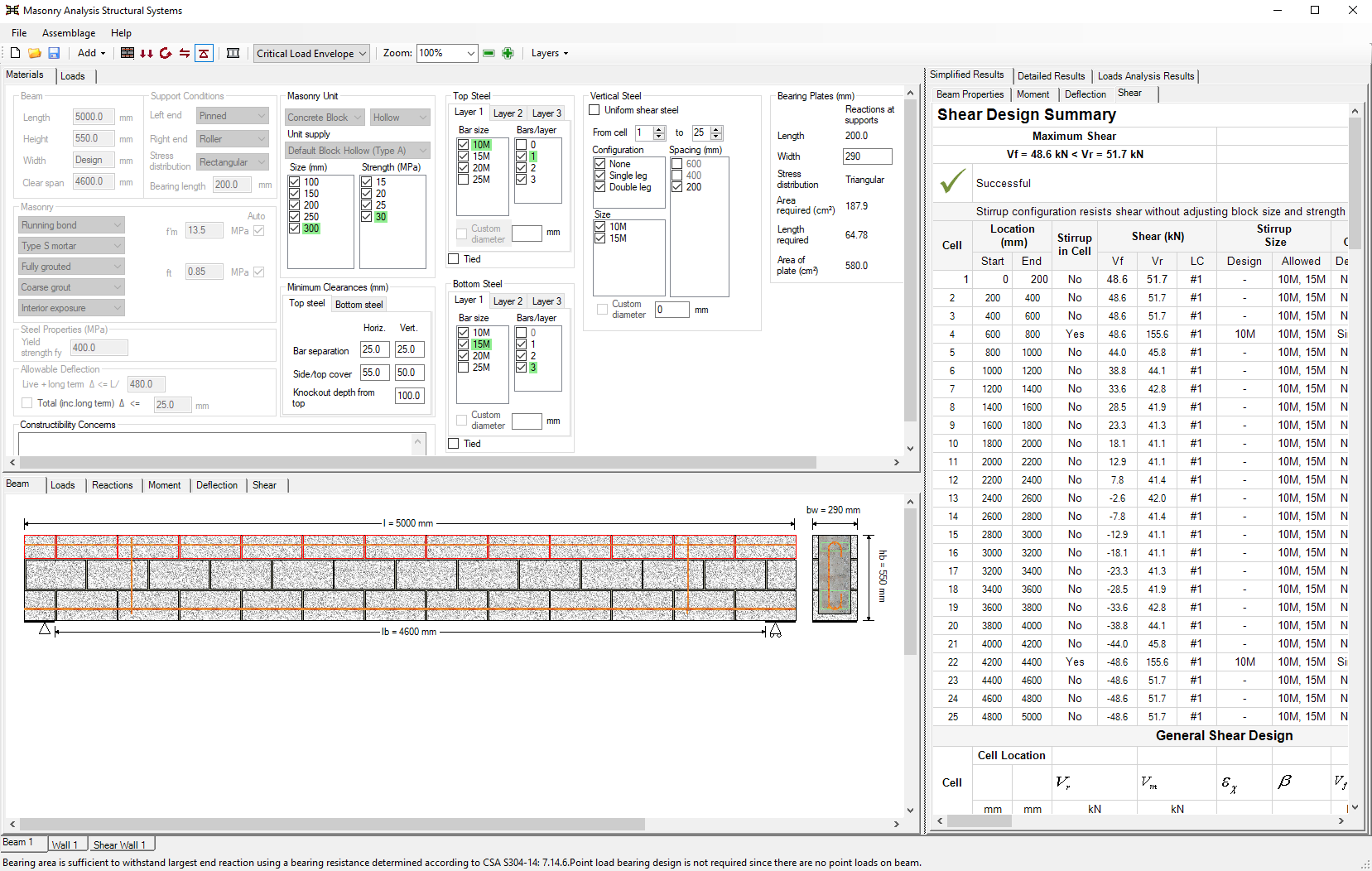
Figure 2-1: Overview of tabs- provides a brief overview of some of the main features of the program.
Overview of tabs
Materials: Contains the Materials tab, which allows users to enter in all the properties of the assemblage.
Loads: Allows users to applied loads and moments to the assemblage.
Beam, Loads, Reactions, Moment, Shear, Deflection: Allows users to view the assemblage, the loads applied, the reactions, as well as the moment, shear, and deflection of an assemblage with respect to its centroid. MASS™ uses deflection limits to carry out the deflection design of beams and walls. The limit for beam deflection is L/480, CSA S304.1-14: 11.4.5, or a maximum total deflection input by users; the limit for out-of-plane wall deflection varies from span/180 to span/360, CSA S304.1-14: 10.14.3, or a maximum total deflection input by users. The program includes the effects of slenderness, deflection due to deflection, for deflection calculations of out-of-plane walls.
Simplified Results: Provides a summary of the design results at each design step.
Detailed Results: Provides detailed intermediate design calculations.
Load Analysis Results: Provides the internal forces along the assemblage in the form of data tables.
Status bar: Updates users on the progress of the design.
Beam 1: Tab that allows for the design of a beam.
Wall 1: Tab that allows for the design of an out-of-plane wall.
Shear wall 1: Tab that allows for the design of a shear wall.
Windows and Margins
The three main windows in the program are: the input window, the drawing window, and the results window, as shown in Figure 2-2: Input Window, Drawings Window, and Results Window-.
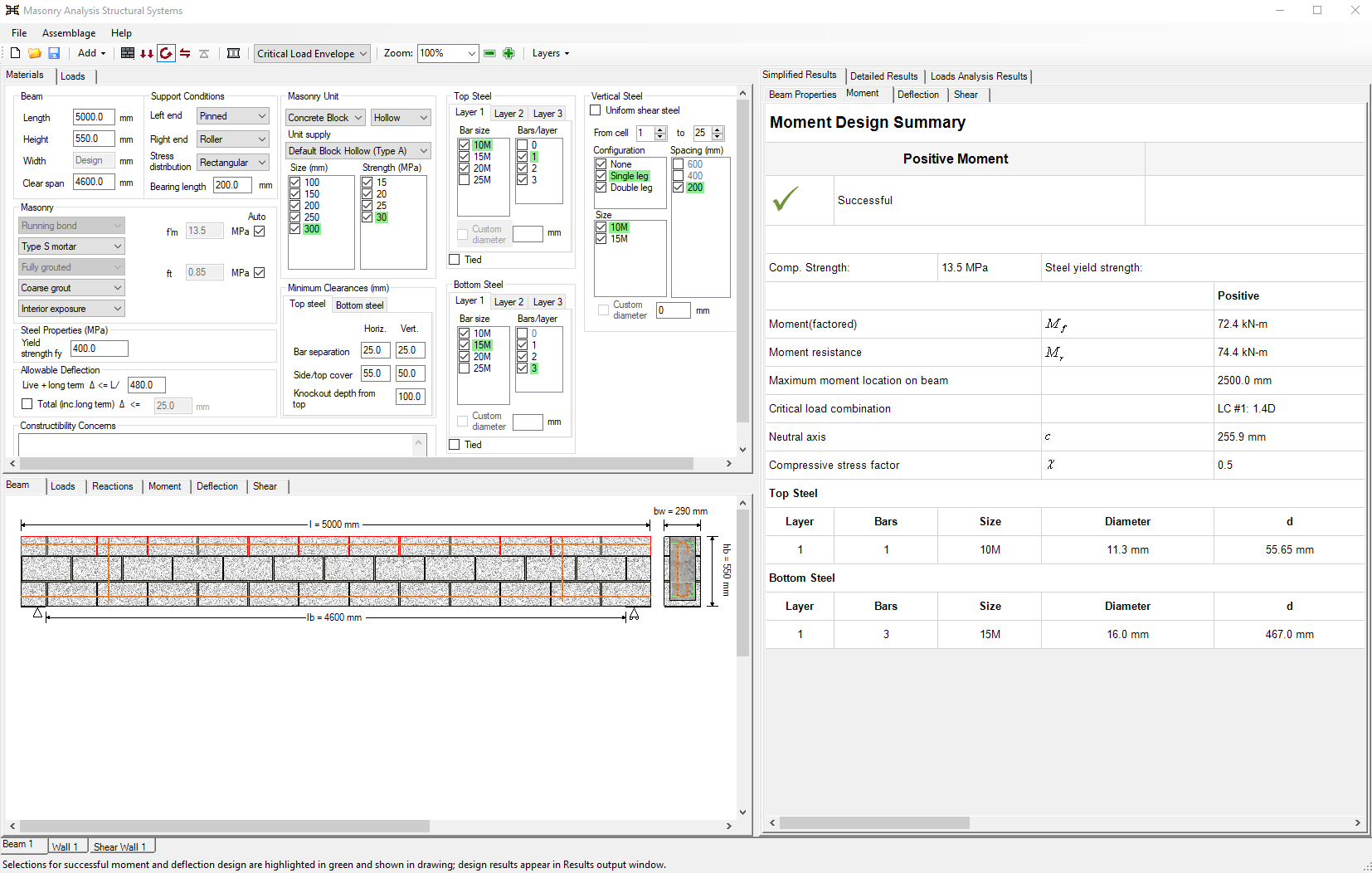 Figure 2-2: Input Window, Drawings Window, and Results Window
Depending on the assemblages, the location of these windows may be rearranged. All window margins within the program are adjustable.
To adjust a window size:
- Place the mouse cursor over the margin to be adjusted. The mouse pointer
 changes from to
  vertical resize or
  horizontal resize.
- Click and drag the margin to the desired location.
The outer most edges of the windows are also adjustable; however, these resize the entire program window.
Continue Reading: Design Steps