Latest Software Blog Posts
Notification: Seismic Shear Forces Amplification Change for Elements Above Critical Section
The storey-by-storey design approach currently in MASS can excessively amplify shear forces beyond expected results
In cases where a bug or other issue is found in the MASS software, announcements are posted on the software’s known bugs page, as well as on this page here. It is always encouraged that suspected bugs are submitted by engineers through technical support.
Disclaimer: This post is exclusively intended to provide insight into the approach taken by the MASS design software in interpreting a CSA S304-14 code compliant seismic design. It is up to the professional discretion of the designer to input an appropriate layout, boundary and loading conditions, interpret the results, and determine how they should be incorporated into their designs. As per the end user license agreement (and also recommended within PEO’s guidelines for using engineering software), a tool cannot be considered competent and reliance on a tool does not relieve the user of responsibility.
This post explains an issue with the implementation of the CSA S340-14 design requirement. Internally within MASS technical discussions, it was decided that the interpretation was unduly punitive to shear wall designs as summarized and explained in further detail below.
Summary
When MASS amplifies in-plane shear forces resulting from a seismic load combination, it first distributes the unfactored loads to each shear wall element where all analysis and design calculations are permitted. This is how the software is able to report moment and shear resistance results for each story with full output available, even though the critical section at the base of the wall may have been the only element necessary.
When MASS performs seismic amplification, it is done for each floor with no consideration of what is above or beneath it. For shear wall elements above the base of the structure, it is possible that MASS will excessively amplify shear forces beyond what is required.
The video below goes through the process and reviews the shear amplification rationale to explain the current software results, as well as what could be done differently to avoid such extreme, punitive jumps in factored shear going up the height of the wall.
This change is a result of how the shear amplification requirements are interpreted within MASS, where the degree of amplification at the critical section within the critical element can be used for all other elements of the shear wall.
Background Information
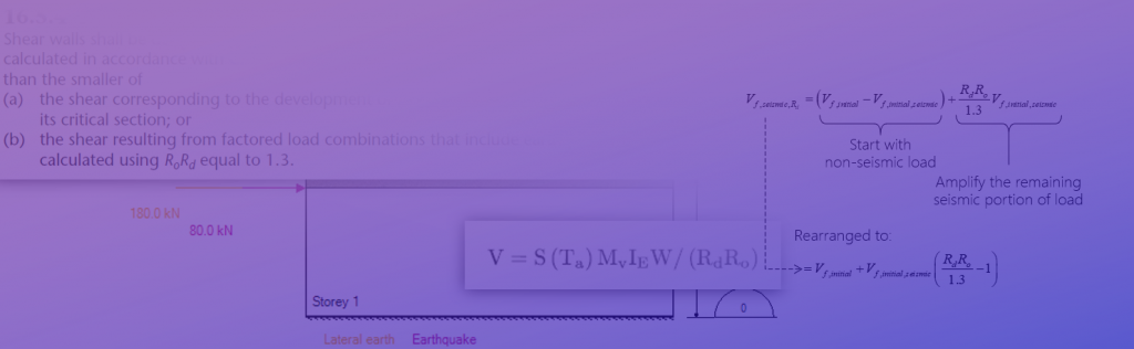
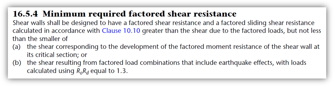
A full explanation of the process used to scale up earthquake forces for the purposes of in-plane shear design is covered in further detail here. All references are taken from CSA S304-14 unless otherwise stated. The relevant expression for conventional construction shear walls is shown below:
Note: there are different versions of this requirement depending on the ductility of the SFRS being designed. They are explained further here.
This subsection provides some context to these requirements to better understand how a different interpretation can impact design results.
Ensuring Flexural Failure
Part (a) of this clause refers to the critical section which MASS defines internally as the location of the wall where the factored moment is closest to the moment resistance envelope as a percentage or ratio. For shear wall designs, that are not smaller elements within a larger elevation, such as a narrow pier between openings, the critical section will pretty much always be at the base of the wall.
As referenced earlier, the software also takes the approach of modelling each storey of the shear wall as it’s own shear wall element, with distributed loads applied to generate a design with detailed results available for every location along the height. Since this analysis and design work is done at the individual element level, a seismic shear amplification is performed within each element’s design process, and as a result, MASS currently uses varying degrees of shear force amplification for each storey.
Not Overestimating Ductility
Part (b) of this requirement is essentially an upper limit based on shear wall SFRS ductility category. While there is no explicit mention of critical section in part (b), it is used to compare with part (a) meaning that functionally, the critical shear wall element is the only place this must be checked as ductility designations cannot be changed within a single shear wall (or for different masonry elements in a SFRS).
Once again, this is covered in further detail on the main shear amplification series of posts (linked here). The references for other SFRS ductility selections is also available within those posts.
The Change of Interpretation
The interpretation change for where the critical section is identified for each shear wall element will potentially have a very large impact on in-plane shear design for elements above the bottom storey, as it can be argued that even for those elements, the critical section to be considered is still at the base of the overall multi-storey shear wall.
While this certainly could be performed on a element-by-element basis, MASS technical support took the interpretation that it was needlessly conservative to be increasing cross section properties for elements that otherwise should not be considered critical. If the design is governed by the axial load, bending moment, and shear force at the base of the wall, this is the location at which the seismic shear amplification should be determined.
The example shown below illustrates the differences between the two interpretations and the results on final design loads.
Determining shear amplification based on each storey’s own local critical section often results in a varying degree of shear force increases for different locations along the height of the wall. Amplifying all shear wall elements based on a single critical section will affect all designs proportionally (see example below for details), but likely reduce amplification above the bottom storey.
Note that MASS currently (as of publication) takes the former approach whereas the software will be updated to adopt the latter. The example below breaks down the numeric process of getting each result.
Design Example
This subsection will step through the calculation process of how in-plane shear forces are amplified, showing the differences between the current conservative approach and the to-be-released updated approach. It is intended to be as simple as possible to illustrate the different approaches.
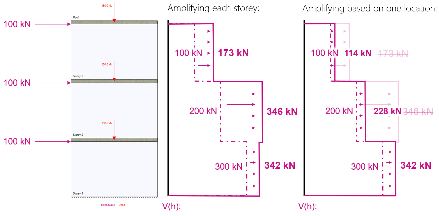
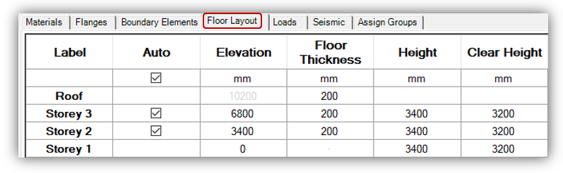
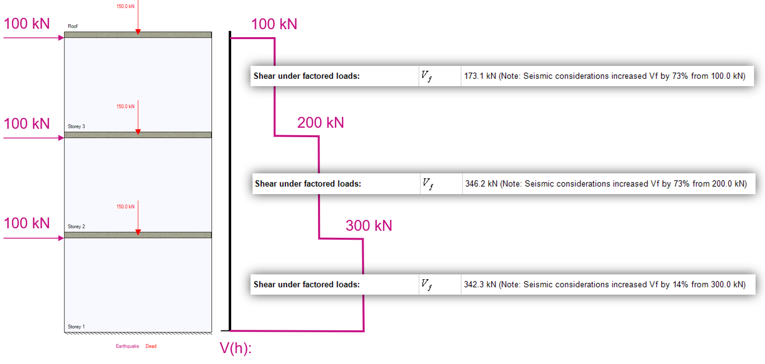
A three storey shear wall is 10.2 m tall with floors evenly spaced.
The wall is loaded with 100 kN lateral point loads at each floor, as well as 150 kN axial dead loads.
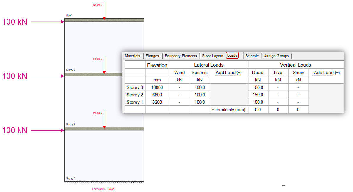
All other settings including self-weight and importance category are left at their default selections. Under the seismic tab, Conventional Construction is selected for ductility with other required inputs entered in.
Under the seismic input tab, the following inputs were used for this example:
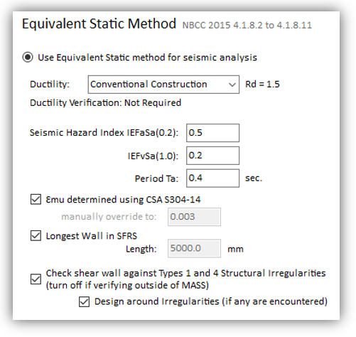
The most important selection is the Ductility selection as it will directly impact the result in this example related in in-plane shear force amplification. Other inputs either trigger minimum steel area checks or other error messages.
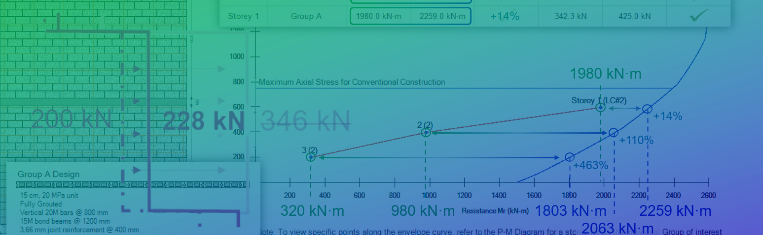
The shear wall is then designed using a 15 cm, 20 MPa unit with vertical 20M bars spaced at 800 mm, 3.66mm joint reinforcement every second course (spaced vertically at 400mm), and 15M bond beams every 1200 mm spaced vertically from the top of each floor.
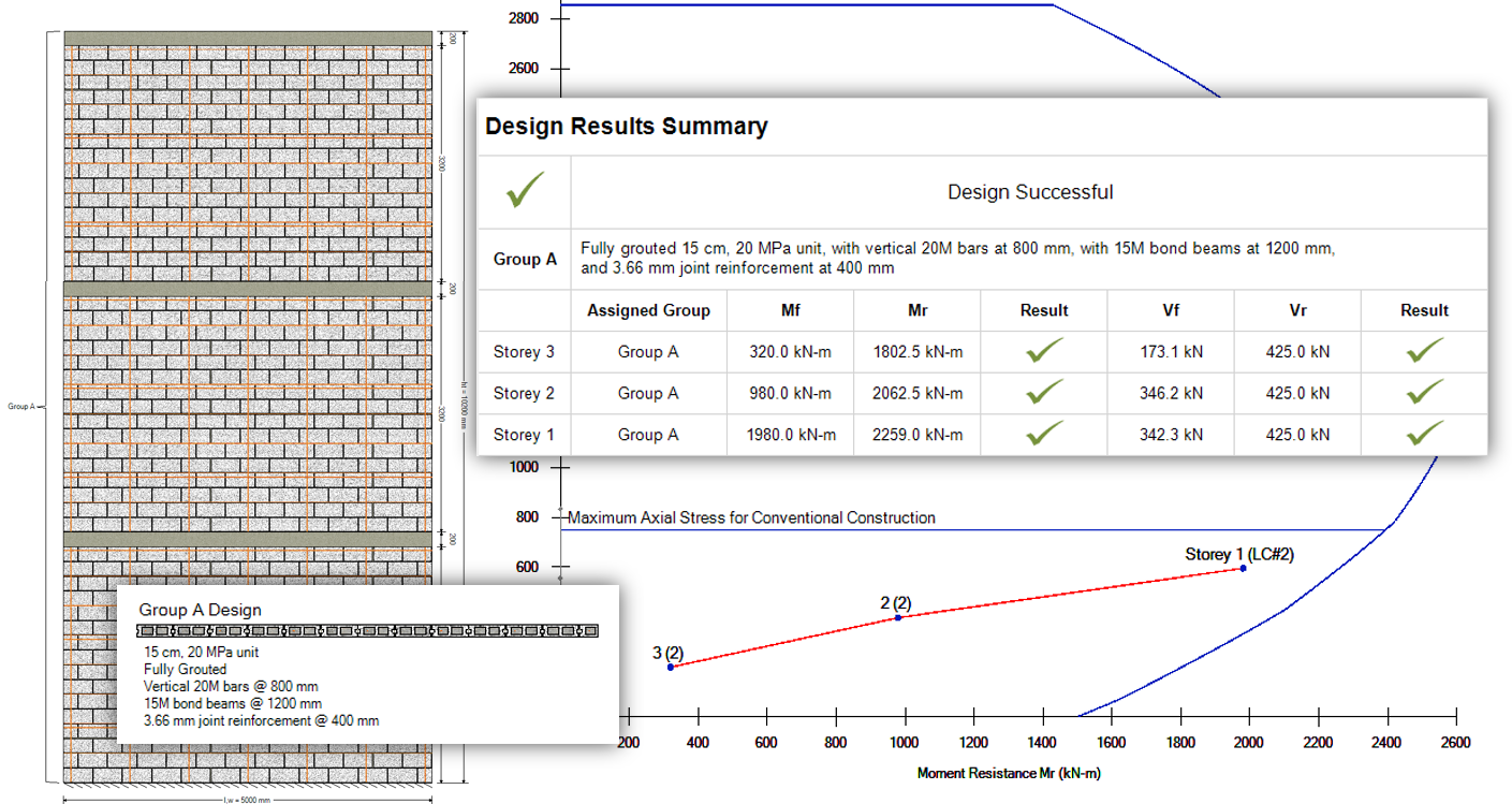
Looking further into the results, note the factored shear designed for at each floor level. Storey 2 is designed to resist a larger factored in-plane shear force compared to the base of the wall which experiences a 50% larger unfactored seismic shear.
 As explained in the background information section, as well as the series of posts here, there are two methods in which to amplify seismic shear forces. The former is based on the degree of flexural overstrength. The figure below shows the factored moment and corresponding resistance at that storey’s axial load:
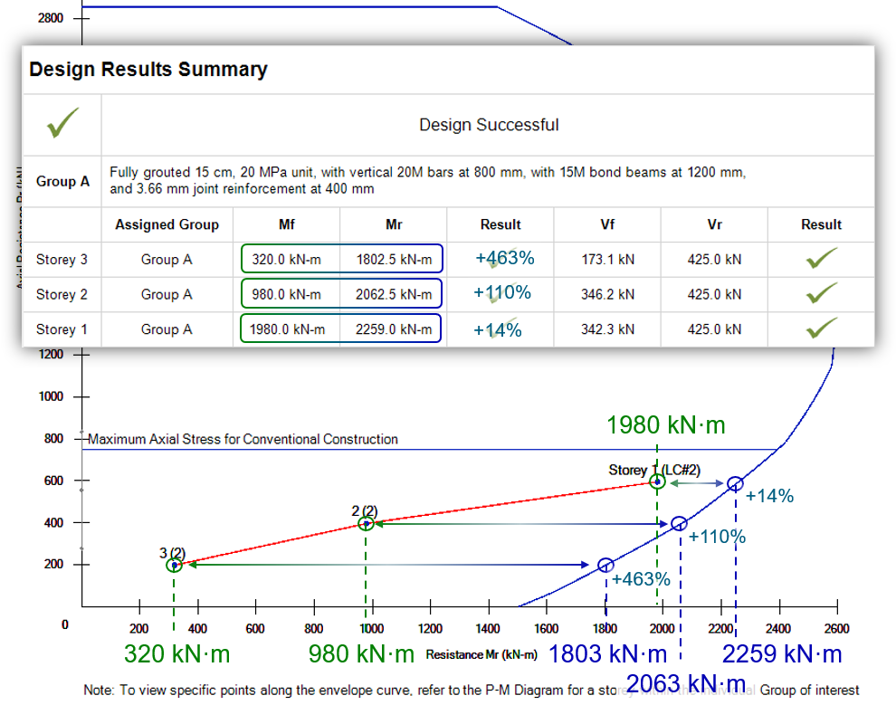
Since the shear wall is designed for the critical section at the base, it is expected that the lowest degree of flexural overdesign will be observed at that location. That being said, this approach also is designing each element being loaded to flexure, rather than just at the critical element at the base of the wall. This is where the difference in shear amplification comes from and will be circled back to further down.
After the flexural overdesign has been considered, the degree of potential shear amplification is compared to what the applied seismic loading would have been had RdRo = 1.3 to not overestimate potential ductility performance. In the case of Conventional Construction shear walls, this increases seismic loading by over 73% which can be thought of as the upper limit to degree at which shear forces can be amplified for any given element.
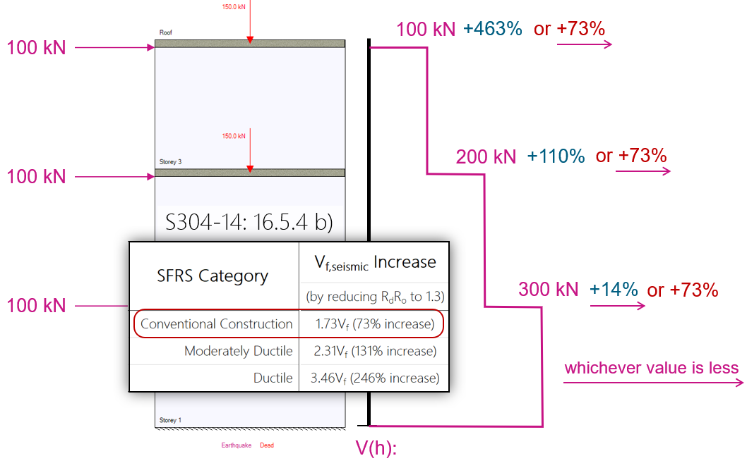
Again, since the flexural overdesign is evaluated at each floor, different degrees of amplification are seen, resulting in cases where shear is amplified to a larger magnitude further up the wall compared to the amplification at the critical section at the base. This is also seen in the following shear diagram (current as of Version 4.0 within MASS):
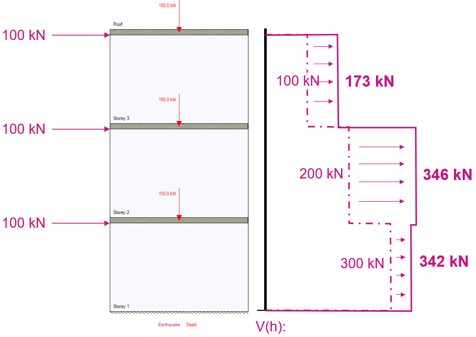
It is the opinion of the MASS technical support team that the approach and resulting amplification shown above is excessively conservative and there is no need to evaluate flexural overdesign at each element of a shear wall. The entire multi-storey assemblage can itself be classified as a single, continuous shear wall and as a result, this can be evaluated solely at the base.
Looking at the bending moment diagram resulting from the unfactored seismic loads, it should come as no surprise that the base of the wall is critical. When comparing the moment resistance to factored moment at the critical section, it is proposed that only the base be considered with no additional regard for the storeys resting above.
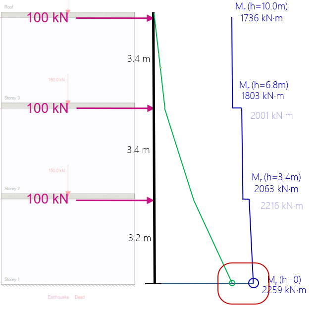
In this case, as was seen earlier on the interaction diagram, there is a difference between the base storey’s moment resistance and the seismic factored moment given the axial loading on the critical section. By scaling up all loads by this ratio, the wall would experience bending at the base equal to its resistance.
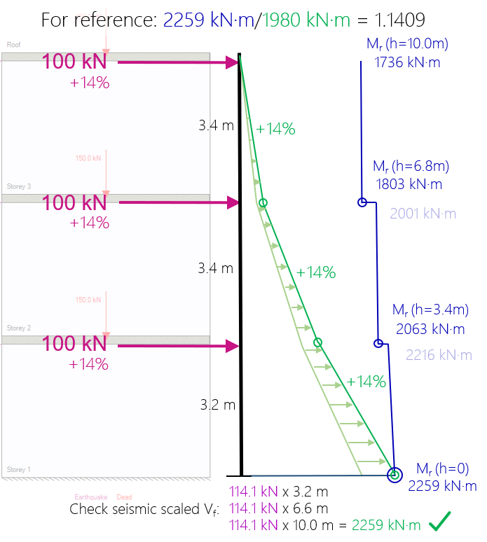
By considering and comparing flexural behavior at only the base, the shear amplification pattern is reduced as shown below:
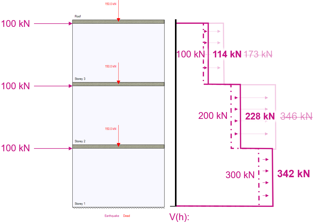
While the in-plane factored shear that must be designed for at the base remains unchanged, the factored shear at storey 2 is now 228 kN, reduced from 346 kN, and the factored shear force at storey 3 is now only 114 kN, reduced from 173 kN using the original procedure.
Note: While no longer critical for any of the storeys in this example, 16.5.4 (b) should always be considered and checked against for designs.
Concluding Thoughts
The basis for this change is based on the argument that part (a) of the various shear force amplification clauses can be considered satisfied for the entire multi-storey shear wall by performing this check just once at the base.
These limits can be hard enough to satisfy without making it even harder with added degrees of conservatism.
If there are any questions regarding this change, design example, or whether this has an impact on a particular design you are working on, please do not hesitate to contact MASS technical support.