

Latest Software Blog Posts
Why is the Factored Shear Force Scaled Up for Seismic Considerations on a Shear Wall Design?

Explaining these clauses and how they are applied
Questions about the seismic effects on shear resistance? Click here for a separate post. This page covers the scaling up of seismic forces applied to the wall.
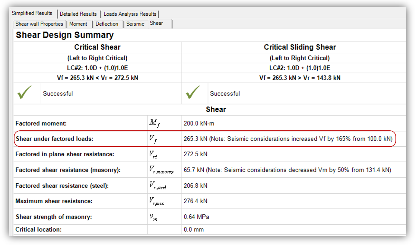
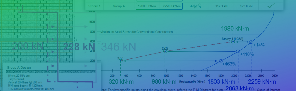
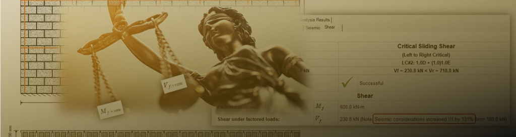
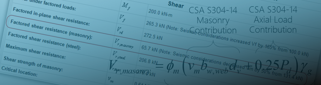
You may have noticed after running a few designs in the newly released MASS Version 4.0 that when it comes to shear design and seismic loading combinations, factored shear can be amplified by a significant amount. Results such as what are shown below can be common for shear walls and specifically, load combinations with earthquake loads:
While a number of new features have made their way into MASS Version 4.0 (multi-storey shear walls and boundary elements come to mind), it is the added seismic provisions that were previously left outside the scope of MASS which are coming into play here.
Disclaimer: This post is exclusively intended to provide insight into the approach taken by the MASS design software in interpreting a CSA S304-14 code compliant seismic design. It is up to the professional discretion of the designer to input an appropriate layout, boundary and loading conditions, interpret the results, and determine how they should be incorporated into their designs. As per the end user license agreement (and also recommended within PEO’s guidelines for using engineering software), a tool cannot be considered competent and reliance on a tool does not relieve the user of responsibility.
This requirement is shared by four different clauses. While there are key differences between each clause which are specific to different designs and SFRS classifications, requirements are summarized below:
Minimum Required Factored Shear Resistance
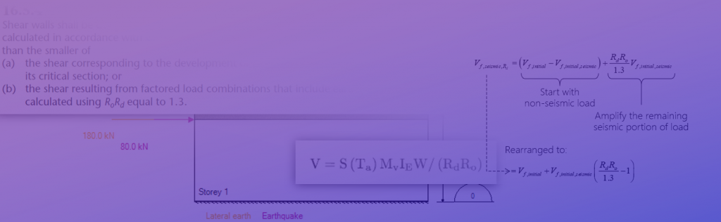
Shear walls shall be designed to have a factored shear resistance and factored sliding shear resistance greater than the shear due to the factored loads, but not less than the smaller of:
a) the shear corresponding to the development of the moment resistance of the shear wall at its critical section; or
b) the shear resulting from the factored load combinations that include earthquake effects, with loads calculated using RdRo equal to 1.3.”
Note that this is a summary for illustrative purposes, and is not the text of an actual clause. The actual clauses in the CSA S304-14 and their differences are covered further down this post. If there are any discrepancies between what is shown in this article and the clauses in CSA S304 or the National Building Code of Canada (NBCC), the codes and standards shall be applied apply.
The subsequent sections will cover the approaches outlined in part A and part B.
Part A: Ensure Ductility by Failing in Flexure
Part A is meant to ensure that the wall will fail in flexure under seismic loading… no matter what! Shown below for reference:
” a) the shear corresponding to the development of the moment resistance of the shear wall at its critical section…”
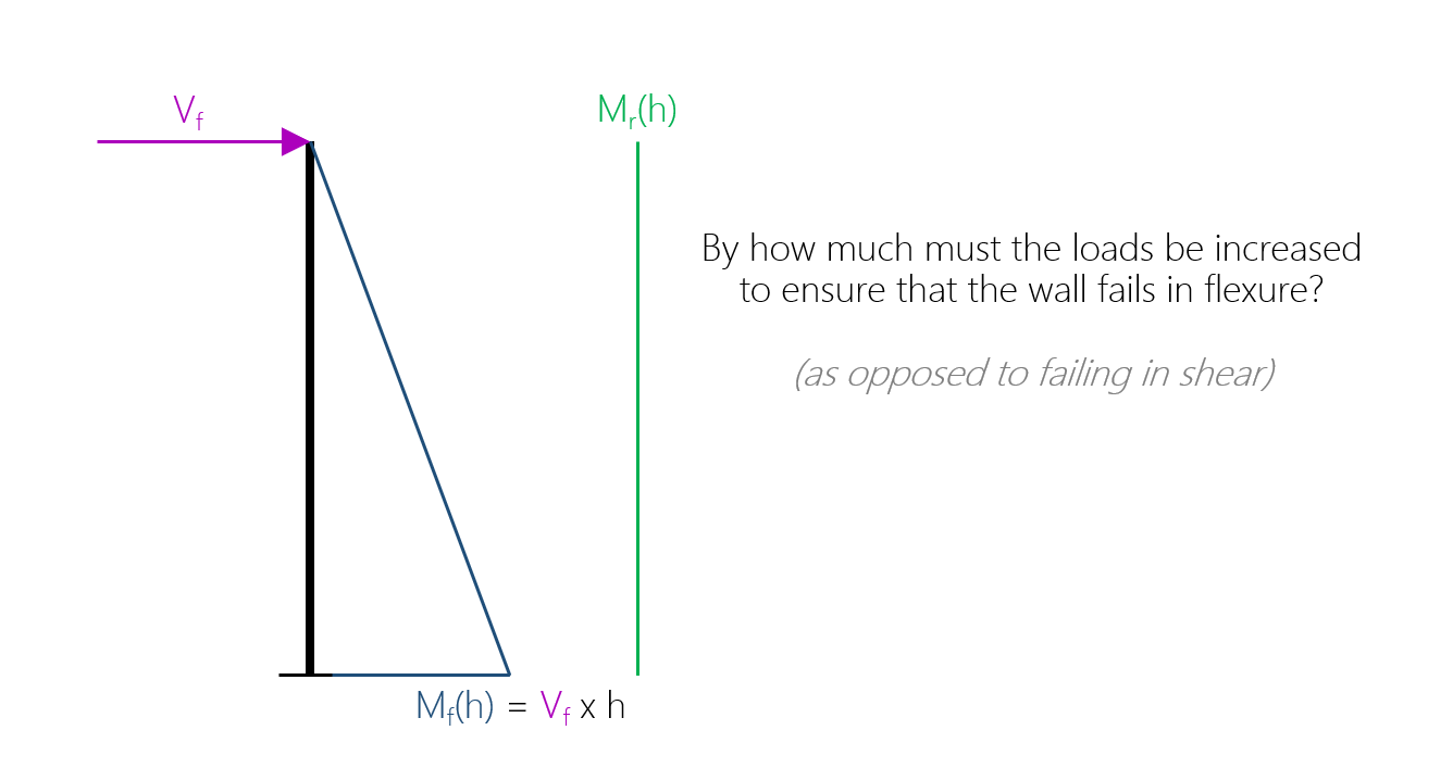
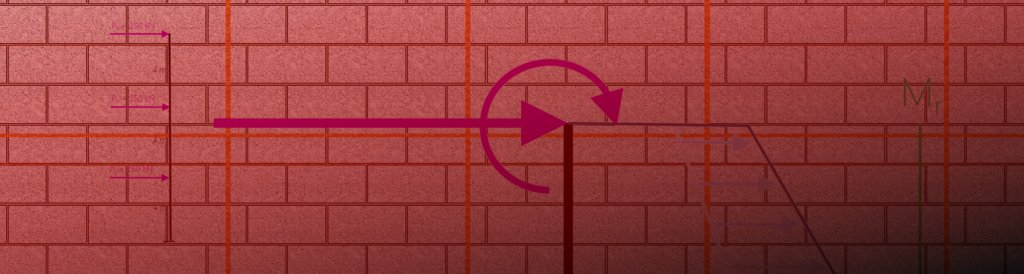
If you think backwards from the scenario where a shear wall fails in flexure, the moment experienced at the base of the wall exceeds the moment resistance at that location. For typical shear walls which act as a cantilever (fixed from rotating at the base and free to move at the top), a lateral load is resisted by the wall, causing a shear force equal to that lateral load and an overturning moment that is greatest at the base, equal to the lateral load multiplied by the height.
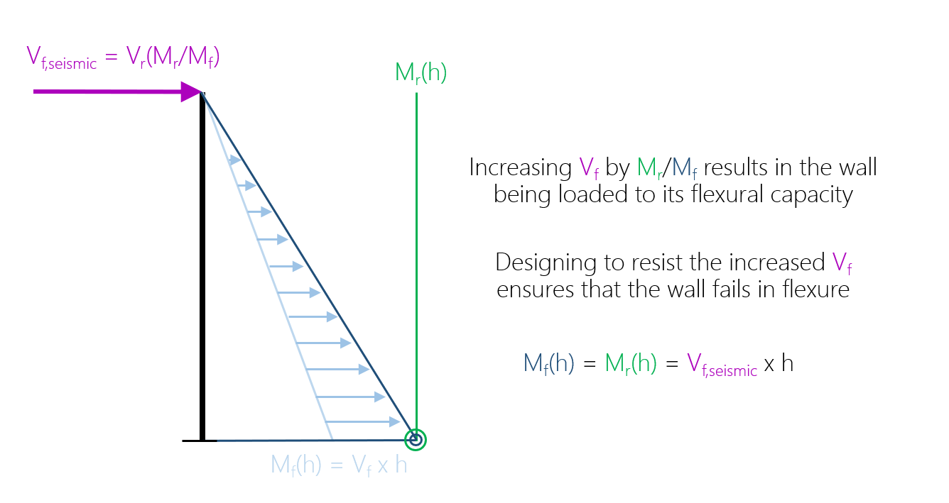
In order to determine the increased shear force to design for, an increased factored moment is set equal to the moment resistance at that same location
Side note: This might seem like an oversimplification compared to multi-storey configurations where several lateral loads are applied along the height of the structure. The principles work exactly the same way. This process is handled at the element level within MASS so it is always looking at a single storey with loads already distributed and applied at the top of that particular element.
Going back to looking at the exact point in which some applied load causes the wall to fail in moment, this fictitious lateral load is equal to the shear force described in part a. By applying this part of the clause, we are effectively ensuring that the design that will not experience a sudden shear failure mechanism in the event of an overload. This is because the wall has been designed to resist an artificially scaled up lateral load causing the wall to fail in flexure, associated with in-plane bending and deflection.
For a more detailed explanation covering part (a), click here to see the full post explaining the concept with an example.
Part B: Not Overestimating Overstrength and Ductility
When calculating seismic loading on a structure, the NBCC outlines a method in which the equivalent static forces are inversely proportional to seismic force modification factors: Rd for ductility, and Ro for overstrength. This section of the clauses the product of these two factors is replaced by 1.3. Part b is shown below for reference:
” b) the shear resulting from the factored load combinations that include earthquake effects, with loads calculated using RdRo equal to 1.3.”
Based upon the three SFRS options available for reinforced masonry design, the net effect on factored shear is shown below:
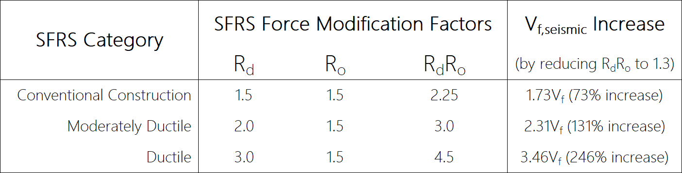
Note that since this is one of two possible increases where the lesser value is used, the percentages seen here will not necessarily be applied and can be interpreted as upper limits, based on what is calculated based on the part (a) requirements.
One of the benefits of designing a structure with higher levels of ductility is being able to reduce the magnitude of earthquake loads, factoring in the structures ability to deflect and absorb energy. The same is true of overstrength, however, only the value of 1.5 is available for reinforced masonry applications. Part B effectively negates a portion of these benefits for purposes of designing around diagonal and sliding shear.
Putting A and B Together
Each of the clause requirements are independently considered in MASS. The software then compares the results and assigns a new variable value, Vf,seismic, to represent this amplified shear force that is to be designed around.
Since the smaller value of the two is what will be used for design, the standards are ensuring that we are not both counting on the shear wall failing in flexure, as well as including ductility that may not exist for a shear failure. One or the other is permitted but not both at the same time.
As stated in the clauses listed in the section below, shear walls in MASS are designed to not only have a shear resistance, Vr, that exceeds factored diagonal shear, and factored sliding shear, but also exceeds the value modified to take the effects outlined on parts (a) and (b) into account, described above.
Getting into the specific clauses…
… and understanding when each one is used and what the differences are.
The clauses are shown for reference below, taken from the various sections of CSA S304-14: Clause 16 covering earthquake design considerations. The illustrative summary seen earlier is meant to capture the spirit of these clauses and the common elements between them. Designers should always reference their own copies of any design standards.
The first SFRS category covered is the most commonly used Conventional Construction where the SFRS force modification factor for ductility is equal to 1.5.
16.5.4 – Conventional Construction
This can be thought of as the default version of the clause, matching the summary and process described earlier in this article. An excerpt is shown below:
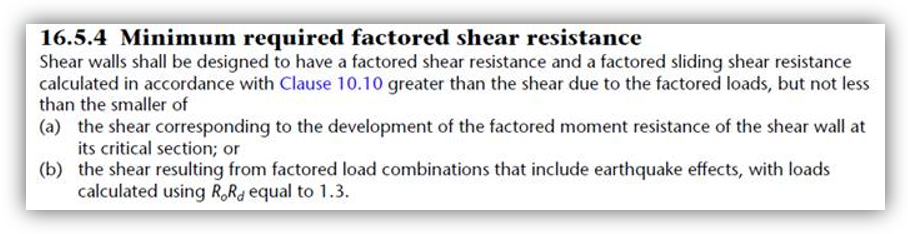
When describing differences in the other clauses below, CSA S304-14: 16.5.4 will be the reference point to which all other comparisons will be made.
In cases where the importance category of a structure is “Post Disaster” or the height exceeds what is allowable for conventional construction, increasing the SFRS ductility may be required. Among other added design considerations, the process of calculating Vf,seismic will differ slightly. Starting with Moderately Ductile shear walls, these are divided into squat and on-squat sections, with squat covered in the section below.
16.7.3.2 – Moderately Ductile Squat Shear Walls
Shear walls with a height to length aspect ratio below 1.0 and a ductility SRFS modification factor of 2.0 are classified as Moderately Ductile Squat shear walls. In these cases, the following clause is applied during shear design:
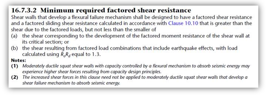
This clause is very similar to what has been discussed in the summary, as well as for Convention Construction designs. Where the requirements deviate is in the two notes which add both clarity and some ambiguity into the design process.
Note (1): A Warning on Part (a)
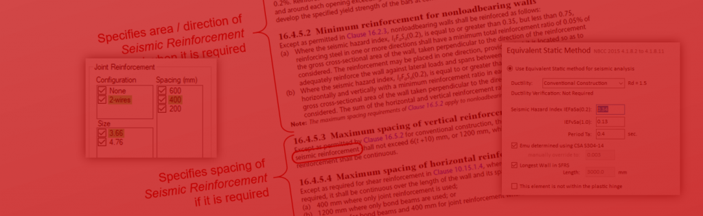
Note 1 is more or less cautioning the user that their designs may be significantly affected for shear walls within this SFRS category, shown below: for search indexing purposes
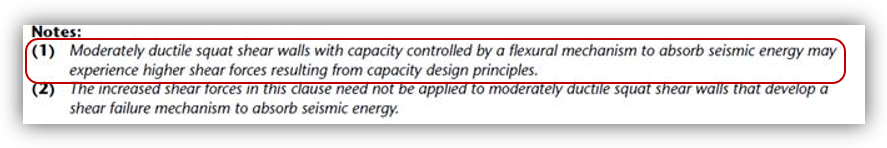 Moderately ductile squat shear walls with capacity controlled by flexural mechanism to absorb seismic energy may experience higher shear forces resulting from capacity design principles
If you picture a squat shear wall, chances are that it has a long cross section placing it in this category. Since shear wall moment resistance is largely affected by section length (and associated moment arms between coupling tension and compression internal forces), squat shear walls tend to have a very high moment resistance.
For designs with large moment resistances, the scale factor used to amplify the in-plane factored shear forces tends to also be relatively high. What ends up happening is the design requiring an increased area of horizontal reinforcement compared to what might have been expected or what would be needed for a design resisting the same magnitude of force from a non-seismic load case.
This note effectively serves as a warning to not be surprised by more joint reinforcement or larger bond beams at tighter spacings, as these can be typical for shear walls within this SFRS category.
Note (2): Considering the Failure Mechanism
Note 2 is so interesting that it has its own dedicated post here and reads as follows:
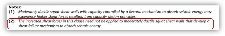 The increased shear forces in this clause need not be applied to moderately ductile squat shear walls that develop a shear failure mechanism to absorb seismic energy
This note serves to provide an escape from having to invoke the earlier parts of this clause. As a result, the software checks the design and evaluates whether a flexural or shear mechanism is more likely to develop.
Differentiating Flexural Failure from Shear Failure
MASS compares the relative percentage of factored loading to resistance for both moment and shear. If the wall is loaded closer to its bending capacity than its shear capacity, MASS identifies that a flexural mechanism occurs and parts a and b are each applied normally. If the wall is loaded relatively closer to its shear capacity than its moment capacity, MASS identifies this situation as a shear failure mechanism and as a result, uses Note 2 to apply no amplification of scaling to the factored diagonal or sliding shear.
As mentioned earlier, a more detailed post covering this scenario is linked here. This amplification is explained earlier in this post within part (a) and also has a more detailed companion post, linked here.
These two notes are specific to Moderately Ductile shear walls that are also identified as being squat. For all of the non-squat designs using the same ductility SFRS force modification factor of 2.0, the seismic approach to shear design is covered in the section below.
16.8.9.2 – Moderately Ductile (Non Squat) Shear Walls
For shear walls with a height to length aspect ratio greater than or equal to 1.0 with a ductility SFRS modification factor of 2.0, the following clause is applied during shear design:
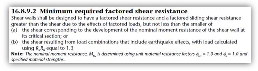
As an added layer of conservatism, moderately ductile shear walls (often very tall or Post-Disaster) are done with a wrinkle to the moment resistance listed in part (a). As opposed to the “factored moment resistance”, or Mr, that is used to scale up the lateral load and shear force, a new term is introduced: the nominal moment resistance, or Mr,nom. This is where the fun begins.
The process needed to calculate the nominal moment resistance is seen in the note beneath part (b). Rather than using the standard material resistance factors for masonry and deformed reinforcing bars as part of standard limit states design, they are effectively removed from consideration by setting them equal to 1.0. I will not comment as to why other than just saying that since this calculation is concerning the overall behaviour of the wall and trying to predict the particular mechanism in which it would fail, a more likely moment resistance is used instead of targeting a minimum threshold in order to satisfy a confidence interval.
Since the larger resistance factors will result in higher material strength values, the shift from using factored to nominal moment resistance further increases the seismic amplification of the factored shear that must be designed around.
16.9.8.3: Ductile Shear Walls
For shear walls with a ductility SFRS modification factor of 3.0, the following clause is applied during shear design:
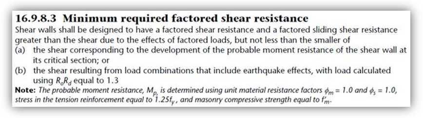
The changes seen here are similar to those found in moderately ductile non-squat shear walls with another term introduced: probable moment resistance, or Mr,prob. The same material resistance factors used in nominal moment resistance are listed in the note below the clause with an added modification related to the reinforcement.
The yield stress of bars in tension is changed to 1.25fy, or 500MPa in most cases where 400MPa was the strength used for capacity design. This is to take strain hardening into account where by default, the stress is kept constant once the bar reaches yield strain. Since ductile walls are meant to absorb more energy compared to conventional construction or moderately ductile walls, larger strains are expected in bars along the tension side of the wall so this provision is intended to help better determine the more likely shear force that most be designed around to ensure a flexural failure mechanism.
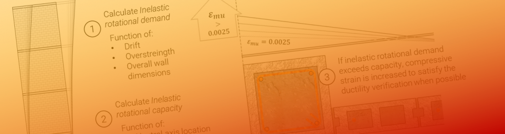
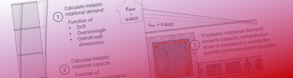
Increased Compressive Strains
Getting into boundary element design, where it is possible to achieve higher strains in compression through the use of a boundary element explained in CSA S304-14: 16.11, it is possible for a moderately ductile design so have its shear considerations changed to match what is done for a ductile design. Clause 16.10.4.3 outlines this requirement, shown below:
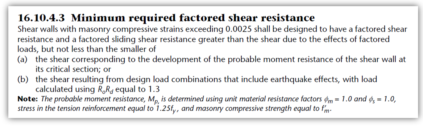
Shear walls designed as a ductile SFRS will not experience any different factored shear amplification as this requirement matches what is already required for those cases.
While this article strictly covers the seismic amplification of shear forces under seismic load combinations, there are additional considerations in calculating in-plane shear resistance based on a larger maximum compression strain covered in a different post here.
Concluding Thoughts
If you’re still reading, I hope this was useful in answering any questions and adding some insight into how shear design is affected by seismic considerations.
If there are still any questions, CMDC – the authorized technical service provider for MASS – is available to offer support.
Additional Reading: Why ISN’T the Factored Shear Force Scaled up for a Seismic Design?

Never before have my eyes melted back into my skull from seeing content so informative. I’m now blind but it was worth it.