

Latest Software Blog Posts
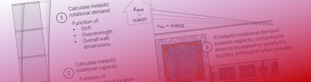
Why doesn’t MASS consider Type 6 Structural Irregularities?
With MASS Version 4.0 moving into Multi-Storey Shear Wall design, why doesn’t the software check for something that seems squarely within its expanded scope?
Dating back a few years in the MASS development process, a lot of work was put into adding the capability for the software to check for structural irregularities that are outlined in the National Building Code of Canada. With the addition of a multi-storey shear wall module, the ability for the software to see what was designed at different heights along the structure made it seem feasible for MASS to also start detecting irregularities and even design around them if needed.
Disclaimer: This post is exclusively intended to provide insight into the approach taken by the MASS design software in interpreting a NBCC and CSA S304-14 code compliant seismic design. It is up to the professional discretion of the designer to input an appropriate layout, boundary and loading conditions, interpret the results, and determine how they should be incorporated into their designs. As per the end user license agreement (and also recommended within PEO’s guidelines for using engineering software), a tool cannot be considered competent and reliance on a tool does not relieve the user of responsibility.
As outlined in the Multi-Storey Design Strategy page (click here to open in new tab), the software deigns around irregularities that can be reasonably considered within the scope of detection when viewing just a single wall within a larger structure. For example, a Type 5 irregularity (out-of-plane offsets) can be concluded to be beyond the scope of the multi-storey module as those types are designs are not possible within the software’s user interface.
Irregularity Background Information
Type 1 and 4 structural irregularities related to stiffness (both cracked and uncracked) can be detected within a wall design and are available options within the MASS software. Whether or not the user wishes to perform these checks is optional since what triggers an irregularity for one element of a Seismic Force Resisting System (SFRS) may not automatically result in an irregularity for the SFRS as a whole. Additionally, the user also has the option to design around irregularities as they may know from the outset of their design that they are designing a “regular” structure within the NBCC seismic classifications. This might be the same for a design that has the importance category of “Post-Disaster”.
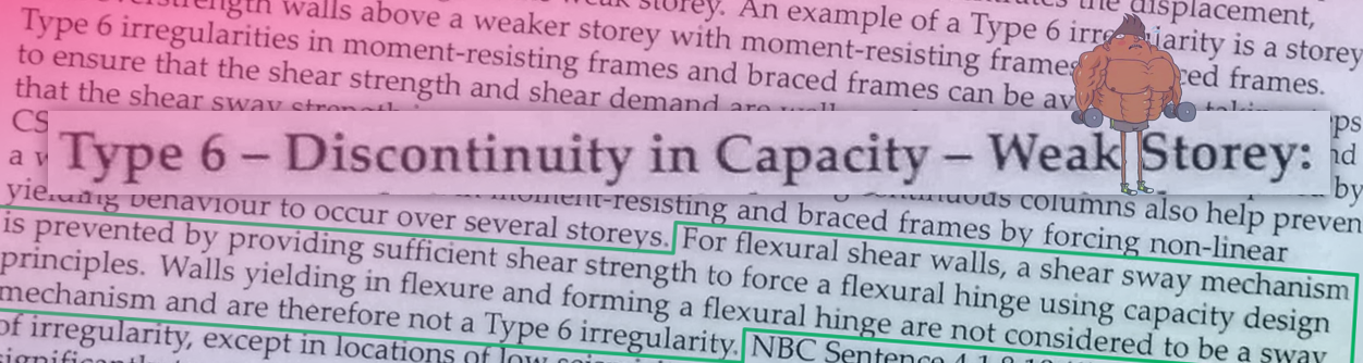
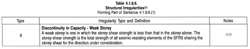
When it comes to Type 6 irregularities, this gets a little bit more complicated because at first glance, it seems obvious that based on the NBCC Type 6 definition (shown below), this is something that easily fits within the scope of MASS and should be incorporated into the multi-storey shear wall module.
For over a year, alpha builds of MASS Version 4.0 included a Type 6 irregularity check and the option to design around these to keep the wall designs regular between storeys. The check was simple enough to incorporate where what we did was simply take the lesser of the diagonal and sliding shear resistances and compared it to the governing shear resistances of the storeys below.
Appearing in “Regular” Designs?
Early in the testing process, designs with earthquake loads applied would frequently be observed to be designing around irregularities. This would be true even for designs using one group of properties, uniform their design and construction from top to bottom. Below is a screenshot from an older alpha build where the cross section design is uniform for all four storeys. Despite the same cross section being used along the full height, Type 6 irregularities were constantly popping up which prompted further investigation. The bottom four cells list the governing shear resistances with Storey 1 at the bottom and reporting upward.
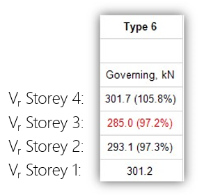
Note the shear resistance of storey 4 being larger than the three beneath where storey 3 is shown in red, being the first “weak storey” identified.
You might ask “How can an irregularity be detected when almost by definition, the cross section was regular along the entire height (same block strength, size, and reinforcement pattern throughout)” and you would be correct. The author was wondering the same thing about a year ago.
My first thought was that intuitively speaking, higher axial load should only improve the concrete and grout aggregate interlock, stiffening and strengthening the structure from the top, working your way down. I assumed there was a bug in the shear resistance calculations but as it turned out, the software was performing exactly as we had intended.
Are the CSA Standards to blame?
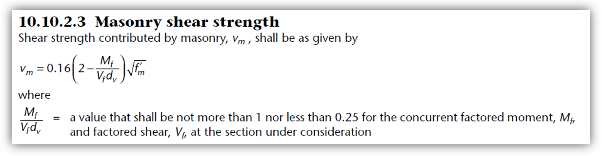
Digging deeper into the software code and masonry calculations, no bugs could be found but instead, an issue with the way that the CSA standards calculate masonry shear strength, in MPa, shown below:
The issues with irregularities that pop up for seemingly regular structures is a result of the (2 – Mf/Vfdv) factor and how it changes along the height of a shear wall. For a fairly ordinary multi-storey shear wall design with regular lateral and axial loads coming in at each floor location, the relationship along the height of the structure for a regular 4 storey structure with equal lateral point loads applied at each floor shown below:
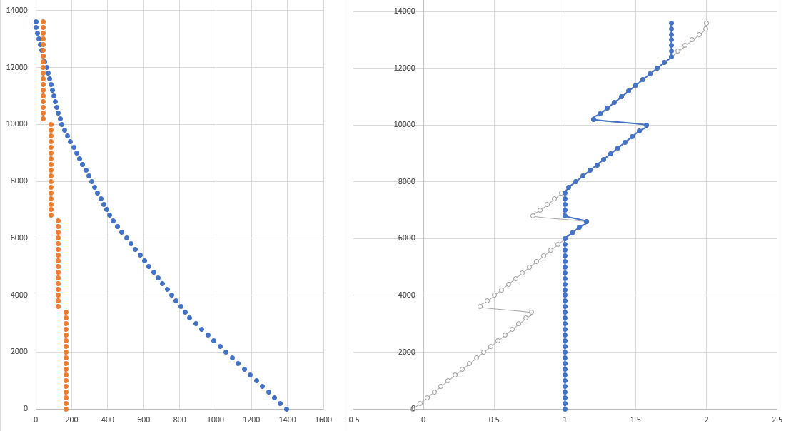
The left plot shows the resulting factored shear along the height in orange and the factored moment profile in blue. In the chart to the right, the grey plot shows the (2 – Mf/Vfdv) term without limits and the dark blue shown the same term with the code mandated lower limit of 0.25 and upper limit of 1 applied.
Masonry shear strength is directly proportional to the (2 – Mf/Vfdv) term with the limits applied and as s result, this shear wall has storeys with lower shear strengths below storeys with higher strengths. These errors were being correctly triggered by the letter of the law of how the irregularity detection had been intended and implemented. After spending some time into parsing the exact language of the NBCC, it seemed inevitable that we would need to deal with these supposed irregularities.
Turning to the Commentaries
In hopes of finding some more guidance, the NBCC structural commentaries were referenced.
The Type 6 excerpt of the NBCC structural commentaries is shown below:
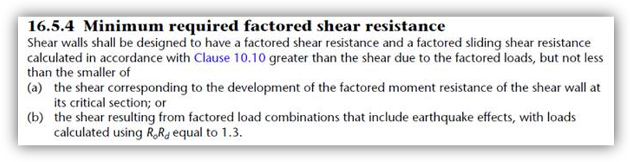
Plain text shown below: “For flexural shear walls, a shear sway mechanism is prevented by providing sufficient shear strength to force a flexural hinge using capacity design principles. Walls yielding in flexure and forming a flexural hinge are not considered to be a sway mechanism and are therefore not a Type 6 irregularity.”
The applicability of a Type 6 irregularity depends on the identification of a “flexural hinge mechanism”. Going back to the specific NBCC commentaries’ language, this comes down to whether or not it can be argued that the design can be counted as “providing sufficient shear strength to force a flexural hinge using capacity design principles”. While this is not explicitly stated within the CSA Standards for masonry shear wall designs, there are clauses in chapter 16 of CSA S304-14 that can be argued to accomplish this indirectly through an additional increase of factored shear so that the wall is designed to fail in flexure.
From the perspective of the software, increasing the factored shear force at the critical cross section within a design is how this is done. In order to get a successful design result, MASS must satisfy this larger shear force requirement by iterating cross sectional properties until the shear resistance has increased enough to eclipse the amplified seismic shear force.
Note: This is only done for seismic load combinations, defined within the software as load combinations with an “Earthquake” type load included.
Side note: something similar exists for the other irregularity type checked in MASS: the Type 1 bending and shear stiffness irregularity. This is the requirement that basically says you can not have large drops in stiffness working your way up the height of a shear wall and still be considered “regular”. If an irregularity is identified based on using cracked stiffnesses, the uncracked stiffness values can be compared and be used to designate a wall as regular if the unreinforced stiffensses are close enough together. MASS performs this check as well.
How this is handled within CSA S304-14
For more details and further explanation, visit the main seismic shear design linked here. The relevance clauses are simply listed below for reference.
Conventional Construction Shear Walls
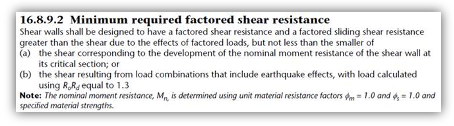
For all “conventional construction” shear wall designs, factored shear is modified based on the CSA S304-14: 16.5.4, shown below:
More detailed information on the software’s implementation of this clause can be found here.
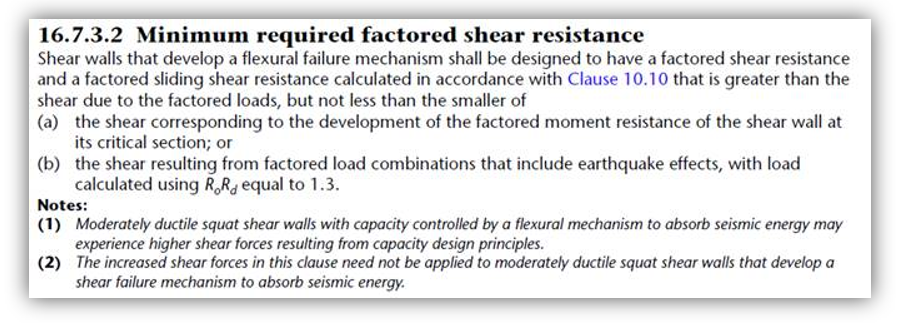
Moderately Ductile Shear Walls
Designs with a ductility SFRS force modification factor of 2.0 or higher that are taller than they are in length are required to have a detailed plastic hinge region. While this on it’s own may be considered enough to match the language in the NBCC commentaries highlighted above, shear design is also affected using the clause shown below:
Again, more detailed information on the software’s implementation of this clause can be found here.
The Exception for Squat
Shear walls designs using CSA S304-14: 16.7 contains an additional note which can possibly prevent parts (a) and (b) from being applied to a design:
Note 2 is outlined in more detail in a dedicated post here. When this condition is met and factored shear is not scaled up to account for seismic effects, a Type 6 Irregularity would technically apply and need to be checked for manually. Since the entirely of CSA S304-14: 16.7 applies to squat shear walls, the likelihood of a SFRS of this type being used for a multi-storey shear wall with changing cross sections was considered so remote that Type 6 checks were removed form MASS altogether.
If anyone reading this is looking at designing a multi-storey structure with changing cross sectional properties between floor locations, using a squat masonry SFRS that is moderately ductile, please feel free to reach out and let me know.
Note: If some walls of this SFRS are non-squat, a plastic hinge region is required so the layout should be adjusted in such a way that the full SFRS falls within CSA S304-14: 16.8.
Ductile Shear Walls
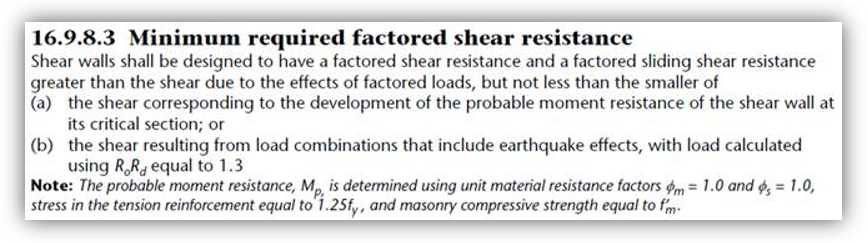
And for Ductile shear walls (Rd = 3.0), CSA S304-14: 16.9.8.3 shows how shear design considers this behaviour:
Once again, more detailed information on the software’s implementation of this clause can be found here. This may be a broken record but any further questions are likely addressed in the more detailed series of articles (including examples).
It is not uncommon to see the factored shear increased by 250% as a result of these clauses.
Concluding Thoughts
Hopefully this post is helpful in offering some insight behind the decision to omit Type 6 Irregularity checks form MASS Version 4.0. With the exception of the theoretical possibility of a multi-storey but also squat SFRS, Type 6 Irregularities are not detected by MASS because of how shear design through various clauses is intended to ensure flexural failure.

Have any questions, comment, or concerns? Please feel free to post below or contact be directly with feedback on how you would deal with weak storeys in a masonry shear wall.