

Latest Software Blog Posts
Failed the Ductility Verification? How to Pick a Higher εmu, the Maximum Compressive Strain
The addition of boundary elements to MASS Version 4 (as well as CSA S304-14) means that failing a ductility verification is not the end of the line
Boundary elements allow for the confinement of reinforcement in compression. Not only does this unlock more flexural capacity as steel in compression was previously ignored, but it also allows the option to design for additional ductility to be factored into the design.
Upon failing a ductility verification, the MASS software will automatically try and determine a passing maximum compressive strain that will allow the design to be successful. The process used to determine that increased compressive strain for a given cross section is the topic outlined in this post.
Disclaimer: This post is exclusively intended to provide insight into the approach taken by the MASS design software in interpreting a CSA S304-14 code compliant seismic design. It is up to the professional discretion of the designer to input an appropriate layout, boundary and loading conditions, interpret the results, and determine how they should be incorporated into their designs. As per the end user license agreement (and also recommended within PEO’s guidelines for using engineering software), a tool cannot be considered competent and reliance on a tool does not relieve the user of responsibility.
Note that the topic of a designer’s strategy in addressing a failed ductility verification may be the topic for a future post or paper. That is an article for another day with a much larger scope. Even MASS doesn’t continue the cross section iteration process for Multi-Storey Shear Walls since it is a function of so many
Why increase εmu at all?
When designing shear walls with higher levels of ductility than what would be exhibited in conventional construction, a ductility verification is required that must be satisfied.
For moderately ductile shear walls, this verification is outlined in CSA S304-14: 16.8.7
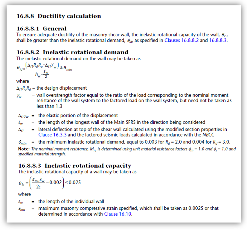
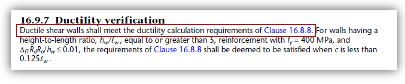
Ductile shear walls also are required to have satisfied the ductility verification, specified in CSA S304-14: 16.9.7 which refers back to clause 16.8.8.
(CSA S304-14: 16.8.7 offers similar exception criteria for moderately ductile shear walls that is checked internally by MASS but was not included in this post)
Note: These walls must also be non-squat, having a height-to-length aspect ratio greater than or equal to 1.0 for a ductility verification to be required. Moderately ductile squat shear walls have their own set of provisions in CSA S304-14: 16.7 and ductile squat shear walls are prohibited in accordance with CSA S304-14: 16.9.2.
Why not just max it and call it a day?
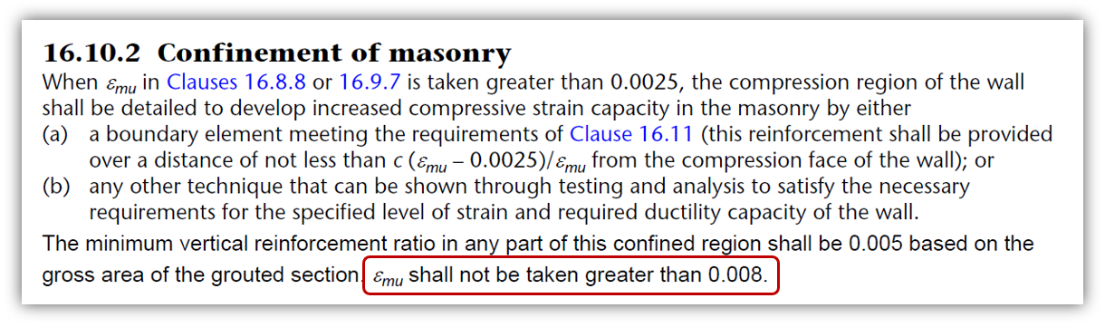
If the maximum strain must be increased in order to satisfy the ductility verification, you may ask why not simply jump up to the maximum listed at the end of CSA S304-14: 16.10.2?
Increasing εmu by 320% is a massive jump and while it would be the most certain way of addressing any ductility verification issues, it introduces new considerations into the shear wall design. In the section outlining other factors to consider, this post will explain the other considerations in determining how high the maximum strain can be increased.
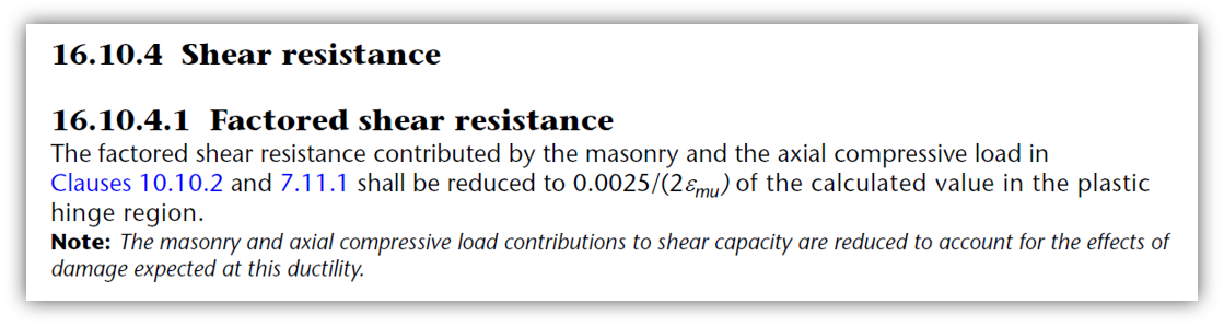
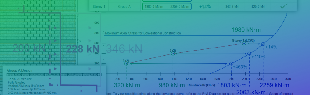
To give one example, the shear resistance component coming from the masonry and axial load is reduced beyond the 50% reduction for ductile shear walls depending on the degree to which εmu has been increased.
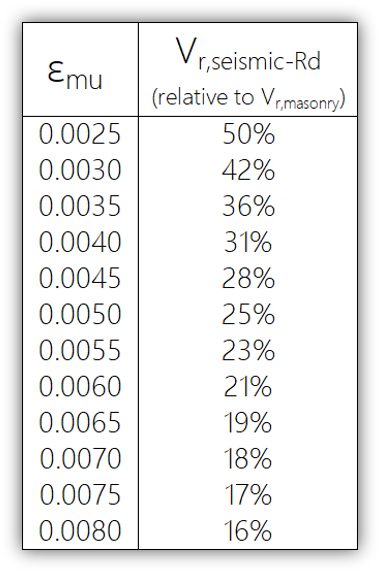
As seen in the table above, jumping all the way up to εmu results on only being able to count on only 16% of the in-plane shear resistance coming from the masonry and axial load, in accordance with CSA S304-14: 16.10.4.1:
As referenced earlier, there are other factors that can get in the way of increasing the maximum compressive strain by too large of an increment. This post will review some terminology and then outline the steps in which the MASS software goes about the process of selecting a εmu to address a failing ductility verification.
Terminology and Background
Several terms will be mentioned here and in the subsequent sections. Many are defined within CSA S304-14 whereas some others have been derived and applied within the MASS software for the purpose of satisfying the ductility verification.
Defined within CSA S304-14
The terms below are defined within the CSA Standards:
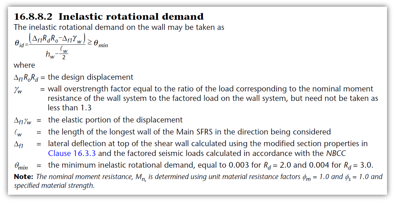
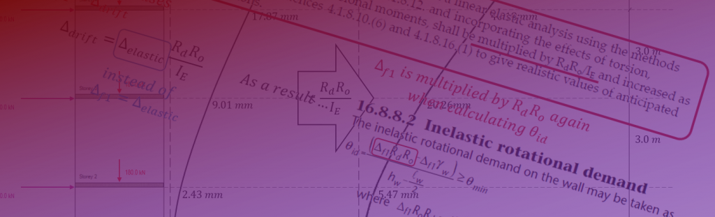
θid: Inelastic rotational demand, measured in radians (dimensionless)
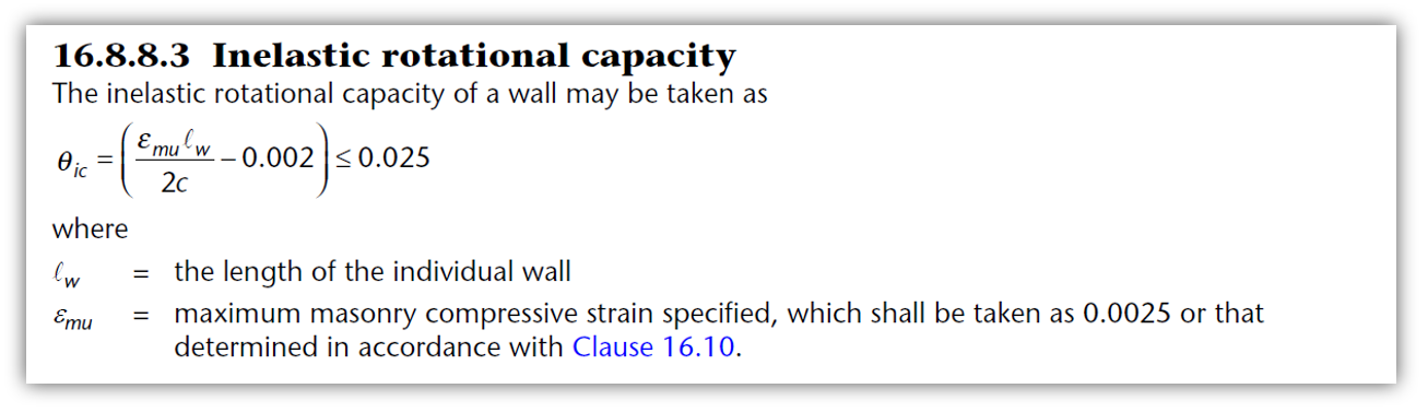
θic: Inelastic rotational capacity, measured in radians (dimensionless)
εmu: Maximum ultimate compressive strain
c: distance from the compression edge of the shear wall to the neutral axis, measured in mm.
Defined within MASS
The terms below have been defined for purposes of attempting to satisfy the ductility verification.
εreq,duct.: Required minimum εmu in order for θic to meet θid:
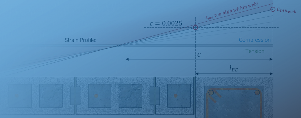
εreq,web: Maximum allowable εmu to keep strain in the web from exceeding 0.0025.
εreq,ties: Maximum allowable εmu based on ties confining compression of longitudinal reinforcing bars.
εreq,max: Absolute maximum upper bound taken from CSA S304-14: 16.10.2.
εreq,gov: The governing limit between εreq,web, εreq,ties, and εreq,max. used to evaluate εreq,duct. in Step 3.
If the ductility verification is satisfied using the default εmu of 0.0025, there is no need to do anymore work. If the cross section does not contain boundary elements then the cross section properties such as the masonry unit and reinforcement pattern must be changed.
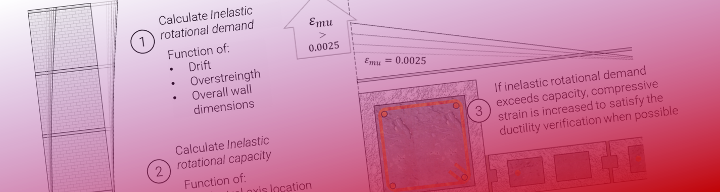
Step 1: Fail Ductility and Calculate εreq,duct.
Once the first attempt at satisfying the ductility verification has failed using εmu of 0.0025, MASS will then calculate the numerical value that would have increased θic to equal θid. Using the calculated result (taking the code minimum into account), the following expression can be derived and used to calculate εreq,duct.
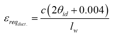
Since one of the inputs to this expression is c, there can be several load combinations that the new strain increase must be able to accommodate. As a result, the largest calculated εreq,duct. is selected for consideration.
Another way to think of this step is as if the software observed a failed ductility verification, and then stops and asks the question “I know that I failed, but what strain would have theoretically gotten the job done?”
Once this value has been selected for consideration, it is time to potentially rain on the parade.
Step 2: Compare εreq,duct. to consider other factors
There are other factors to consider when selecting a new εmu before diving back into the ductility verification.
Factor 1: εreq,web and protecting the web at all costs
Just because the boundary elements allow for higher strains does not mean that the web is able to be taken along for the ride without being completely destroyed. This is baked in the standards in the form of CSA S304-14: 16.11.2 which is explained in its own dedicated post here.
This is also checked within MASS in the form of a geometry check, although since it is a function of c, axial loading will be the driving force behind what this minimum boundary element length can be set at.
Any designs with attempted strains above the calculated value for εreq,web will trigger the error message related to minimum boundary element length. As a result, any potential values of εmu exceeding εreq,web can be ruled out as candidates in order to satisfy the ductility verification.
Factor 2: εreq,ties and based on tie confinement
This is a complicated limit to explain so for the purposes of keeping this short and digestible, take the author’s word that there are sometimes cases where the ties can only accommodate a limited increase in εmu which can possibly govern the value selected to satisfy the ductility verification.
Any designs with attempted strains above the calculated value for εreq,ties will trigger the error message related to minimum boundary element ties. As a result, any potential values of εmu exceeding εreq,ties can be ruled out as candidates in order to satisfy the ductility verification.
Practically speaking, this limit is unlikely to govern as MASS also tried to address this limit by placing ties closer together when required.
Factor 3: εreq,max & the limit of how far science can go
Any designs with attempted strains above the calculated value for εreq,max will trigger the following error message:
Design fails: Maximum compressive strain cannot exceed 0.008 in accordance with CSA S304-14:16.10.2
As a result, any potential values of εmu exceeding εreq,web can be ruled out as candidates in order to satisfy the ductility verification.
These three factors are relevant for consideration before re-attempting the ductility verification with an updated compressive strain.
Step 3: Determine now if all hope is lost for this design.
If the strain cannot be increased to εreq,duct. without exceeding the other factors considered, it can be safely concluded that it is not possible for this design to be successful. When this is the case, the following message is displayed by the software.
Design fails: Ductility verification unsuccessful and maximum compressive strain can not be increased and also satisfy CSA S304-14: 16.10.2, 16.11.2, or 16.11.6.
Note that MASS will not continue redesigning the shear wall at this stage. Failed ductility verifications can be a function of so many variables that a single algorithm is not currently in place that will address all of them. Something may be developed in the future based on designer feedback and information from projects where this arises as an issue.
If the value of εreq,duct. can be achieved without exceeding any of the other factors, the software can safely conclude that it is possible to satisfy the ductility verification and proceed to the next step.
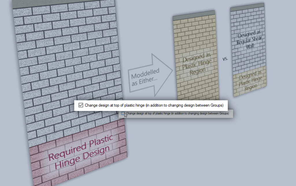
Step 4: Determine and set targets (strain and strain to c ratio)
At this stage, the required compressive strain and strain to neutral axis ratios are calculated and saved. These targets are needed to prevent circular loops where a strain is calculated, the shear wall is re-designed using that new strain, and then found to still not satisfy the ductility verification – again!
Step 4a: Starting with the governing strain
Since it has been determined that is it possible to satisfy the ductility verification by increasing strain, the governing value is saved as a target. This also serves as a starting point when re-analyzing the section and balancing forces using a new strain profile.
While it might seem simple and straightforward to use this value and call it a day, changing the strain used at the compression edge of the shear wall impacts so much else that a second target needs to be sat and saved as well.
Step 4b: Adding a Target for the Strain to Neutral Axis Ratio
When the strain profile is changed, not only is the strain experienced in each reinforcing bar affected, but the required compression zone will be impacted as well. The internal compression zone (80 percent of the distance to the neutral axis for most unit strengths) is calculated to balance the total tension and compression forces to the applied axial load. Since the neutral axis is another key input of θic, simply relying upon a target strain will not be sufficient in addressing a failed ductility verification. Not only that, but the added tension in bars near the neutral axis will require more masonry compression to offset that change, all but guaranteeing another failure.
This relationship is so complicated and differs specifically based on the details of each situation that rather than attempt an analytical approach to solving it, the MASS software simply saves a required strain to c ratio that must be satisfied and also checked. The strain is incremented until both targets are met.
Step 4c: Actually hitting the targets
Once the targets are determined and saved, MASS goes back to the very beginning of the moment design and adjusts εmu to the target. The forces are balanced for each load case and the new value of c is used to check the second target. If it is met then the software continues on but in most cases, the ratio target is not satisfied and MASS slightly increments εmu and keeps checking until either the maximum governing value is hit or both targets have been hit.
Step 5: Re-perform design to instant success!
By this step, all of the work has been done to ensure that the ductility will be successful on the second attempt. While running the check a second time may seem redundant since the strain used was based on what will satisfy the ductility verification from the first attempt, MASS recalculates everything again to ensure current and correct results appear in the detailed seismic results.
Concluding Thoughts
A lot of work went into the process of tackling the ductility verification and instances where it fails with the option of increasing strain. This post was hopefully helpful in explaining the thought process of turning a failing design into a successful one by factoring in higher strain.
If a design is still failing with boundary elements available to accommodate higher strains, feel free to contact MASS technical support to talk about other approaches to satisfy ductility requirements.
I liked the part where the max compressive strain was increased. Riveting stuff Brad!