

Version History and Change Log
Looking for Version 4.3 changes?
There is a dedicated article available here.
Looking for Version 4.2 changes?
There is a dedicated article available here.
Looking for Version 4.1 changes?
There is a dedicated article available here.
Looking for Version 4.0 changes?
They have a dedicated article available here.
Each new version release has included a change log covering what has been affected in comparison to the previous version. These are included below for reference. Any specific questions can be directed towards MASS technical support.
Contents
- Looking for Version 4.3 changes?
- Looking for Version 4.2 changes?
- Looking for Version 4.1 changes?
- Looking for Version 4.0 changes?
- Version 3.0 List of Changes
- Shear wall bar spacing selection now checked against assemblage dimensions
- Different file type added: “.masonry14” Project Files
- Fix for Recent Projects crash experienced by Windows 10 users
- Unhandled Design error for shear wall design fixed
- When closing a new or modified project, MASS™ now properly saves and closes
- Version 2.2 List of Changes
- Updated Welcome Screen
- Walls and Shear Walls can no longer be designed for negative axial loads
- Shear walls now run a shear design for each unit height along the wall
- Shear Wall support reaction forces are now correctly displayed
- Bond Beams are now displayed in the top course of shear walls
- Correct f’m value now displayed in Simplified Moment Results for Walls designed for moment and deflection
- Project files created using MASS™ Version 1.0 are now opened correctly
- Version 2.1 List of Changes
- Version 2.0 List of Changes
- Existing MASS™ Modules
- Slender cantilever walls design provisions
- Horizontal reinforcement limits for seismic shear walls
- Masonry unit web % values adjusted for block size
- Correction to out of plane shear resistance equation for partially grouted walls
- Shear wall simplified results display of cell-by-cell results
- Moment arm reduction for low aspect ratio (squat) shear walls
- Shear Walls failing in sliding shear display an updated message
- Existing MASS™ Modules
- Version 1.1 List of Changes
- Beams
- Factored compression force in masonry calculation for beams with tied compression reinforcement (B1)
- Displayed factored shear resistance result for beams failing in shear without shear reinforcement (B2)
- Placing stirrups in beams with d/2 less than single cell width (B3)
- Beam drawing course layout when opening previously saved files (B9)
- Deep beam error message (B10)
- Minimum threshold for factored moments used in moment design (B12)
- Walls
- Factored shear resistance or maximum shear resistance not displayed (W1)
- Shear design failure message reference change (W2)
- Slender unreinforced walls failure message (W3)
- Crash fixed for unreinforced wall deflection drawings (W4)
- Text added for deflection drawings of unreinforced walls (W4)
- Wind load importance factor now used in calculating the deflection of walls (W5)
- Sliding shear variable, Auc, not displayed (W6)
- Shear resistance variable, Ae, displayed equation correction (W6)
- Additional information added to Detailed Shear Results for factored sliding shear resistance (W7)
- Change to the effective stiffness, (EI)eff, when grout is ignored (W8)
- Factored moment resistance result displayed under Simplified Moment Results when factored axial load for critical load combination is greater than Pequal1 (W9)
- Detailed Moment Results now displays correct results for unreinforced masonry walls with a factored moment resistance governed by an eccentricity of t/3 (W9)
- Factored dead load moment used in βd now calculated using correct load combination (W10)
- Line load arrowhead placement (W11)
- Correction to displayed equations for moment resistance of unreinforced masonry in Detailed Moment Results (W12)
- Correction to the minimum vertical reinforcement area for walls with seismic hazard index greater than or equal to 0.35. (SW2)
- Shear Walls
- Correction to equation for effective compressive strength for smeared design (SW1)
- Check added for minimum horizontal reinforcement area for shear walls with a seismic hazard index greater than or equal to 0.35 (SW2)
- Failure message related to beam shear stirrups no longer occurs after failed shear design for shear walls with seismic hazard index greater than or equal to 0.35 (SW2)
- Factored shear resistance (steel) result now correctly calculated for seismic hazard index greater than or equal to 0.35 (SW2)
- Minimum reinforcement check added for shear walls with seismic hazard index greater than or equal to 0.35. (SW2)
- Correction to the minimum vertical reinforcement area for shear walls with seismic hazard index greater than or equal to 0.35. (SW2)
- Top course units are highlighted when non-modular size is specified (SW3)
- Moment design failures caused by shear design (SW4)
- Loads Analysis
- A warning message was added to alert the user that one or more loads are applied beyond the extent of the assemblage (LA1)
- Correction to unit conversion for applied loads (LA2)
- Self-weight on reaction diagrams (LA3)
- Change to load combinations for dead loads only (including soil)
- Clarification of earth and soil loads
- Miscellaneous
- Beams
Version 3.0 List of Changes
MASS™ Version 3.0 is the first version of the software to design using the updated CSA S304-14 masonry design standard. All calculations as well as equations, code references, and bitmap symbols have been updated to bring MASS™ functionality from older versions to now design with this new standard. The biggest change is found in shear calculations for beams, which has been overhauled within the standard to more closely follow the process used for reinforced concrete. The scope of MASS Version 3 has not been changed from Version 2.2.
Shear wall bar spacing selection now checked against assemblage dimensions
Shear wall designs with vertical reinforcement spacings that exceed the length of the wall or horizontal bond beam spacings that exceed the height no longer result in successful designs. Previously, designs with larger reinforcement spacings were allowed to pass with the bars being placed at a lesser, allowable spacing which would not match the highlighted user selections corresponding to that design. If none of the default selections in a shear wall design have been changed, there will be no difference in design results. However, if only selections which are too large to fit within the shear wall are selected, the design will fail accompanied with an error message explaining the reason for the failure. The vertical reinforcement is checked during moment design and the horizontal reinforcement is checked during shear design.
Different file type added: “.masonry14” Project Files
A new file type, .masonry14, was introduced in order for the program to differentiate between MASS project files designed in accordance to the 2014 CSA S304 masonry standard from the projects created in Versions 2.2 and previous which were designed in accordance with the 2004 edition of the same CSA standard. While the original .masonry file format can be opened by newer versions of MASS, the user will immediately be prompted to save the .masonry project as a .masonry14 project with the same inputs and parameters. This change was implemented to prevent confusion as to which edition of the S304 standard was used for any saved MASS™ projects.
Fix for Recent Projects crash experienced by Windows 10 users
Version 2.2 users running the Windows 10 operating system had been experiencing a crash upon program start-up related to the added “Recent Projects” tab on the welcome screen. This has been addressed in the release of MASS™ Version 3.0.
Unhandled Design error for shear wall design fixed
A bug has been fixed where in previous versions, a shear wall passing moment design then failing shear design would display an “unhandled design” error for moment design under certain conditions. This would occur when the moment design would pass using the highest block size and strength made available via user input selection. When shear walls in this situation fail shear design, MASS™ attempts to find another passing configuration using a higher unit size and strength. However, since there are no larger sizes and higher strengths to attempt, the “unhandled design” would be displayed rather than correctly showing the user the shear design failure message. This has been fixed for Version 3.0.
When closing a new or modified project, MASS™ now properly saves and closes
MASS™ now promptly saves and closes .masonry14 projects when the user attempts to close a project without saving their changes. This change has been made to follow the expected behaviour of conventional software (Microsoft Word, Excel, PowerPoint) to improve the overall user experience.
Version 2.2 List of Changes
Released April, 2016, MASS™ Version 2.2 aimed to fix some stability concerns with the activation interface, as well as incorporate the updated welcome screen before beginning programming work for MASS™ Version 3.
Updated Welcome Screen
The MASS™ welcome screen has been updated to add useful information such as activation status, recently opened projects, and a news section that checks online for the most up to date content straight from the MASS™ website.
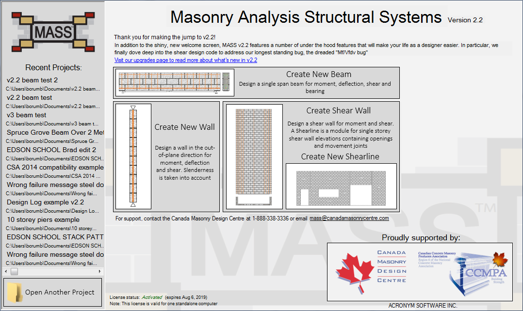
Figure 1-17: Version 2.2 Welcome Screen

Figure 1-18: Welcome Screen for Versions 2.1 and older
Walls and Shear Walls can no longer be designed for negative axial loads
When designing an out-of-plane wall or shear wall, MASS™ now displays an error message with failed design results when the applied axial load drops below zero for any load combination.
![]()
In previous versions, MASS™ would incorrectly design these walls using a factored axial load of 0 kN. To clarify, this does not mean that negative axial loads cannot be applied. An uplift force such as wind uplift can be applied and will be correctly taken into account throughout the entire design process. When this uplift force exceeds all other applied axial loads, the design is no longer within the scope of MASS™.
Shear walls now run a shear design for each unit height along the wall
Shear Walls are now designed for shear at each location along the height of the wall rather than simply choosing a single location and running one design. While it slightly adds to the length of time required to arrive at the final design results, the change was made to address a bug going all the way back to MASS™ Version 1.0 where the moment at the top of the wall was incorrectly used to design the critical section at the base. When MASS™ is calculating vm, the software now uses the actual moment and shear at each location when determining the ratio Mf⁄Vfdv found in CSA S304.1-04: 10.10.1.4. The output was also expanded to show vm results at each location where it is calculated.
Shear Wall support reaction forces are now correctly displayed
Previously, MASS™ would show incorrect vertical reaction forces or no force at all on all shear wall support reaction drawings. This has since been addressed and the support reactions are now correctly displayed. It should be noted that this bug was only a display issue and had no effect on design calculations.
Bond Beams are now displayed in the top course of shear walls
MASS™ now displays bond beams placed in the top course of shear walls designed for shear in accordance with CSA S304.1-04: 10.15.1.3(d) whenever bond beams are required. Previously, MASS™ would display only the bars placed along the height of the wall to satisfy spacing alone without ensuring that one would be placed within the top course. This change only concerns the shear wall drawing and has no effect on design calculations.
Correct f’m value now displayed in Simplified Moment Results for Walls designed for moment and deflection
For out-of-plane walls designed for moment and deflection, the correct f’m value is now displayed in the Simplified Moment Results window. Previously, f’m grouted was shown for all results, regardless of whether the grouted or hollow masonry assemblage strength was used in calculations.
Project files created using MASS™ Version 1.0 are now opened correctly
Previously in MASS™ Version 2.1, there was a bug where many project files created in Version 1.0 could not be opened. This has been addressed for Version 2.2.
Printer options can be changed when printing MASS™ drawings
Specifically for MASS™ drawings, only the default printer could be used in Versions 2.1 and 2.0. This has been addressed for Version 2.2.
Version 2.1 List of Changes
Released May of 2015, Version 2.1 added fire resistance ratings, improved shearline drawings, improved the stability of the custom masonry unit database, as well as addressing other bugs found in Version 2.0.
Fire Resistance Ratings
Fire Resistance Ratings added to Wall and Shear Wall design results
MASS™ Version 2.1 now determines the fire resistance rating for all out of plane wall and shear wall designs based on the equivalent thickness method in the National Building Code. These results can be found in the ‘Simplified Wall Properties’ results tab.
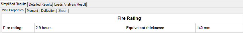
Figure 1-19: Fire Resistance Rating output in results window
Note that even a single, ungrouted cell will result in the assemblage’s fire resistance rating being the same as an entire hollow wall. If units containing a concrete other than “Type S” are used then this can be taken advantage of by changing the unit concrete type within the masonry unit database editor.
User Interface
Drawing Layers combined to optimize resources
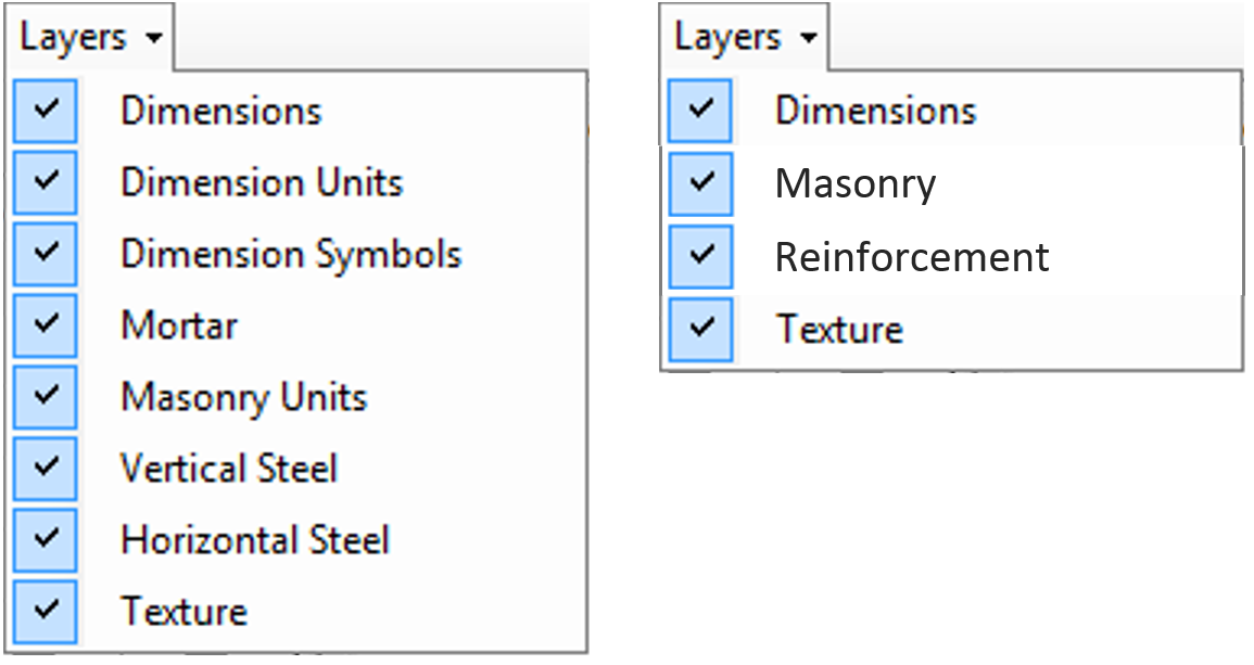 Figure 1-20: a) Version 2.0 drawing layers and b) Version 2.1 Drawing layers
The layers for Dimensions, Dimension Units, and Dimension Symbols have all been combined into what is now simply the Dimensions layer. The Vertical Steel and Horizontal Steel have been combined into what is now the Reinforcement layer. The Mortar and Masonry Units layers have been combined into what is now the Masonry layer. These layers have been combined to reduce memory usage and improve resource efficiency.
Zoom setting improved to accommodate larger designs
The maximum zoom level has been increased to 500% from the previous 250% in order to make it easier to use the drawing window when creating larger shearlines.
Be advised that while this change has been tested on a large variety of computer systems ranging from powerful to modest, it is possible that memory errors could occur. Crashes were observed in some cases for screens with resolutions exceeding 1920 by 1200 pixels. If this occurs, the MASS™ project can be saved and reopened, preventing any work from being lost.
Shearline Drawing Improvements
Reinforcement added to shearline drawings
Once a shearline has been designed, the horizontal and vertical reinforcement now appears on the drawing, in addition to seeing the reinforcement results in the Pier Design Summary results tab.
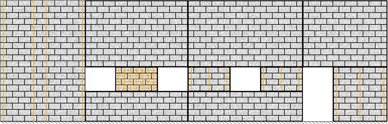
Figure 1-21: Vertical and horizontal reinforcement added to shearline drawing
Pier labels added to shearline drawings
Instead of having to select the various selectable elements within the Panel Properties input tab to see their location within a shearline, labels have been added to the drawings.
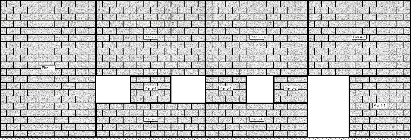
Figure 1-22: Pier labels drawn on the centre of each pier
These labels can be enabled and disabled using the Layers dropdown menu:
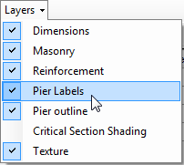
Figure 1-23: Pier Labels Layer
Critical Section Shading added to shearline drawing
A shading layer has been added to shearline drawings which adds a fast and easy to read visual representation of how close each pier is to being loaded to maximum capacity. Green shades indicate that a pier passes both moment and shear design while red shades indicate failure. Darker shades help identify piers that have higher Mf/Mr or Vf/Vr ratios.
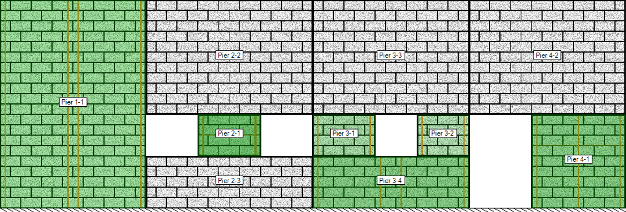
Figure 1-24: Pier elements shaded in green pass both moment and shear design
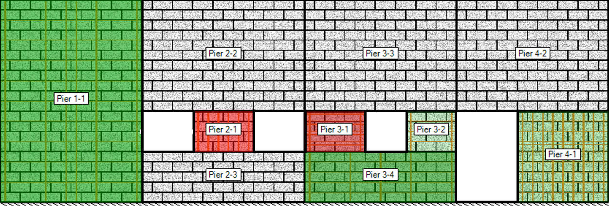
Figure 1-25: Pier elements shaded in red have failed either moment or shear design
By default, this layer is turned off but it can be enabled by selecting the Critical Section Shading drawing layer to be displayed:
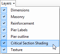
Figure 1-26: Critical Section Shading layer
Pier Outline moved to its own shearline drawing layer
The solid, black outlines of each pier element have been moved to their own drawing layer
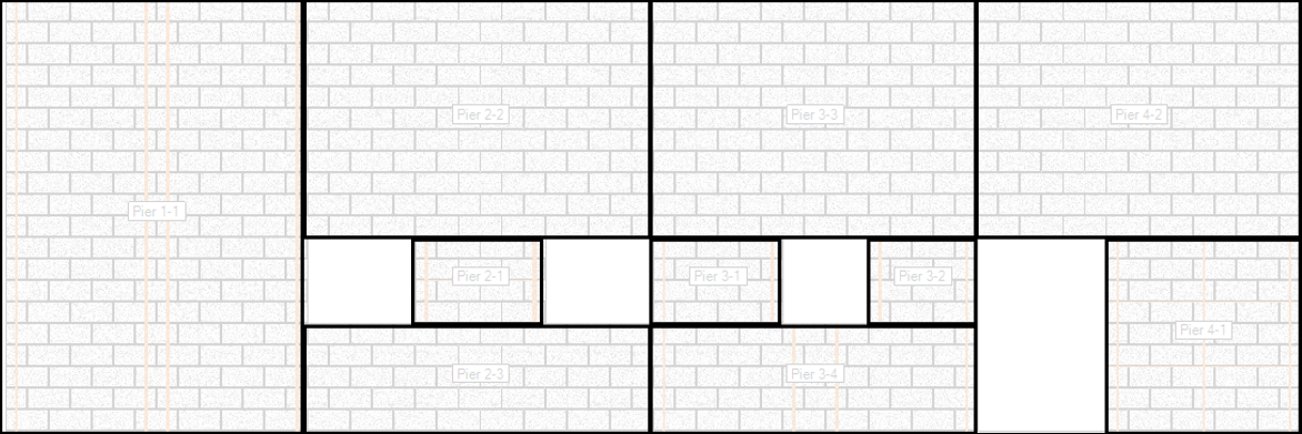
Figure 1-27: a)Pier outlines, b) layer selection
Masonry Unit Database
An improved and optimized masonry unit database is one of the more significant changes in MASS™ Version 2.1.
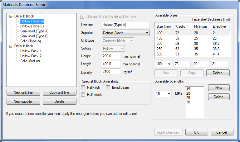
Figure 1-28: Version 2.0 and earlier masonry unit database editor
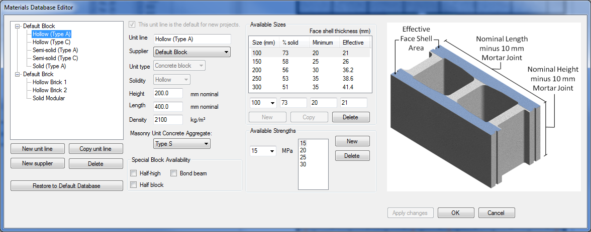
Figure 1-29: New database editor in Version 2.1
Most of the improvements addressed the way information was stored and retrieved for stability reasons. However, there are several observable differences listed below:
Masonry unit concrete type property added
In order to determine the fire resistance rating of an out of plane wall or shear wall, masonry unit concrete type was added to the database as a customizable property. The default value for all units is Type S however units with other specified concrete types can be used in determining fire resistance ratings.
“Restore to Default Database” function added
The Restore to Default Database function was added to quickly restore the program defaults. Be advised that all changes to the database will be lost. Many stability issues in the database were caused by making changes to the default units which would cause conflicts elsewhere in the software so this was added to easily resolve those issues.
Diagram added for each concrete masonry unit type
For all concrete unit types (hollow, semi-solid, and solid), a diagram has been added to the right side of the database editor window to illustrate how the unit geometry inputs are recognized by the program. This was added to clarify and reinforce the concept that each of the nominal dimensions include one 10mm mortar joint. For example, a 25cm unit is actually only 240mm thick.
Existing MASS™ Modules
Slender wall design provisions and yielding requirements
MASS™ displays passing design results for walls where one of grout included or grout ignored analysis includes yielding tension reinforcement and has a moment resistance that is greater than the factored moment including slenderness effects. Previously, if the primary tension reinforcement did not yield for either the grout included or grout ignored analysis, the entire section fails without checking to see if the other method would provide an acceptable design.
Load application bugs
Previous assemblage changes could result in the moment design option being disabled. In particular, with the shear wall module when changing the height after applying axial loads to the top of the wall.
Out of plane line loads unit change
For simplicity, line loads applied to an out of plane wall expressed using imperial units (lbs/ft or kips/ft) have been changed to lb/ft2 and kip/ft2 respectively. These line loads have been expressed using the force per length convention in order to reinforce the concept of designing a unit section of wall. In the case of metric loads, the conversion from a pressure to a line load would not change due to a 1m design strip. In the case of imperial loads, each pressure value was previously required to be multiplied by 3.28 ft/m to convert from a lb/ft2 load to how MASS™ would accept it in the form of lb/ft per 1m length of wall. While this does introduce an inconsistency in the user interface, NMDP felt that the benefits of this change outweigh the drawbacks. MASS™ immediately converts all loads using imperial units into SI units prior to performing any design calculations so if there is any question as to which load is actually being designed for, it is recommended that loads be applied using the default metric selections. In summary, the following line loads are converted by MASS™ to 1kN/m when applied to a 1m length of wall: 1000 N/m, 20.9 lb/ft2, 0.0209 kip/ft2
Shear Wall height and total height synchronization bug fixed
There was an issue with the height/total height functionality where it was possible to input a total height value less than the assemblage height value. This has been corrected and when the height is increased above the total height, the total height will automatically change along with the height. The height will also automatically be reduced if a lower total height value is entered.
Minimum clearances warning message added
A new warning message has been added to MASS™ when designing reinforced walls and shear walls to alert the user that reinforcement is unable to be placed within the wall since the user specified minimum side cover is either less than the code minimum value of the face shell thickness plus 13mm or too large for reinforcement to fit within the wall.
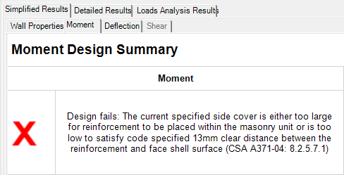
Figure 1-30: Added minimum clearances failure message
Slenderness results not shown for walls with 2 bars/cell bug fixed
Previously for walls containing 2 bars/cell, all results beneath the reinforcement summary within the simplified moment results tab would not be displayed. This had no effect on any calculations or designs and has been fixed in MASS™ Version 2.1.
Activations
MASS™ now remains activated when computer components or operating system are upgraded
A new method is used to distinguish and differentiate computers using various hardware and software indicators. There have been many users requesting re-activations when their computer are incrementally upgraded and this change is aimed at reducing these situations. This change does not affect current activations. If MASS™ was activated using Version 2.0 or older, MASS™ will remain activated in Version 2.1. A new output was added to the “License status:” field in the activation window explaining that a license is not valid when expired.
Printing
Browser compatibility crash fixed
Internet explorer is no longer the only internet browser that is able to print results. The default web browser used for opening other web links is now also used to render, display, and print results. Previously, Internet explorer was the only supported browser for this task, resulting in compatibility crashes. This change has been tested using both Chrome and Firefox.
The user interface has been updated to make it clearer to the user how to select drawing/results/all results for printing. The Print option under the main menu has been updated from “Print” to show “Export for print” with a dropdown menu allowing the user to select from printing the currently displayed drawing, currently displayed results or a compilation of every results tab.

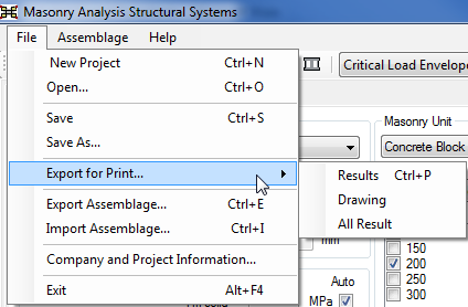
Figure 1-31: a) Print menu in Versions 2.0 and older and b) print menu in Version 2.1
Software Updates
Check for updates windows added
A Check for Updates screen was added under the Help menu to make it easy to know which version of MASS™ is running as well as check to see if a new version is available. This requires a working internet connection.
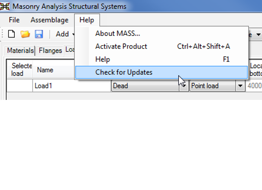
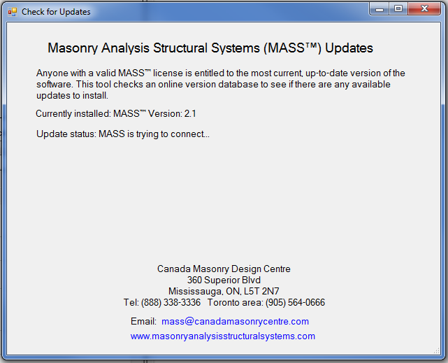
Figure 1-32: a) Check for Updates menu option and b) Updates screen establishing connection
If a newer version of MASS™ is available then a link to the MASS™ download page is displayed with information on accessing the download. Otherwise, a message is displayed alerting the user that they are running the most up to date version of MASS™.
Version 2.0 List of Changes
Released June of 2014, MASS™ Version 2.0 introduced an all-new Shearline module, allowing users to draw an elevation with openings and movement joints, distribute loads around them, and then designs individual pier elements as shear walls. In addition to the shearline module, multiple changes have been made to the existing MASS™ software components.
Existing MASS™ Modules
Slender cantilever walls design provisions
Walls with fixed base support and no top support (cantilever) that are classified as slender reinforced walls (kh/t greater than 30) can now be successfully designed in MASS Version 2.0, provided that all other design criteria are met. Previously, all slender reinforced walls needed to have pinned supports at the top and bottom of the wall, in accordance with CSA 304.1-04: 10.7.4.6.3. The intent of 10.7.4.6.3 is fixed base end condition is taken into account by using the k=2 factor.
Horizontal reinforcement limits for seismic shear walls
Shear walls with a seismic hazard index greater than or equal to 0.35 now use the product of the wall thickness and height when calculating the gross cross-sectional area of masonry, Ag, used in calculating the horizontal reinforcement limits. Previously, Ag, was calculated using the horizontal cross section and used for both vertical and horizontal reinforcement limits which resulted in excessive horizontal reinforcement for squat shear walls and insufficient horizontal reinforcement for non-squat walls.
Masonry unit web % values adjusted for block size
MASS now uses the correct % values from A165.1 Table 3 when calculating the width of masonry used for the factored out of plane shear resistance. Previously, all masonry unit sizes incorrectly used the same % value.
Correction to out of plane shear resistance equation for partially grouted walls
The out-of-plane factored shear resistance equation has been modified to exclude masonry unit’s webs that do not lie within the compression zone for partially grouted walls where the reinforcement spacing exceeds 4 times the wall thickness.
Shear wall simplified results display of cell-by-cell results
The Simplified Moment Results tab now shows cell-by-cell results after the shear design stage has been performed. Previously, cell-by-cell results would be cleared and never restored for shear walls if the design was governed by shear.
Moment arm reduction for low aspect ratio (squat) shear walls
Shear walls with height-to-length ratios less than 1.0 now use the total height when calculating the moment arm reduction between the compression zone and the tensile reinforcement. Previously, the height of the shear wall element rather than the total height of the wall was used when calculating this reduction.
Shear Walls failing in sliding shear display an updated message
A new failure message reading:
- Design fails: The factored shear exceeds the sliding shear resistance because it has insufficient vertical reinforcement area. To increase the sliding shear strength, increase the vertical steel in the moment design using larger bars or reduced spacings. Refer to CSA S304.1-04: 10.10.4.2.
This was added to alert the user that increasing horizontal steel does not address sliding shear failure and is specifically triggered when a vertically reinforced shear wall passes diagonal shear and fails sliding shear.
Version 1.1 List of Changes
Released January of 2012, Version 1.1 was released to address 40 bugs that were found since the release of MASS™ Version 1.0.
Beams
Factored compression force in masonry calculation for beams with tied compression reinforcement (B1)
The factored compression force in masonry, Cm, calculation for beams with tied compression reinforcement was corrected to take into account the reduction of masonry area from the compression reinforcement. Previously, the equation displayed in the Detailed Moment Results correctly showed this reduction; however it was not used in calculating the displayed result or the value used in design.
Displayed factored shear resistance result for beams failing in shear without shear reinforcement (B2)
In the Simplified and Detailed Shear Results, the factored shear resistance, Vr, displayed result for a failed shear design of beams without shear reinforcement was corrected. Previously, the displayed result was incorrectly showing the value of Vr = Vm + Vs, max rather than the correct value of Vr = 0.5Vm. This affected the displayed result only and not the value used in design.
Placing stirrups in beams with d/2 less than single cell width (B3)
A check was added when changing beam height to ensure stirrups at a maximum spacing of d/2 are able to be placed. If the maximum spacing as specified in CSA S304.1-04 11.3.4.8 is less than the width of a single cell, stirrups are unable to be placed and the “single leg” and “double leg” configuration options are disabled. Previously, after performing shear design where stirrups are manually required by the user (deselecting “none” configuration for vertical steel) and changing the beam height to a value less than d/2, stirrups were displayed even though maximum spacing requirements were not met. This affected the displayed drawings and Simplified Shear Results only and not the factored shear resistance displayed or used in design.
Beam drawing course layout when opening previously saved files (B9)
Beams are now drawn with the same course layout when a saved file is opened as when it was originally saved. Users are able to modify a beam such that the bottom course starts with a half-unit on the left end of the beam drawing. Previously, when a saved file was opened it would always be drawn with the bottom course starting with a full unit. This affects only the beam drawing and has no impact on design.
Deep beam error message (B10)
A beam is no longer identified as a deep beam in accordance with CSA S304.1-04 11.2.7 until the height and the length or clear span of the beam have been entered. Previously, when creating a new beam and entering a value for height prior to entering a value for length or clear span, an error message related to deep beam design was incorrectly displayed.
Minimum threshold for factored moments used in moment design (B12)
The program now applies a minimum threshold of +/- 0.01 kNm before factored moments result in positive or negative moment design. Previously, very large loads could result in small, false moments due to rounding errors, triggering moment design in the opposite direction.
Walls
Factored shear resistance or maximum shear resistance not displayed (W1)
The result for factored shear resistance, Vr, and maximum shear resistance, Vr, max, are now both displayed in Simplified Shear Results, regardless of which value governs the design. Previously, only the result for the value governing the design (Vr or Vr, max) was displayed while the other result was left blank.
Shear design failure message reference change (W2)
The failure message displayed for walls failing in shear design now correctly references CSA S304 1-04 10.10.2 for out of plane shear resistance in the shear design summary of Simplified Shear Results. Previously, the failure message referenced CSA S304.1-04 10.10.1 for in-plane shear.
Slender unreinforced walls failure message (W3)
Unreinforced walls with a slenderness ratio, kh/t, greater than 30 now display the following failure message in Simplified Moment Results: “Design fails: The slenderness ratio kh/t for unreinforced walls shall not exceed 30, in accordance with CSA S304.1-04 7.7.5.2. Walls with a slenderness ratio greater than 30 must be reinforced in accordance with CSA S304.1-04 10.7.3.3.3”. Previously, the following incorrect failure message for maximum axial load was displayed: “Design fails: The current set of selections results in a factored axial load resistance that exceeds the maximum allowed as defined by CSA S304.1-04: 10.4.1. Please select a new masonry unit.”
Crash fixed for unreinforced wall deflection drawings (W4)
Users are now able to select load combinations other than the critical load combination from the drop down list for the deflection drawing of unreinforced walls. Previously, when the user selected a load combination other than the critical load combination the program would crash.
Text added for deflection drawings of unreinforced walls (W4)
When designing with unreinforced masonry, the program now displays the following message on the Deflection drawing for all load cases “There is no deflection design for unreinforced walls”. Previously, a deflection drawing would be displayed showing no deflected shape.
Wind load importance factor now used in calculating the deflection of walls (W5)
The importance factor of 0.75 for serviceability limit states (SLS) is now correctly applied to wind loads within loads analysis used in determining service load deflection. Previously, the correct importance factor was displayed properly in all serviceability load combinations; however, a value of 1.0 was used by the loads analysis for the service wind loads in calculating the deflection. This resulted in a larger service wind load deflection in Version 1.0 but did not affect moment or shear design.
Sliding shear variable, Auc, not displayed (W6)
Detailed Shear Results for factored sliding shear resistance of unreinforced masonry now displays all the all information for the uncracked cross-sectional area, Auc. Previously, this line was omitted.
Shear resistance variable, Ae, displayed equation correction (W6)
Detailed Shear Results for unreinforced hollow walls now display beff x 2tf as the equation for effective area, Ae. Previously, the equation was incorrectly displayed as bw, eff x t. This affected the displayed equation and had no effect on the calculated result.
Additional information added to Detailed Shear Results for factored sliding shear resistance (W7)
Additional lines of information were added within Detailed Shear Results for factored sliding shear resistance of reinforced masonry. Previously, only cell incrementation, hi, and coefficient of friction, µ, were displayed with no additional information showing how the factored sliding shear resistance was calculated. This only affected information displayed in Detailed Shear Results and had no effect on the calculation of factored sliding shear resistance.
Change to the effective stiffness, (EI)eff, when grout is ignored (W8)
For reinforced walls where the critical Mf and Pf are in the area of the interaction diagram where grout is ignored, 0.25EI0 is now used for the upper bound of effective stiffness, (EI)eff. Previously, the upper limit for this case was incorrectly placed at (EI)eff = 0.4EI0 which can only be used for unreinforced masonry. This resulted in smaller than expected moment magnification for these uncommon cases of Mf and Pf.
Factored moment resistance result displayed under Simplified Moment Results when factored axial load for critical load combination is greater than Pequal1 (W9)
Factored moment resistance, Mr, is now displayed in the Simplified Moment Results for hollow unreinforced walls when the factored axial load, Pf, for the critical load combination is greater than the factored axial load at which the factored tensile moment resistance is equal to the factored compressive moment resistance using uncracked section properties, Pequal1. Previously, no value was displayed for Mr when Pf was greater than Pequal1. This affected the displayed result only and not the value used in design.
Detailed Moment Results now displays correct results for unreinforced masonry walls with a factored moment resistance governed by an eccentricity of t/3 (W9)
For unreinforced walls where the critical load combination has a factored axial load, Pf, within the area of the interaction diagram in which the moment resistance, Mr, is governed by the limiting eccentricity of t/3, the correct result for Pr1, Cm1, Acomp and c are now displayed under Detailed Moment Results. Previously, these variables were listed with correct values used in calculation but the displayed result was 0.0. This affected the displayed result only and not the value used in design.
Factored dead load moment used in βd now calculated using correct load combination (W10)
In the calculation of the ratio of factored dead load moment to total factored moment, βd, the factored dead load moment is now calculated using the correct load combination. Previously, an unrealistically large value of βd was calculated for load combination 1: 1.4D only (this load combination has been changed to 1.4D + 1.5Ds, see 33) since Dead and Soil load types were used in the factored dead load moment calculation but only the Dead load type was used in the total factored moment calculation. For load combination 1: 1.4D, this resulted in a factored dead load moment that was significantly larger than the total factored moment when a Soil load type (now called Vertical Soil, see 34) was applied laterally to the wall.
Line load arrowhead placement (W11)
Arrowheads drawn on a line load not extending to the top edge of a wall are now properly placed at the extent of the line load. Previously, the upper arrowhead of the line load was incorrectly drawn above the top of the wall.
Correction to displayed equations for moment resistance of unreinforced masonry in Detailed Moment Results (W12)
Moment resistance equations for cracked section analysis (Mr1, Mr2) displayed in Detailed Moment Results are now correctly displayed. Previously, the result was correct when using cracked section analysis; however, the equation displayed was for the Mequal line drawn vertically starting at Pequal and intersecting the limiting eccentricity (t/3) line. In addition, where critical factored axial load, Pf, was located within the range of the Mequal line, no equations or results were displayed. This affected the displayed equation and result but had no effect on the calculation of factored moment resistance.
Correction to the minimum vertical reinforcement area for walls with seismic hazard index greater than or equal to 0.35. (SW2)
For walls that require vertical reinforcement and have a seismic hazard index greater than or equal to 0.35, the check for minimum reinforcement area has been changed to correctly calculate the minimum as 0.0013Ag or 0.0013(t × 4t), in accordance with CSA S304.1-04: 10.15.1.1. Previously, the minimum vertical reinforcement area for walls with a seismic hazard index greater than or equal to 0.35 was 0.00067Ag in accordance with CSA S304.1-04: 10.15.2.1. However, walls having a seismic hazard index greater than or equal to 0.35 must be designed as reinforced walls in accordance with CSA S304.1-04: 4.5.1 and since the program only accommodates vertical reinforcement (i.e. walls supported at the top and bottom) to resist the loads, the minimum vertical steel of 0.0013Ag or 0.0013(t × 4t), as described above must be satisfied.
Shear Walls
Correction to equation for effective compressive strength for smeared design (SW1)
The effective compressive strength of the smeared section of masonry between the end zones, f’m, web, eff, is now calculated correctly using only the portion between the end zones. The equation for Csmear in Detailed Moment Results was also corrected to use f’m, web, eff rather than f’m, smear, web when end zones are present. Previously, the effective compressive strength used in determining the factored axial load and moment resistance was based on the entire length of the web, including the endzones. In typical cases where f’m,solid is less than f’m hollow, this resulted in a lower effective compressive strength and a conservative design.
Check added for minimum horizontal reinforcement area for shear walls with a seismic hazard index greater than or equal to 0.35 (SW2)
A check was added for minimum horizontal reinforcement area, Ash, min = 0.00067Ag in accordance with CSA S304.1-04: 10.15.2.2, during shear design for shear walls with a seismic hazard index greater than or equal to 0.35. Previously, this check was not performed.
Shear walls with a seismic hazard index greater than or equal to 0.35 that fail shear design with joint reinforcement configurations set to “none” now display the correct failure message in the Simplified Shear Results: “Design fails: The steel reinforcement does not meet the minimum bar area specified by CSA S304.1-04: 10.15.2.2.”. Previously, the following failure message pertaining to stirrups for beam design was displayed: “Design fails because There is insufficient steel stirrup area and/or bar spacing according to CSA S304.1-04: 11.3.4.7.1,2 and/or: 11.3.4.8”.
Factored shear resistance (steel) result now correctly calculated for seismic hazard index greater than or equal to 0.35 (SW2)
Factored shear resistance (steel) result for shear walls with a seismic hazard index greater than or equal to 0.35 is now correctly calculated within Simplified and Detailed Shear Results. Previously, this result for factored shear resistance (steel), Vr, steel, was always assigned as 0.0. This resulted in a conservative value for factored shear resistance, Vr, neglecting the added resistance from reinforcement for reinforced shear walls with a seismic hazard index greater than or equal to 0.35.
Minimum reinforcement check added for shear walls with seismic hazard index greater than or equal to 0.35. (SW2)
A check was added such that unreinforced masonry shear walls cannot be used when the seismic hazard index is greater than or equal to 0.35, in accordance with CSA S304.1-04 10.15.2. Previously, this check was not performed.
Correction to the minimum vertical reinforcement area for shear walls with seismic hazard index greater than or equal to 0.35. (SW2)
For shear walls that require vertical reinforcement and have a seismic hazard index greater than or equal to 0.35, the check for minimum reinforcement area has been changed to correctly calculate the minimum as 0.0013Ag or 0.0013(bw × 4bw), in accordance with CSA S304.1-04: 10.15.1.1. Previously, the minimum vertical reinforcement area for shear walls with a seismic hazard index greater than or equal to 0.35 was 0.00067Ag in accordance with CSA S304.1-04: 10.15.2.1. However, shear walls having a seismic hazard index greater than or equal to 0.35 must be designed as reinforced walls in accordance with CSA S304.1-04: 4.5.1 and since they will require vertical reinforcement to resist the loads, the minimum vertical steel of 0.0013Ag or 0.0013(bw × 4bw), as described above governs.
Top course units are highlighted when non-modular size is specified (SW3)
Top course units with heights between 101mm and 189mm are now correctly highlighted to alert the user that a non-modular size has been specified. Previously, units of this height would not be highlighted.
Moment design failures caused by shear design (SW4)
Shear wall configurations that are governed by shear design will no longer cause a moment design failure due to minimum vertical reinforcement requirements. Upon completion of a successful moment design and initiation of shear design, the program determines the shear resistance for the successful moment configuration and will continue to cycle through available configurations until there is a successful shear design or no solution can be found. Where shear design has changed the configuration by increasing the block size and causes a failed moment design due to minimum vertical reinforcement requirements, the program will now revert to the previous successful moment design configuration and indicate a failed shear design. Previously, a shear wall could initially satisfy moment design and then show a failed moment design due to minimum vertical reinforcement as a result of an increase in block size during shear design.
Loads Analysis
A warning message was added to alert the user that one or more loads are applied beyond the extent of the assemblage (LA1)
A warning message was added to alert the user that a reduction in beam length or wall height has caused one or more applied loads to be applied beyond the extent of the assemblage. Previously, the load would extend beyond the assemblage and the analysis would only include the portion of load applied to the assemblage.
Correction to unit conversion for applied loads (LA2)
Magnitudes of applied loads are now properly converted between metric and imperial load units. Previously, an incorrect conversion factor was applied.
Self-weight on reaction diagrams (LA3)
Factored self-weight is now included in the vertical reaction force value displayed on the reactions drawing for walls and shear walls. Previously, the vertical reaction force value for walls and shear walls would include applied axial forces only.
Change to load combinations for dead loads only (including soil)
The program now implements the load combination 1.4D + 1.5Ds, as its only “dead-only” load combination, where Ds is the vertical load due to earth and soil. Previously, two load combinations were implemented (1.4D and 1.25D + 1.5Ds) which may have created an unconservative design when dead-only load combination including Ds loads was critical. This change was prompted by a clarification that appeared in 4.1.3.2 (9) of NBCC 2010.
Clarification of earth and soil loads
The dead load due to soil, superimposed earth, plants and trees, Ds, referenced in CSA S304.1-04: 4.2.2.2 (5) has been renamed from Soil to Vertical Soil. The effects due to lateral earth pressure including groundwater, H, referenced in CSA S304.1-04: 4.2.2.2 (1) has been renamed from Hydrostatic to Lateral Earth. This was done to clarify the application of these load types.
Miscellaneous
User agreement window formatted to fit all text (B4)
The user agreement window has been reformatted to display all text above the text window containing the “Software License Agreement”. Previously, the text was truncated and the following text was missing: “…agree, click “Cancel”.”
Welcome screen changed to handle different Windows display settings (B6)
The formatting for the welcome screen has been changed to handle different Windows display settings and font size so that the navigation button locations matched the icon locations. Previously, a change in Windows display settings may have caused navigation buttons to be placed in the incorrect location.
Confirmation pop-up message added when user form is completed (B7)
During the activation process, a confirmation pop-up message now appears upon successful completion of the user form. Previously, a notification was displayed at the bottom of the completed form that was typically out of sight.
Installation Folder name changes (B11)
File and folder names were changed in the installation folder. The Application file “Mass” was changed to “MASS”, the folder “MaterialsDatabase” was renamed to “Material Unit Database”, and the icon file “MassIcon.ico” was renamed to “MASSIcon.ico”.
Correction to program name in printed results title
In the title of printed results, “Masonry Analysis Structural System” was changed to “Masonry Analysis Structural Systems”.
Continue Reading: Getting to Know MASS