

What’s new in Version 4.0?
Many of the notable changes in MASS summed up in one page
Contents
- General Interface Changes
- Beams
- Secondary Minimum Steel Check
- Cracking Check added to Serviceability
- New Tied Steel Confinement Check
- Larger Spacings for Deep Shear Spans
- Stirrup selections highlighted bug
- Deflection results shown for failed designs
- Beam Summary Display Settings
- Tension steel default side cover change
- Intermediate steel automatic placement
- Out-of-Plane Walls
- Shear Walls
The biggest changes added to MASS Version 4.0 are the addition of a new Multi-Storey shear wall assemblage, the addition of boundary elements to shear wall design, as well as expanding the scope of seismic considerations.
Looking for changes between older versions? The full change log is available here.
A full section decided to the design of multi-storey shear walls using MASS has been added to this website and is available for reading here. More specifically, a section on boundary elements can be found here and a seismic tab outline can be found here.
The remaining changes that do not fit within the aforementioned categories can be found below – divided by assemblage type or whether they are a change to the overall user interface.
Note: An updated installation release was posted on Oct 19th, 2020, replacing the initial Version 4.0 release to address a bug related to the activation process as well as unprompted computer restarts when installing the Microsoft C++ dependency.
General Interface Changes
This section covers the major changes that do not relate to just one masonry assemblage type.
Activation Screen and Process
The activation screen as well as what information is shown upon opening has been changed to simplify the process.
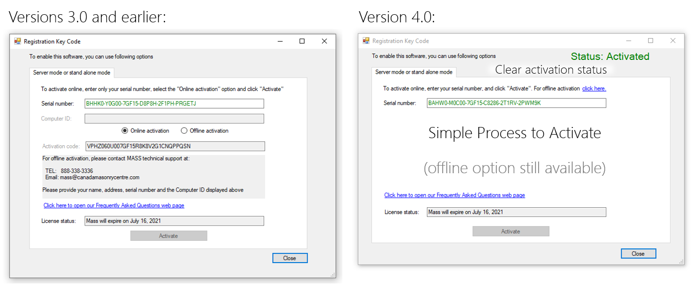
A large, coloured text label has been added to the top right area of the window to indicate clearly whether a license is currently activated or not. Any offline information is not shown in order to make it immediately clear that only the serial number is needed to start the process, only becoming visible after entering in that serial number.
Online Activation Access Restored
As a result of the activation server hosting location being moved (with CMDC being notified retroactively and not ahead of time), the connection location used by the software no longer pointed to the right location. This has been written about in more detail here. MASS is now able to perform an online activation for those with computers that do not restrict the software’s permissions.
Drawing Zoom and Pan Change
Users can now scroll using the mouse wheel or track pad to zoom in or out on all MASS drawings. While the scroll bars along the right sides of the screen can still be used to pan around the drawing area after zooming in, the ability to hold the right mouse button has been added to Version 4.0.
A feature spotlight post linked here demonstrates this new functionality.
(Note that originally the left mouse button was used but this interfered with shearline input and interaction diagram results display)
Scientific notation Added to Results
Values larger than 7 digits (10,000,000) will now default to scientific notation in order to make them easier to read and compare. Previously, these were shown in full, resulting in effective wall stiffnesses that could be 14 digits long and difficult to read or compare.
Load names no longer trigger a crash
Previously, loads added to beams, walls, and shear walls which were manually renamed to anything containing the text string sequence “Load” would trigger a crash upon the addition of a subsequent load. This was a result of how new loads were named and has been addressed with the release of Version 4.0.
Interior Clearance based on Grout Selection
MASS not will adjust the minimum interior clearance between the outermost edge of any reinforcing bar and any interior masonry surface (typically the inside face of a face shell). Previously, the larger 13mm was used in all cases which corresponds to coarse grout. However, since a grout type input was added to MASS as part of the shear design changes introduced by the release of CSA S304-14, this clearance can be changed to 6mm through the use of a fine grout.
Right clicking on secondary monitor
Previously, when MASS had been moved from the primary monitor across the desktop for use in a secondary monitor, right clicking on an assemblage in the bottom toolbar would result in the contextual click menu appearing in the correct relative location within the wrong monitor. This has been fixed in MASS Version 4.0.
Reinforcement display labels
To match building code and CSA Standards convention, the text labels for reinforcement bar sizes has been changed to the new format of “_M”. For example, what was formerly referred to as a “No. 15 bar” is now displayed as a “15M bar”.
Beams
This section covers the changes to MASS Version 4.0 having to do with beam designs.
Secondary Minimum Steel Check
For some beam designs, a fallback check was added for cases where the beam does not meet the minimum steel requirements outlined in CSA S304-14: 11.2.3.1. In such cases, before failing and incrementing properties to the next cross section in the design, an additional check is performed based on CSA S304-14: 11.2.3.2 which can be used in lieu of the first check.
Note: This change has been implemented exclusively for beams with only a single layer of tension reinforcement (no intermediate or compression steel). This decision was made to keep the derived expression simple and also address the key area of small masonry beams with relatively nominal loading (over a doorway for example) which was the reason for implementing this fallback clause.
Cracking Check added to Serviceability
A new serviceability check has been added to MASS to check cracking, as outlined by CSA S304-14. This was previously omitted as it was considered a detailing check which is outside of the scope of MASS. However, this was changed to address the expected increase in lightly reinforced masonry beams designed using MASS as a result of the Minimum Steel change outlined in the item above.
Note: The default exposure setting has been set to Interior as it applies to the large majority of designed concrete masonry beams. It is up to the design expertise of the user to change this for beams with exterior weather exposure if appropriate.
New Tied Steel Confinement Check
A check has been added to the stirrup placement process within shear design to ensure confinement for bars that must be tied. Previously, MASS would allow the user to indicate to the software whether or not to use a bar in compression by selecting the Tied check box. This was because of how moment and shear design are separated into two distinct stages where tied confinement could not be checked before moment design.
Note: this check will place stirrups along the entire length of any tied bars in compression, rather than just for the regions where the bar is in compression.
Larger Spacings for Deep Shear Spans
In Versions 3.0 and earlier, MASS would not permit horizontal reinforcement or stirrup spacings larger than 400mm for deep shear spans. This would be triggered in relatively large beam designs where the space between the top layer of intermediate steel would be further than two courses away from the lowest layer of compression steel. The restriction has been removed in Version 4.0 to permit larger spacings as CSA S304-14: 11.3.6.3 is only applied to strut-and-tie modelling, which is not done within MASS.
Stirrup selections highlighted bug
Previously, MASS would only highlight the successful stirrup configuration used in a beam design if only one option for each section was checked. For example, no properties would be highlighted if both single-legged and double-legged selections were made but the properties would be highlighted if only one of those selections were made. this has been fixed with the release of Version 4.0.
Deflection results shown for failed designs
Previously, MASS would display the successful moment result for beams that passed moment but also failed deflection, making it not immediately obvious why the inputs were not highlighted in green. A change was implemented in Version 4.0 where beams passing moment and failing for deflection will show the failed deflection results.
Beam Summary Display Settings
Upon the completion of bearing design for masonry beams, MASS now shows the Simplified Beam Properties results view, which contains bearing results as well as a summary of all other design stages. Previously, the existing shear results would be shown, making it not immediately obvious that any bearing design work had been completed.
Tension steel default side cover change
The side cover value used for bottom steel in the Minimum clearance section of the beam materials input window has been changed from the original default value of 65mm down to 55mm. While this reduction will leave adequate space between longitudinal tension reinforcing bars and the interior edge of the masonry unit, this value reduction was to allow 15cm unit designs to be shown to the user before immediately moving on to attempting beam designs using 20cm blocks.

The previous value was set with the case of very large units in mind (such as a 30cm unit) but an unfortunate side effect was automatically failing every attempted 15cm design because even just a single 10M bar diameter would be 1mm too large to fit within a space 65mm from each exterior beam face.
Intermediate steel automatic placement
The procedure for placing intermediate steel has been changed to no longer place any additional bars above the bottom third of the beam. Previously, there were cases where more longitudinal bars would be placed than the minimum specified by the CSA Standards.
Out-of-Plane Walls
This section covers the changed implemented in Version 4.0 having exclusively affecting the Wall module.
Deflection results shown for failed designs
Previously, MASS would display the successful moment result for beams that passed moment but also failed deflection, making it not immediately obvious why the inputs were not highlighted in green. A change was implemented in Version 4.0 where walls passing moment and failing for deflection will show the failed deflection results.
Shear Walls
This section outlines the additional changes in Version 4.0 concerning the shear wall module. As mentioned earlier, the change in scope regarding seismic design, boundary elements within cross sections, and multi-storey designs,
Shear Drawings reflect different resistance along height
Previously, the lowest resistance within a shear wall element was plotted along the entire height.
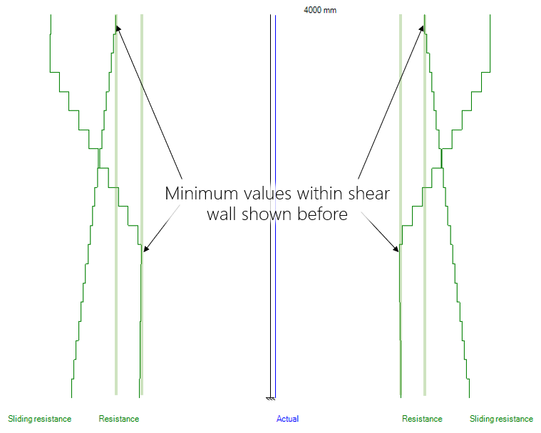
The different resistance values have always been calculated for each course and checked internally, however these varying resistances reflected on the drawings is new to Version 4.0.
Units in flanges can be tied to web
An option has been added to the Flanges tab in the input window for the flange to use the same masonry unit as the web.
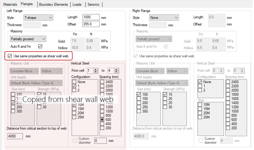
This is useful when the final design of the shear wall is unknown and the user plans to continue with the same unit for both the web and flanges.
Bond Beam Placement Change
Since when bond beams are placed, a bond beam is always placed within the top course of a shear wall element, spacings counted from the bottom of the wall would sometimes result in drawn configurations with bond beams grouted more closely together near the top of the wall.
In Version 4.0, the spacings are now counted from the top bond beam course, resulting in a more even steel distribution over the height of the wall.
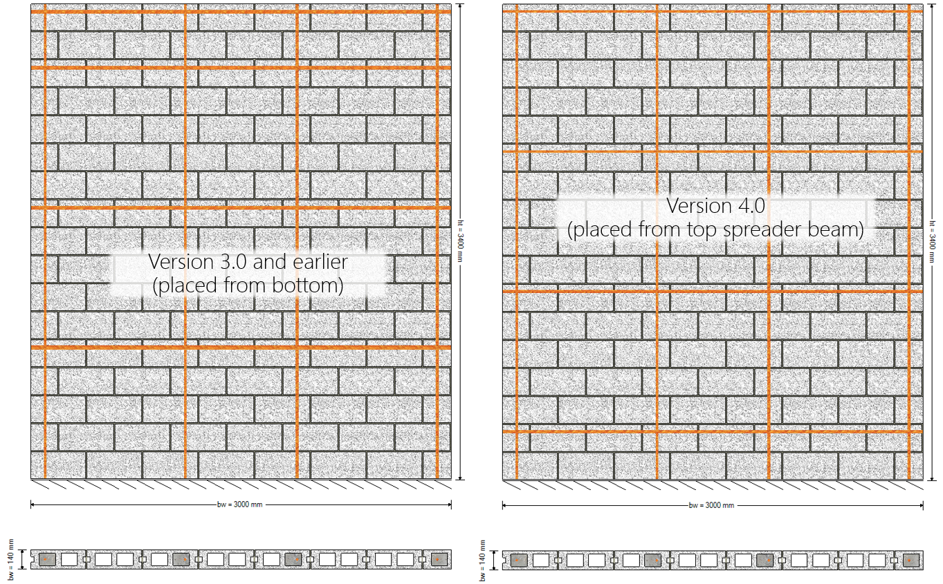
Note that this change is purely cosmetic and does not affect and calculations which reference a single spacing value that remains unchanged.
Fully Grouted Walls from Bond Beams
Shear Wall designs that do not have vertical bars placed in every cell and are partially grouted are now treated as being fully grouted if a horizontal bond beam is placed within every course.

Previously, some checks such as in-plane shear resistance would use a gamma factor corresponding to that of a partially grouted wall, even though the presence of a bond beam in each course would change this factor to reflect a fully grouted wall. This lead to lower than expected shear resistances which in some cases could result in shear walls with too much horizontal steel added for shear design.
Note: self-weight calculations were handled correctly before this change was made, even though the wrong gamma factor had been used.
Total Height changes now trigger redesign
Previously, changing the Total Height for a designed shear wall would not trigger a redesign, leaving the results which corresponded to the Total Height value before then change had been made.
Joint reinforcement corrupt file bug
A long running bug where .masonry14 project files could not be opened has been diagnosed and fixed with the release of MASS Version 4.0. Previously, a saved project file with a specific set of joint reinforcement shear selections would not be able to be reopened after being saved and closed.
Definition of End Zones changed
When the smeared properties is selected, single grouted cells at each end of the shear wall web are no longer designated as end zones and instead considered within the smeared cross section. End zones are no longer identified unless there are at least two consecutive cells at each end of the web.
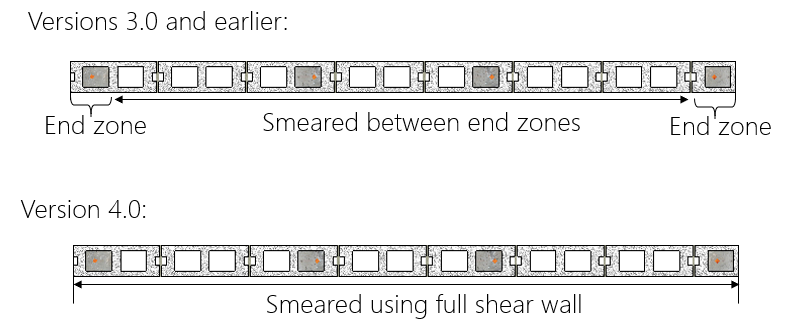
Note: partial cells of at least 10mm are included as part of end zones and can result in one full grouted cell being classified as an end zone.