

Seismic Tab
Added in MASS Version 4.0, the seismic tab increases the scope of what can be done using MASS
Contents
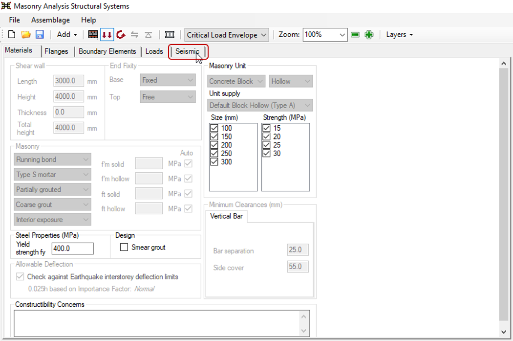
Present in the shear wall, shearline, and multi-storey shear wall assemblage modules, the seismic tab contains input fields that must be completed in order to design any shear wall elements that are subjected to an earthquake type load.
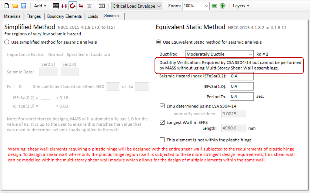
The tab can be found along the top of the input window to the right of the Materials and Loads tab, shown below:
Within the seismic tab, there are two methods of seismic analysis and design that MASS allows for; the Simplified Method and the Equivalent Static Method. These are described at length in the subsections below.
The Simplified Method
New to the 2015 edition of the National Building Code is a simplified method for performing a seismic design on a structure, meant for areas with very low seismic risk. This method was carried forward in the NBCC 2020 as well.
Method Selection
In order to use the Simplified Method, the option must be selected beneath the heading.
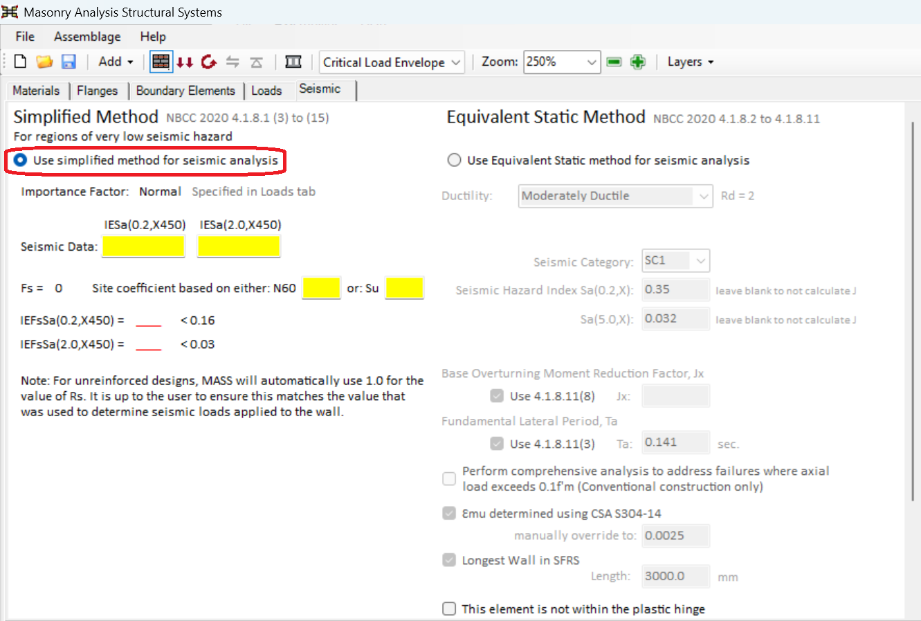 Note that by default, the Equivalent Static Method is selected.
It is up to the professional engineering judgment of the user to determine which method is appropriate. In very general terms, the Simplified Method covers a very narrow range of design situations but offers the opportunity to bypass all of the additional seismic requirements found in Chapter 16 of CSA S304-14.
MASS will inform the user whether sufficient inputs have been entered as well as whether or not the shear wall qualifies for design using the Simplified Method. Applicability is determined by the software based on the criteria outlined in the building code only to the extent of what can be evaluated based on the inputs. For example, accidental torsional effects referenced in NBCC 2020: 4.1.8.1(9) must be factored into the loads entered by the user at the Loads Input design stage so there is no way for MASS to handle this automatically.
Earthquake Importance Factor, IE
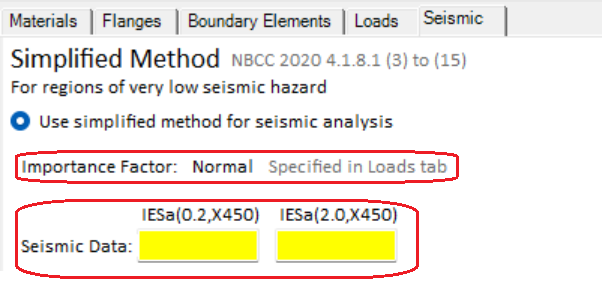
As indicated in the seismic tab, the Importance Factor can be specified and changed in the loads input tab. However, it appears as an output for quick user reference only. The corresponding value for the importance category must be manually multiplied with the damped spectral acceleration values for the input fields for ‘Seismic data:’
Damped Spectral Accelerations, Sa(T,X)
Beneath the importance category in the seismic tab input window is where the 5% damped spectral response acceleration (as a ratio of gravitational acceleration), at a period ‘T’ for the site designation ‘X’ can be found. Since these accelerations corresponding to a period of 0.2,and 2.0 seconds are needed for MASS to determine whether the Simplified Method can be used, they are required inputs by the user.
These values are entered manually by the user and are based on the climatic and seismic hazard data from the relevant authority having jurisdiction or Appendix C of NBCC, in accordance with subsection 1.1.3.
A seismic design cannot be performed if a valid numerical value has not been entered.
NRC offers a helpful tool online that can be found by clicking here. Use at the users professional engineering judgment and ensure the correct code edition has been selected from the drop down list.
 Site Coefficient, Fs
The site coefficient is another required variable that must be calculated in order for MASS to determine whether the Simplified Method can be used for a shear wall design. The value of Fs is based on one of two possible input values:
N60: Average undrained standard penetration test resistance correcting for 60% efficiency, measured in number of blows.
su: Average undrained shear strength of the top 30m of soil, measured in kPa.
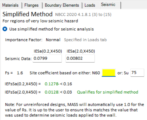
As soon as one of these two input fields have been filled with a valid numerical value, the site coefficient is shown to the left where it previously appeared blank.
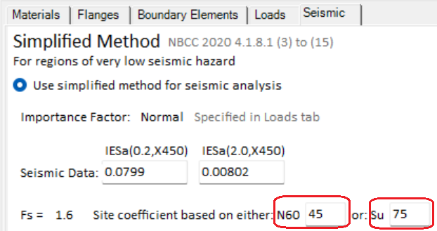 Note: Only one of these two fields needs to be input to run a design, this image is for illustrative purposes.
Site coefficient is calculated by MASS in accordance with NBCC 2020: 4.1.8.1(2) and can also be found in the Detailed Seismic Results tab upon completion of a design.
Determining Applicability
Once all three of importance factor, spectral acceleration response, and site coefficient are known, MASS determines whether the design qualifies for the Simplified Method to be used. Successfully qualifying designs are indicated with green text whereas designs that do not qualify are shown with red text, shown below:
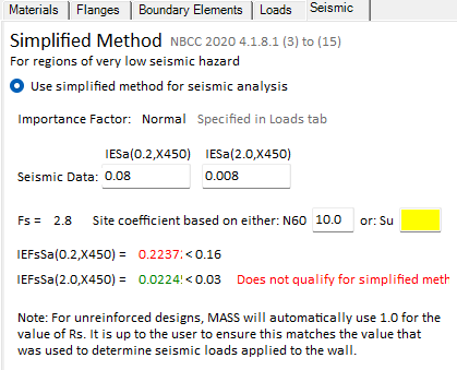 Qualification is determined based upon NBCC 2020: 4.1.8.1(2). If a design is not deemed by MASS to be applicable and the user opts to continue with the design, they will be shown a failure message at the moment and deflection design stage, indicating that they must go back and switch to using the equivalent static method.
Equivalent Static Method
Referred to as the Equivalent Static Force Procedure in the National Building Code, this method offers significant flexibility and does not come with the same exclusions used for the Simplified Method. Any combination of importance factor, spectral response acceleration, and site class can be designed for without first having to satisfy the criteria of NBCC 2020 4.1.8.1 (2). As a result, there are additional seismic requirements in CSA S304-14:16 that must be considered by the end user which MASS designs for as well.
Method Selection
The Equivalent Static Method is selected by default to be used when an earthquake load has been applied to a shear wall. Similar to choosing the selecting Simplified Method, the user can check the bubble just beneath the Equivalent Static Method heading, shown below:
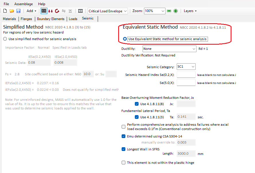 Once selected, all Simplified Method options are disabled (greyed out) and a number of inputs become available, outlined in the subsections below.
Ductility, Rd
Each seismic force resisting system (SFRS) classification has a corresponding value of Rd which affects the seismic design process. The ductility selection is up to the professional engineering judgement of the user.
Note: Since the magnitude of earthquake loads is a function of ductility, it is important that the selected ductility matches what was used to calculate the loads input into the Loads tab.
There are four possible ductility classifications available for design using CSA S304-14:
- None
- Conventional Construction
- Moderately Ductile
- Ductile
Each ductility selection is further explained below:
None, Rd = 1.0
The zero ductility is used for unreinforced masonry (URM) designs where there is no energy dissipation from permanent deformations. All URM shear wall designs attempting to also use Rd > 1.0 will be failed by MASS at the outset of the design process. Shear walls with no ductility subject to seismic loads determined using the equivalent static procedure are designs using CSA S304-14: 16.2.
Conventional Construction, Rd = 1.5
The conventional construction ductility level is the lowest possible ductility selection for reinforced masonry (RM) shear wall designs in CSA S304-14. Although there is less energy dissipation that can be relied upon to reduce unfactored earthquake loads (calculated and entered by the user), there are fewer restrictions and considerations in the CSA Standards compared to moderately ductile and ductile shear walls, explained below.
Moderately Ductile, Rd = 2.0
The moderately ductile designation allows for a further reduction of loading due to the increase in non linear effects compared to conventional construction shear walls. This brings along with it additional code restrictions and design considerations. The biggest change when increasing SFRS ductility to moderately ductile is the requirement of performing a ductility verification as well as detailing a plastic hinge region for shear walls that have an aspect ratio greater than 1. Moderately ductile, squat shear walls are also allowed to be designed and while they do not require a ductility verification or plastic hinge region, they are subject to additional CSA restrictions.
Ductile, Rd = 3.0
The ductile classification is the highest available within CSA S304-14 Chapter 16. Squat shear walls are not permitted within this designation and a separate set of design considerations are laid out in the CSA Standards.
The ductility input drop-down is the user’s way of informing the software which clauses in the CSA Standards to apply to a design and it is up to the professional engineering judgment of the user to make this decision.
Seismic Category
There are four possible Seismic Category classifications according to NBCC 2020 noted SC1, SC2, SC3 and SC4.
The user needs to manually select the applicable seismic Category from the drop down list in accordance with Clause 4.1.8.5.(2) and is based on both the Importance Factor of the structure but also the Seismic Hazard Index.
Seismic Categories are used to inform restrictions on various buildings such as height restrictions of clause 4.1.8.9. These restrictions were previously assessed using inputs for Sa(0.2) and Sa(1.0) but the methodology has been updated to match NBCC 2020.
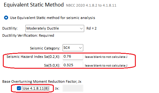
Seismic Hazard Index
Moved from the vertical reinforcement section in the main Materials input tab, the seismic hazard index has been broken down into three inputs that are used in applying the requirements of the CSA Standards and National Building Code of Canada for areas within the scope of MASS.
Sa(0.2,X)
The product of importance category, site coefficient, and the 5% damped spectral acceleration corresponding to a period of 0.2 seconds for the specific site designation, and is commonly referred to as the seismic hazard index elsewhere in the MASS software and other literature. In older versions of MASS, v3.0 and earlier, this input was simply labelled as “seismic index” and would allow the software to check additional seismic requirements such as minimum reinforcement area.
Sa(5.0,X)
Similar to the section above, with the notable difference being that rather than using a 0.2 second period for the spectral acceleration, a 5.0 second period is used.
With the change of NBCC 2020 to using seismic categories as a method to outline restrictions of SFRS, the seismic Hazard index values may be left blank should the user not wish to calculate the base over-turning moment.
It is up to the professional engineering judgment of the user to make this decision.
Base Overturning Moment Reduction Factor, Jx
The Base overturning moment reduction factor can be calculated through interpolation of the values of Table 4.1.8.11 of the 2020 Nation Building code, or in instances where the seismic Hazard index inputs where left blank at the discretion of the user, can be manually input if the ‘Use 4.1.8.11(8)’ box is unchecked.
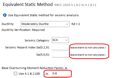
Note that when Equivalent Static Method is selected the default is for this box to be selected and for users to input the Seismic Hazard Index Values.
 Fundamental Lateral Period, Ta
The fundamental lateral period, Ta, can be calculated by the user in accordance with the building code to input into the software, or it can be calculated using Clause 4.1.8.11(3) as is the default selection within MASS.
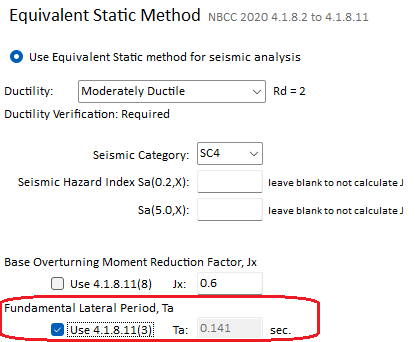 It is used by MASS to determine whether a design qualifies under the Equivalent Static Procedure as opposed to the Dynamic Procedure which is required under some circumstances. This value may be calculated outside of MASS before being input and is primarily a function of the wall height but can also be impacted by overall building dimensions and layout for some roof systems used. It is up to the professional engineering judgment of the user to make this decision.
Maximum Compressive Strain
In older versions of MASS prior to the release of MASS Version 4.0, the maximum compressive strain of masonry, εmu, was stored as a static value of 0.003. When the scope of the software was increased to include more seismic options, it became possible to design shear walls with different compressive strain values.
By default, MASS will automatically determine maximum compressive strain based on specified SFRS ductility and boundary elements designed in accordance with CSA S304-14: 16.10, 16.11.
Manual Override
In cases where the shear wall design allows for using an increased strain, it is possible to specify exactly what magnitude is used by unchecking the “Emu determined using CSA S304-14” box. When this is done, the “manually override to ” section becomes enabled where the default value can be replaced by the desired strain magnitude.
Note that while MASS will accept most numerical inputs, the value entered will still be checked to ensure CSA Standards compliance. This feature was created as a way for users to bypass the process where strain increases are handles automatically by the software.
Longest Wall in SFRS
Since MASS only looks at one wall at a time within a structure, the “longest Wall in SFRS” selection allows the user to indicate to the software whether the extent of the plastic hinge region is based upon the length of this wall or another wall elsewhere that is longer.
[pic of checkbox]
By default, this box is checked which indicates to the software to determine the height of the plastic hinge based on the length of the wall being designed. In cases where a smaller wall within the SFRS is being designed, this box should be unchecked with the length of the longer wall entered beneath.
[pic of unchecked box and wall length typed in]
Note that not all shear walls subjected to seismic loads are required to have a plastic hinge region. MASS assigns a plastic hinge as required by CSA S304-14 based on the selected ductility and aspect ratio so this input may not affect all designs. For example, changing the “Longest Wall in SFRS” selection for a conventional construction shear wall will have no impact on the design results because a plastic hinge is not required.
Differences between Assemblage Types
While the seismic tab has been implemented for use primarily in the shear wall element assemblage type, shearline and multi-storey assemblages also contain a Seismic tab which essentially sends the user input values to each element, saving the time it would take for the user to manually enter the same values into each element individually.
There are some minor differences between the way the Seismic tab will appear which depends on which type of design is being compered, explained in the subsections below.
Shear Wall element
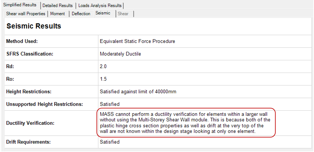
Unable to Perform Ductility Verification
For shear wall elements where the total height exceeds the assemblage height, a message appears in the seismic tab alerting the user that the verification cannot be performed using MASS.
A message appears within the Simplified Seismic Results as well
Excluding from Plastic Hinge
The shear wall element assemblage offers an additional option labelled “This element is not within the plastic hinge” that cannot be seen anywhere else in MASS. It is not selected by default and can be selected by the user in the input area pictured below.
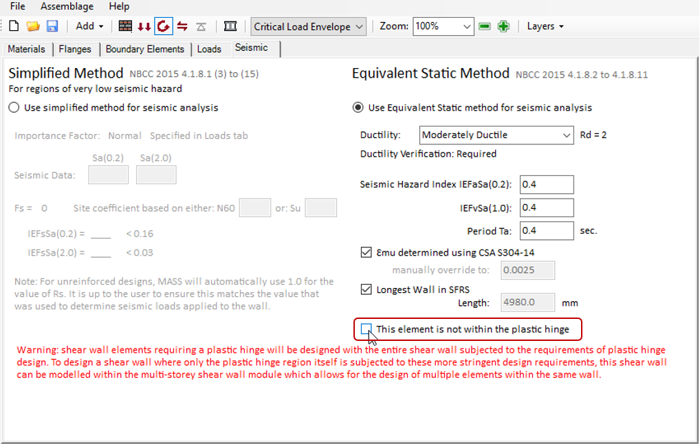
By default, with the box left unchecked, MASS will design the element against the additional plastic hinge region requirements. If the element being designed is further up the height of the wall and outside of the plastic hinge region, this option can be selected which will inform MASS to not apply any of the additional design restrictions.
Note: This selection was added for cases where a designer may wish to copy a storey design from a multi-storey shear wall but not have to deal with the ductility verification since MASS used to default to treating the shear wall element as if it were at the bottom of the total height shear wall it is part of.
Additional messages
MASS will also display a contextual message within the seismic tab for shear wall elements within a wall requiring a plastic hinge region.
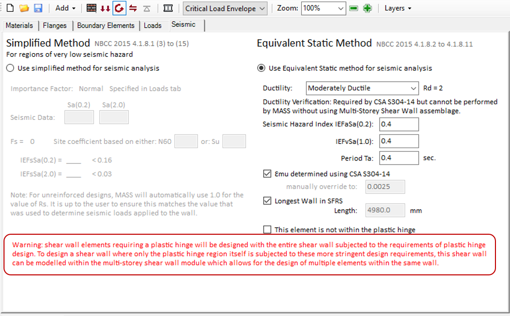
Since shear wall elements contain one design and cross section for the full height of the element, MASS will apply plastic hinge requirements to the full wall and not just the required region.
For more information about these designs and how to break up the design of one wall into two sections, click here for more information.
Multi-Storey Shear Wall
Structural Irregularities
There is an additional option within the Seismic tab before designing a Multi-Storey Shear Wall that reads: “Design shear walls against Type 1,4 and 6 Structural Irregularities”
[fig of option]
This selection is enabled by default and will ensure that the final design will not have large reductions in stiffness or strength, as prescribed in the National Building Code of Canada. If this option is disabled, MASS will not continue designing and calculate deflection, regardless of whether the design is regular or not.
For more information about the Multi-storey shear wall design process and structural irregularities, click here.
Shearline
Any designs requiring the use of a plastic hinge region (and ductility verification calculation that goes along with it) are not permitted within the shearline module. As a result, the only options are shown below:
[pic of ductility drop-down for shearline]
For more information regarding this decision of excluding designs involving a ductility verification, please contact the MASS software authorized technical service provider, CMDC.