

Latest Software Blog Posts
Protip: Use the Multi-Storey Shear Wall Module to Design… Single Storey Shear Walls?
Yes, you did read that right! The Multi-Storey module can be used to break a single storey design into multiple shear wall elements.
With the release of MASS Version 4.0, a new module was announced that specifically deals with the design of shear walls where loads can be applied at various floor height locations.
There exists design scenarios in which it can be beneficial to utilize different patterns for grouting and reinforcing along the height of a single storey shear wall. The most typical scenario where this would be utilized is for tall walls that are governed by the ductility requirements within the plastic hinge that come along with Post-Disaster importance categories. For example, a water treatment facility with relatively nominal loading.
The shear wall element module in MASS uses a single cross section for the design of the entire height of the wall. With the addition of the new Multi-storey module in MASS Version 4.0, users can design a shear wall that is broken down into individual elements, MASS can use one design at the lower portion of the wall and apply a separate design for the remaining wall.
Note: Any change in vertical reinforcing and grouting patterns will have a significant effect on the out-of-plane design which is typically one of the main constraints in tall, vertically spanning walls. The multi-storey module only designs for in-plane requirements and out-of-plane behaviour should always be checked separately.
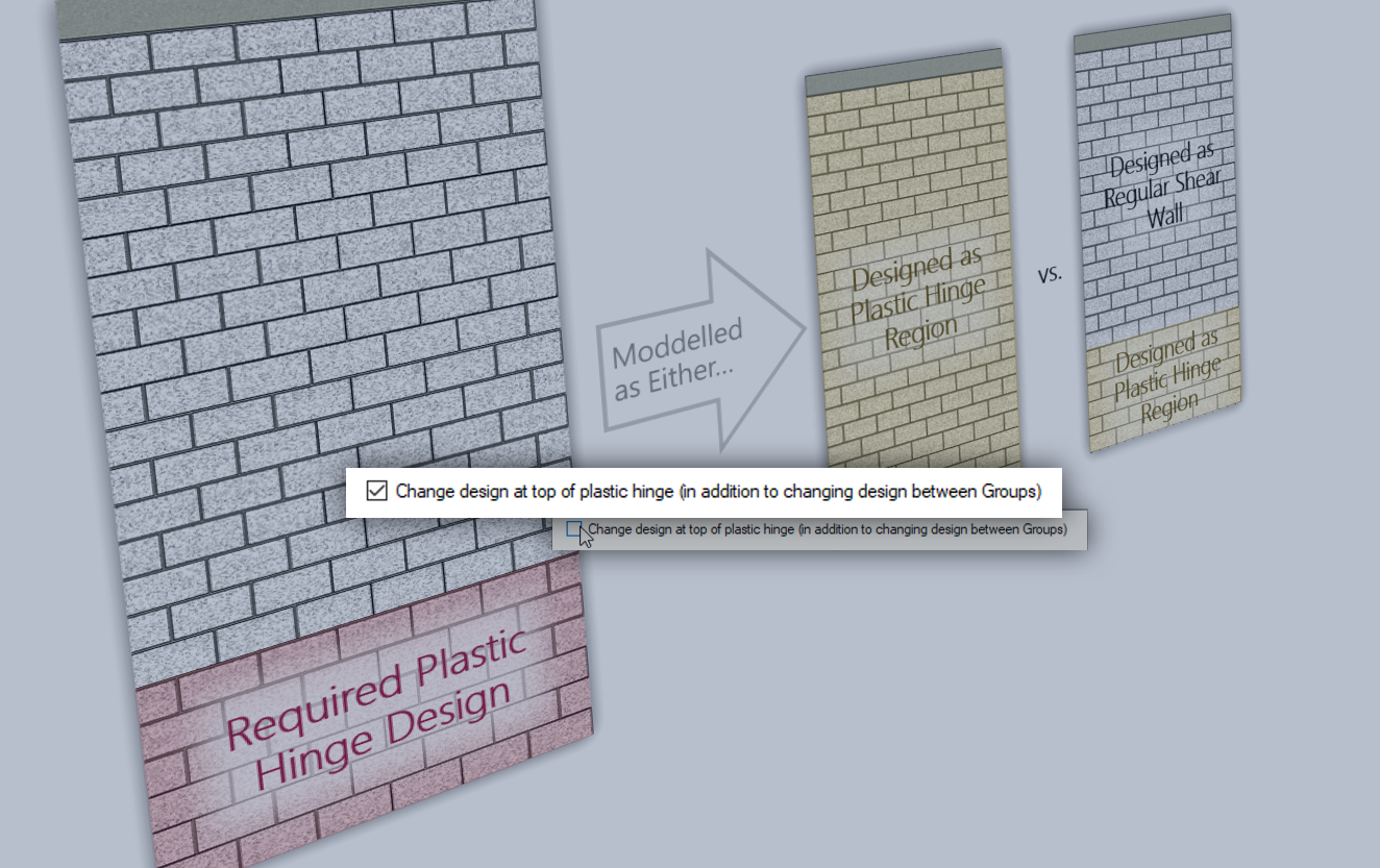
Useful for changing the design around the Plastic Hinge Region
Shear walls with an aspect ratio larger than 1 (taller than they are long) which are also designed as Moderately Ductile (Rd = 2.0) or Ductile (Rd = 3.0) require a plastic hinge. These designs require a plastic hinge region with additional design and detailing requirements. More can be read about this in the Seismic Tab section linked here.
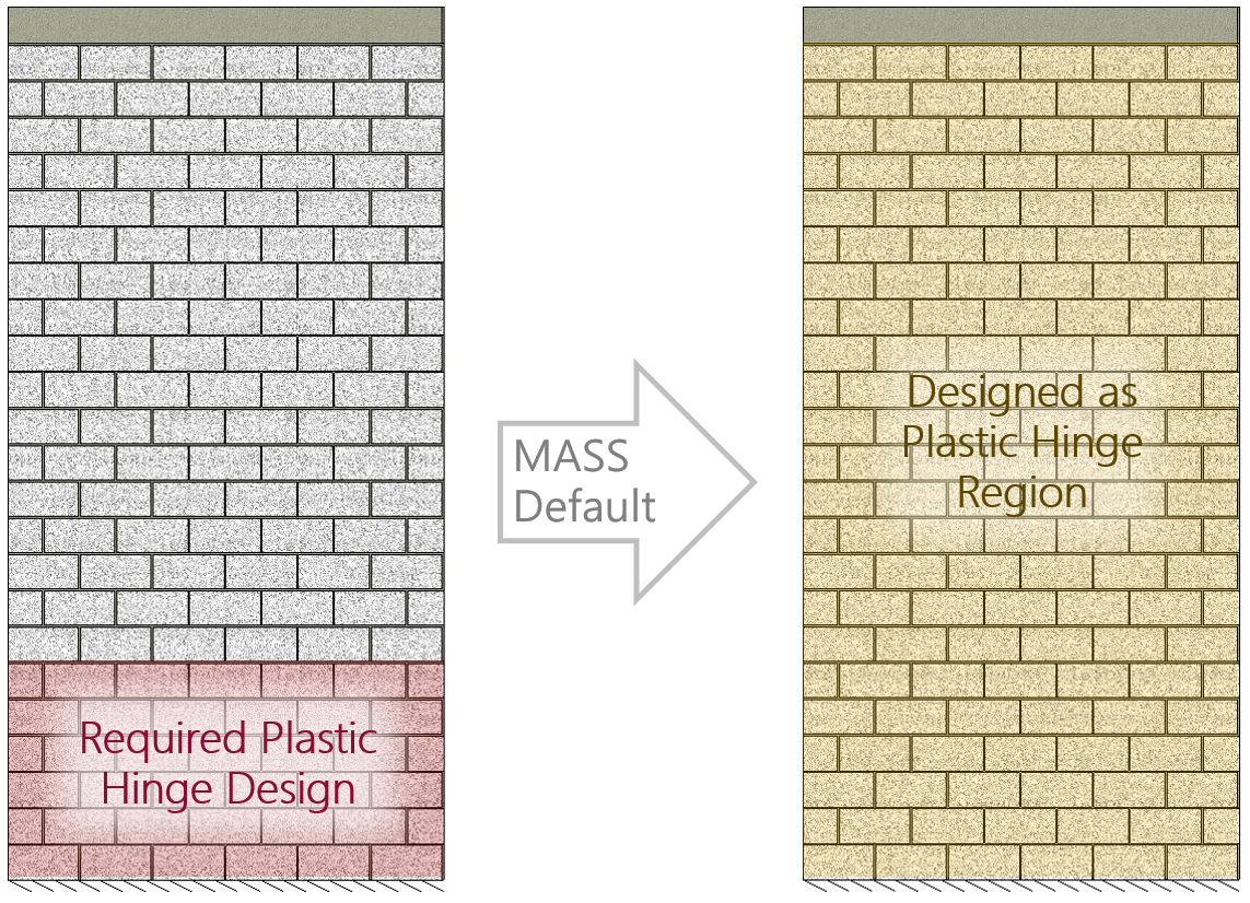
By default, MASS will design any element that is even partially within the plastic hinge region using the plastic hinge requirements for the entire height of the wall.
This can be changed by splitting the storey design into two elements: one that is completely inside the plastic hinge, and one that it completely outside that same region. The default MASS setting to treat the whole storey as if it were part of the plastic hinge can be disabled, resulting the following behaviour:
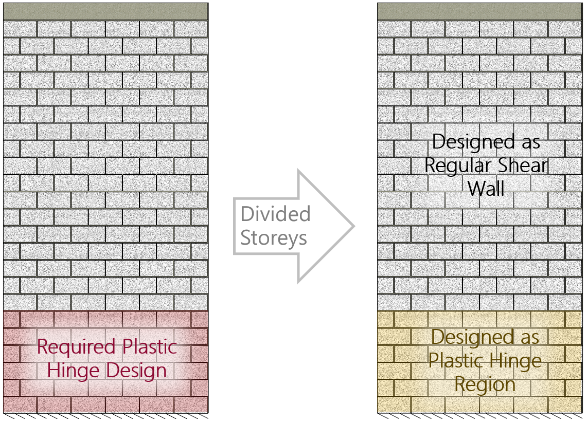
When a storey is divided around the plastic hinge boundary, there are two Storey 1 designs performed. This is further explained with the software steps and more specific details later in this post (click here to jump ahead).
Note: Designs where the required plastic hinge height occupies a large portion of the shear wall, it may be better to simply design the entire wall as one element meeting plastic hinge requirements for the sake of simplicity. This is at the professional discretion of the designer.
Why splitting storeys might be beneficial
Whether or not a shear wall element must be designed against plastic hinge criteria can have a large impact on the final design. Fully grouting the wall and extensive use of bond beams can create a wall that is very much over-strength without considering the additional requirements of the plastic hinge. Additionally, this can also cause the cells to be overly congested with reinforcing; especially in areas with reinforcement lap splices.
Being able to switch from fully grouted to partially grouted, increasing the spacing of bond beams (or even switching to joint reinforcing entirely), can reduce the material costs, labour costs, as well as cell congestion.
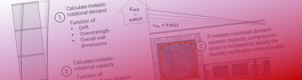
In cases where the ductility verification becomes an issue in achieving a successful, passing design, a higher strength masonry unit or other cross sectional changes may be required in order to keep the compression zone within a smaller region of the wall upon failure. This is a more complex relationship and the impact on the final design is more a function of the specific building geometry and loading.
All of these are changes that may not be desired for the entire height of the wall which is why there is an option to separate the storey design into two elements.
How to design a Single Storey with Two Elements
Using the Multi-Storey Shear Wall module, a design can be broken into multiple elements within one storey, a setting can be enabled in the Assign Groups Tab that is unchecked by default. At the bottom of the input window when the Assign Groups tab as been selected, there is a checkbox labelled “Change Design at top of plastic Hinge (in addition to changing design between Groups)“, shown below:
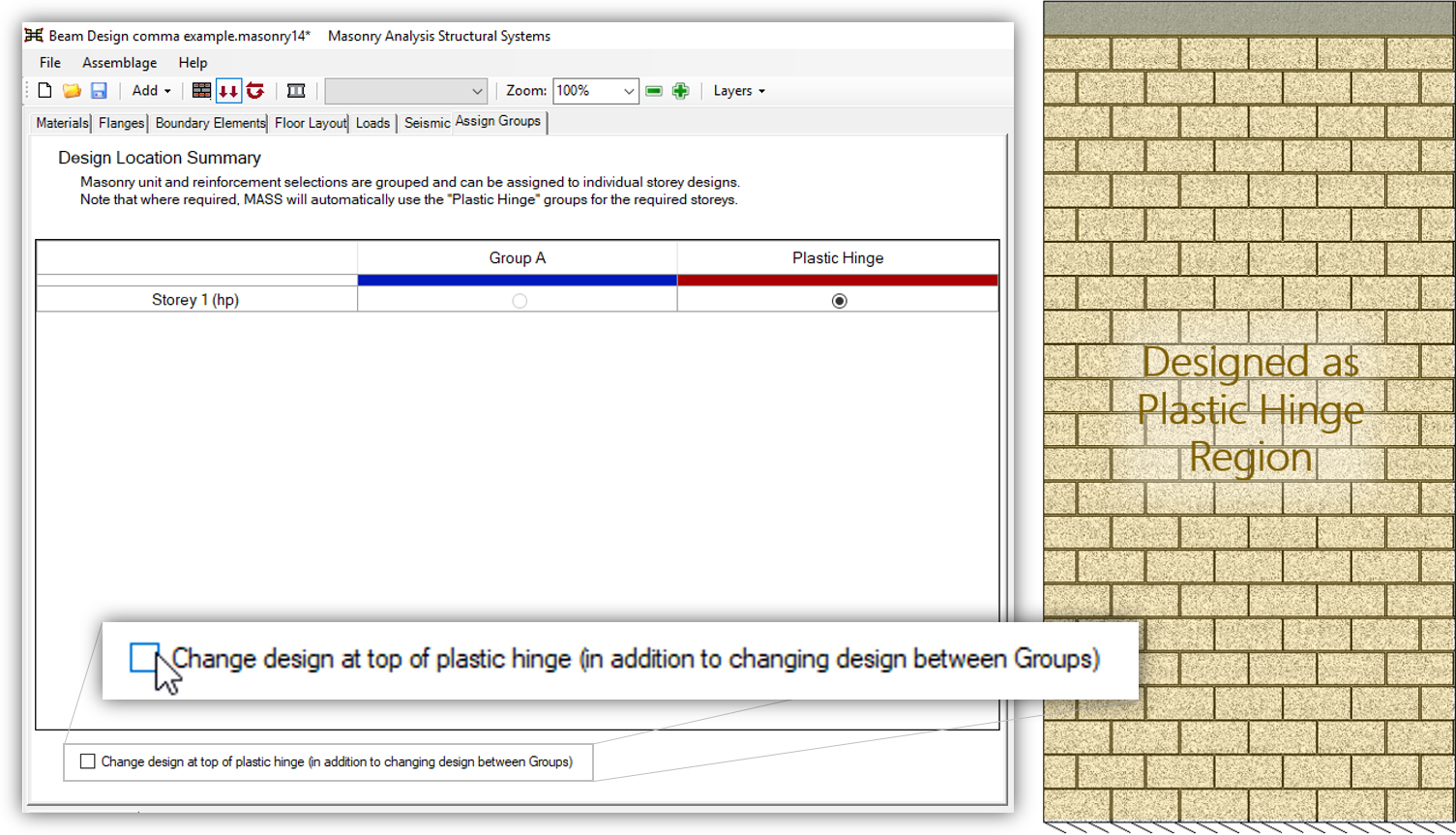
The default software behaviour is for the entire storey to be designed as meeting the plastic hinge requirements as seen in the Assign Groups tab in the Multi-Storey Shear Wall module. When the option is selected, the result is an added shear wall element.
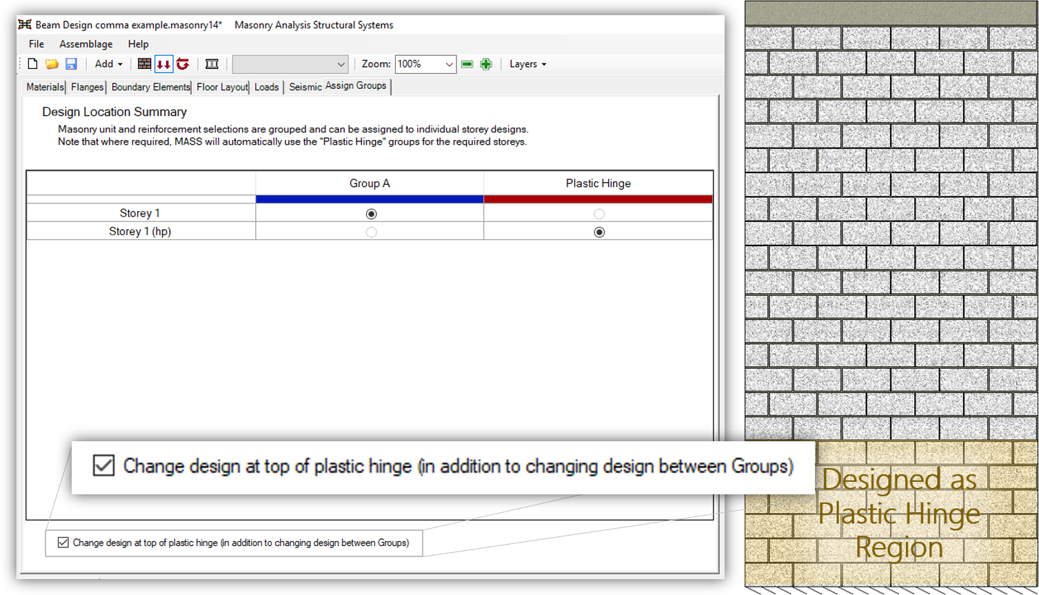
They would appear as individual shear wall element designs within the multi-storey module, listed as:
- Storey 1
- This is the shear wall element design that does not have to be designed to meet plastic hinge requirements. It is designed using one of the user created and modified Groups.
- Storey 1 (hp)
- This is the shear wall element design that does have to be designed to meet plastic hinge requirements. It is designed using the dedicated Plastic Hinge group which can be modified but not copied or deleted.
As mentioned previously, whether or not to break apart a storey into multiple sections is at the professional discretion of the designer. The added complexity and drawing preparations/review may not be worth the savings in material costs but for large single storey shear walls, this might be an option worth consideration.
Can I choose another location where the storey is divided?
No. MASS gives the option to divide a storey into sections that are on either side of the top of the plastic hinge region. That being said, the plastic hinge is a function of the longest wall in the seismic force resisting system (SFRS). If there is a longer wall elsewhere within the SFRS, it increases the height of the plastic hinge of the shear wall being designed.
If a story is divided into multiple sections for reasons other than the modelling of a plastic hinge, this can be done through the use of manual load distribution to shear wall elements that are created independently of a multi-storey assemblage. This process is covered in an article on the CMDC website, available here. While it is faster to use multi-storey to model a shear wall with multiple elements, this would fall under a category of design that is outside of the intended scope of the multi-storey module in MASS.
Any Questions?
As is the case for any MASS related inquiry, we try to encourage everyone to simply pick up the phone and give MASS support a call if you encounter any issues at all. 30 minutes of scratching your head may be solved by a 5 minute conversation with support staff.
MASS support is provided through the authorized technical support provider of NMDP, the Canada masonry Design Centre.
Wow that was incredible. Thanks so much for sharing! If anyone sees this, please make my day by posting a comment below sharing a time when you were able to use MASS to help a close friend or family member in need.
This article LITERALLY saved my marriage. Brad is a word wizard, Oprah book club worthy!