

Latest Software Blog Posts
Slab Assumptions in Multi-Storey Shear Wall Design
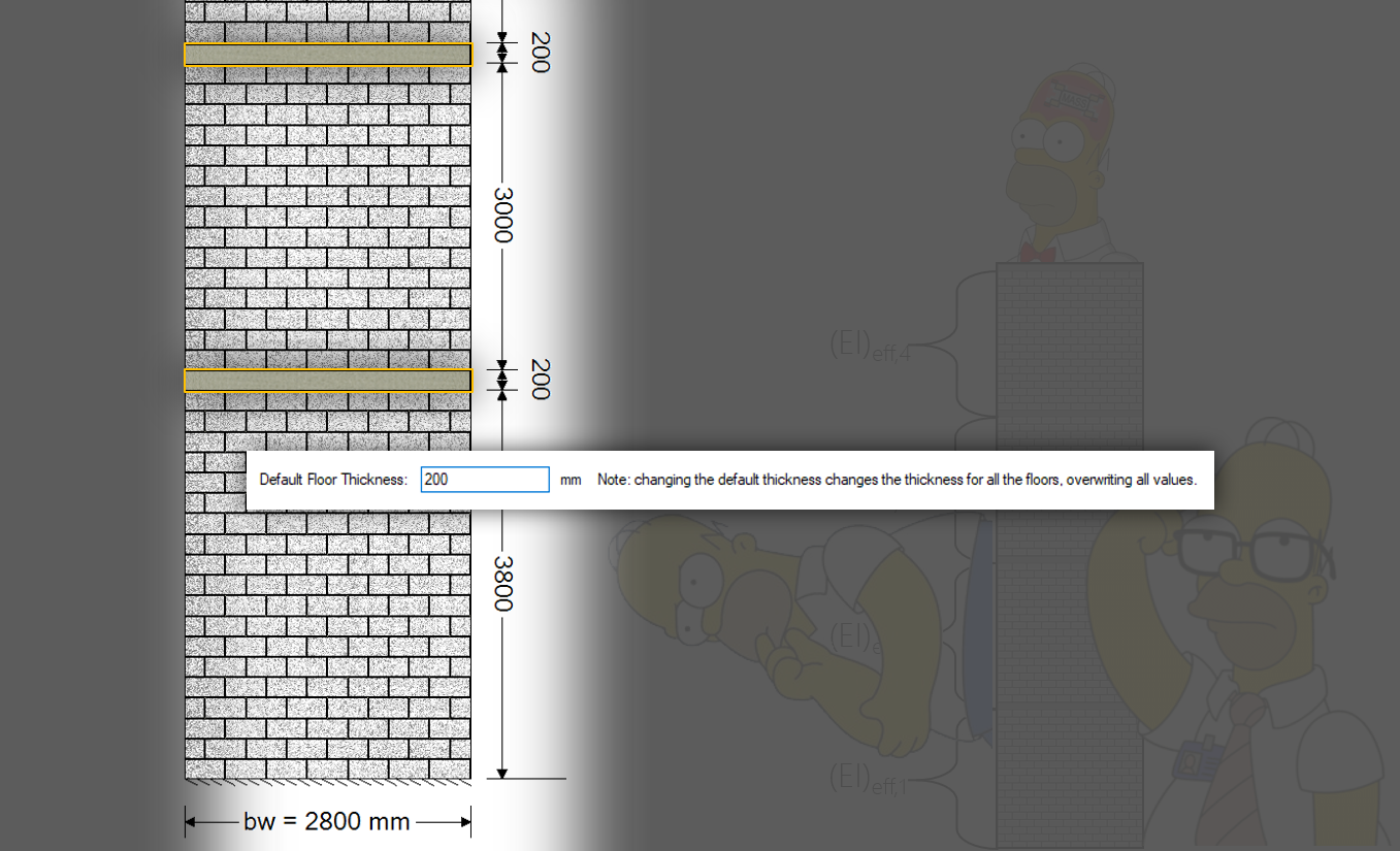
MASS does not design floor slab systems but allows for them to be modeled within Multi-Storey Shear Walls for the software to design the masonry supporting and spanning between them.
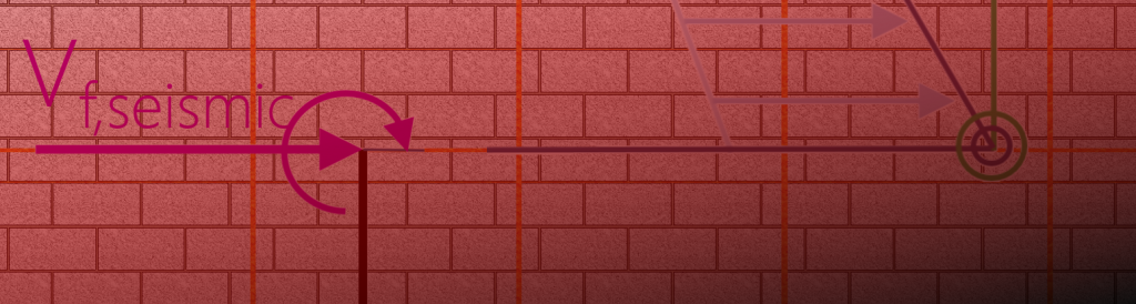
Slabs are basically rectangles on the cross section that appear between designed shear wall elements. It is assumed that they are capable of transferring lateral loads from storeys above into the corresponding elements below without slipping or sliding.
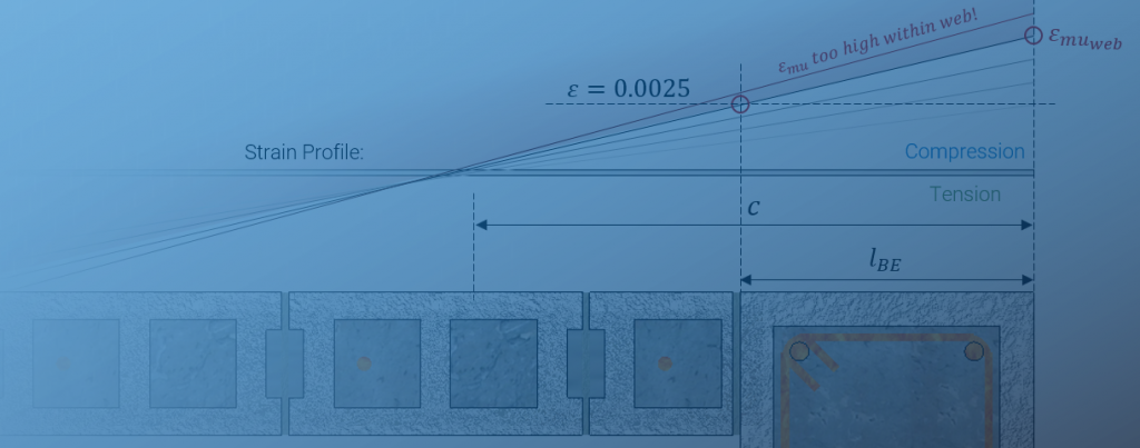
It is assumed that the slabs are capable of resisting the compressive forces on the compression sides of the shear wall elements above and below.
No rebar is shown within the slab area when in practice, vertical bars are likely continuous between floors. It is assumed that vertical bars placed within the masonry shear wall cross section are developed at the top and bottom faces of the wall element to yield in tension, without specifying details to achieve this connection.
As covered in a separate post regarding inter-storey drift calculations, it is assumed that the effective bending stiffness of each slab is the same as the shear wall above to simplify the calculation and be conservative. Additionally, there is no torsional restraint provided by connected slabs to multi-storey shear walls.
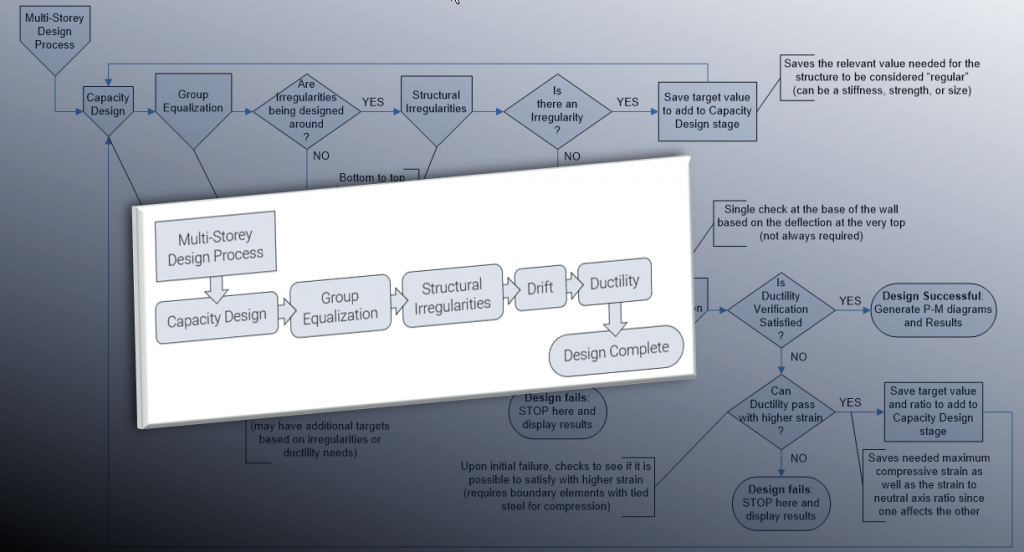
For more information on multi-storey shear wall design, click here to visit the main multi-storey help page with links to the various topics and subsections within.
For more great slab info, feel free to contact the experts directly: https://www.marbleslab.ca/