

Effect of floor slab stiffness on multi-storey shear wall deflection
Comparing the assumptions used by MASS to a rigid slab assumption (with example)
Contents
This page outlines the effect of the floor slab and effective bending stiffness properties used for those locations within the wall when calculating shear wall drift. An example is used at the end where the results are compared to the same wall designed using MASS.The table of contents (left) can be expanded and used to jump ahead to the relevant sections of interest.
Slab stiffness as modeled by MASS
When determining the drifts that a building will undergo, the behaviour of the concrete slab has a minimal effect due to the relative height between the slabs and the shear wall itself. For the example considered within these help documents, the thickness of the slab represents less than 10% of the elevation height – or 200mm out of 3000mm shear wall height for each storey.
MASS takes a conservative approach when determining the bending behaviour of the portion of multi-storey shear wall assemblage occupied by floor slabs:
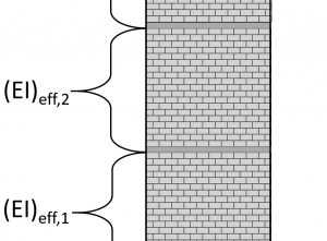
MASS assumes that the effective stiffness, (EI)eff, of the slab is equal to the effective stiffness of the wall resting above. This is done both for ease of calculation, and also as a conservative assumption which yields higher lateral drifts used for the ductility verification (when applicable) as well as multi-storey drift limits checks.
Determining the conservative approach
If the effective bending stiffness for the floor slab is likely greater than that of the masonry shear wall above and beneath, the effect of taking that higher bending stiffness into account would result in lower calculated shear wall drift. Since shear wall deflection is required for inter-storey drift limit checks as well as for the ductility verification (when applicable), using the approach yielding larger deflections was determined to be the conservative method in the absence of more direct, detailed guidance from Canadian codes and standards.
The effective bending stiffness is the product of the modulus of elasticity (Young’s Modulus) and the moment of inertia and broken down further below.
Modulus of Elasticity
The modulus of elasticity (Young’s modulus) for concrete is typically greater than that of concrete masonry assemblages. This difference may contribute to a possible difference when comparing the effective bending stiffness.
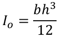
Moment of Inertia
The Moment of Inertia for a slab will be greater than for the wall, even when considering the subtraction of vertical steel. This is due to a much larger ‘b’ term in the Moment of Inertia equation.
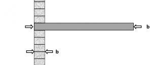
The exact value of ‘b’ would need to reasonably be determined for the slab based on how much of the slab is effective in resisting the moments applied through the shear wall along the in-plane direction. Moving further away from the shear wall location, it becomes less and less reasonable to assume that the portion of floor slab is effective in resisting the in-plane bending forces and providing additional effective bending stiffness.
Combining the individual contributions from the increased modulus of elasticity and effective bending stiffness of the floor system, it is difficult to conclude on a precise effective bending stiffness value used by MASS. That being said, the assumption where the same stiffness as the wall above is meant to be reasonable but conservative.
Drift sensitivity to slab bending stiffness
To what degree are drift result impacted by the stiffness where floor slabs are located?
Since there is no direction from codes and standards in determining the effective stiffness in the in-plane direction of floor slabs within masonry walls, the most extreme case can be tested to illustrate exactly how sensitive the shear wall deflection is to slab stiffness.
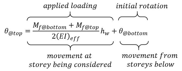
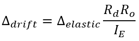
For the four storey example shear wall, assuming the slabs are infinitely stiff (a rigid body within a deflecting wall) can be examined. A rigid slab will not bend and therefore will not deflect due to applied moments. Looking at the equation for calculating deflection, this in effect simply removes the first term from within the deflection formula.
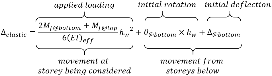
The same is true for rotation, where the first term will be zero from no increased movement within the height of the slab treated as a rigid body.
The true behaviour of the slabs will be somewhere between the conservative assumption discussed here and used by MASS, and the assumption that the slabs are rigid. To compare the effect of rigid slabs,the example from the Multi-storey deflection page and solve for the deflections along the four storey structure whilst assuming rigid slabs.
Rigid slab example
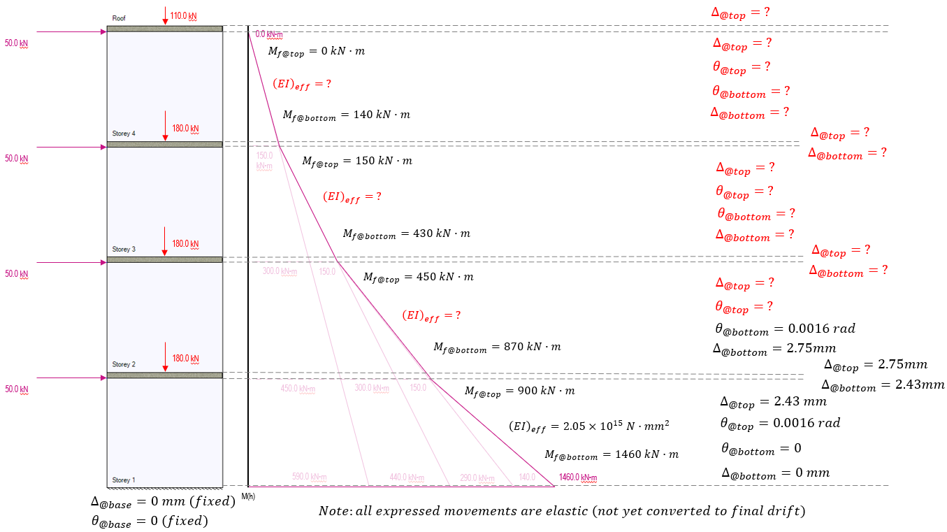
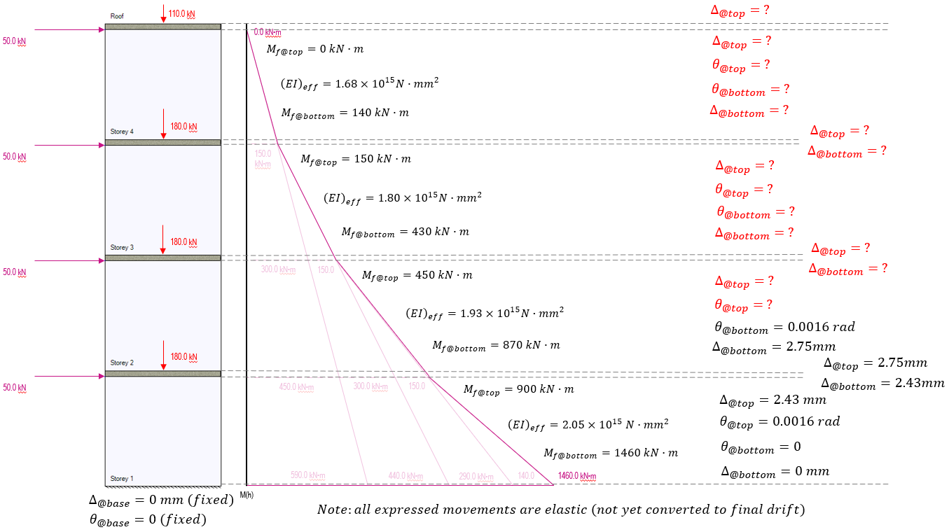
This example determines the total drift at the top of the shear wall shown below (as well as the drift at each floor in between) assuming rigid slabs.
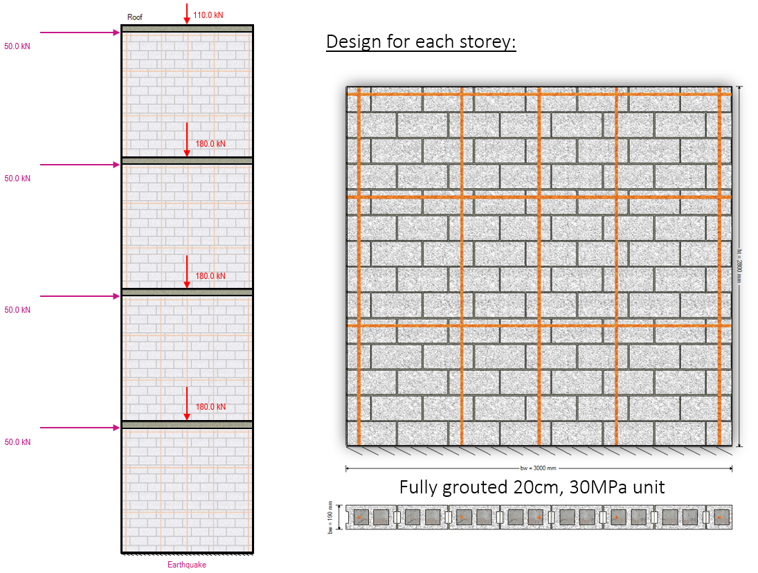
Axial loads are specified at the top of each floor and include self-weight applied from any masonry above.
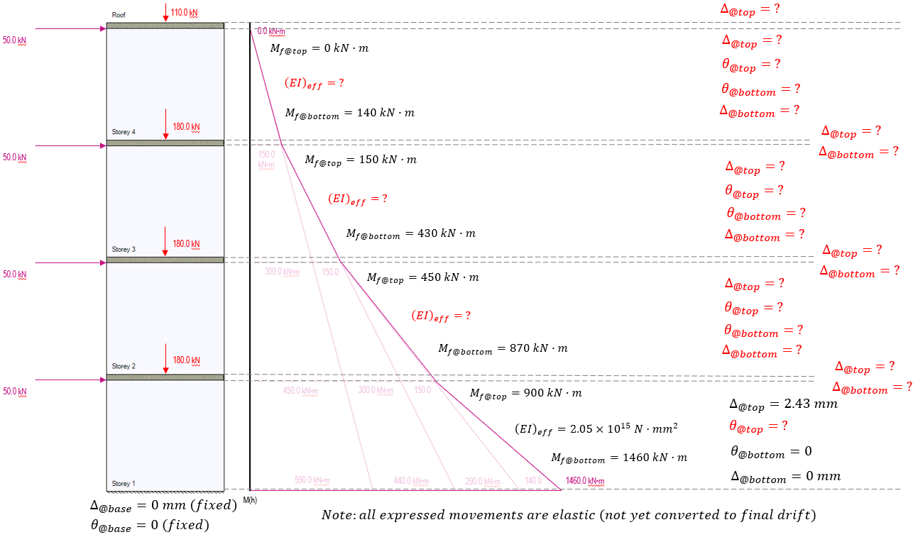
The cross sectional properties, as well as drift for the top of storey 1 have already been calculated in the shear wall element deflection article. The results from that example are summarized below and this page continues from that example left off.
Storey 1 Movement
Since we are assuming the slabs are rigid, we no longer have to calculate deflection for 4 storeys and a roof slab. We now need to calculate deflections for 4 storeys and 4 slabs.
Before any deflections can be calculated further up the shear wall, the rotation must be calculated at the top of storey 1.
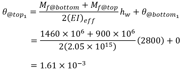
Recall that this is expressed in radians which happen to be unitless since it is measured as one part arc length per radius length where the distances cancel each other out. This rotation is then carried to the base of the area used to calculate the rotation and deflection of storey 2.
Now to determine the deflection along the height of the slab. The only deflection that is occurring within the slab is from the rotation.
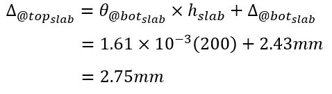
The rigid slab will not bend, so the rotation at the top of the slab will equal the rotation at the bottom of the slab.
Now we proceed to the shear wall on storey 2.
Storey 2 Movement
Before proceeding with those calculations, the effective stiffness must be adjusted. Although the cross section is exactly the same and will have an identical cracked and uncracked moment of inertia, the stiffening effects will differ as they are a direct function of the axial load acting at those locations.
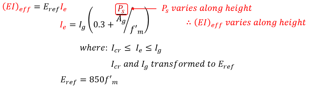
Technically, even between floor levels, the effective bending stiffness will change slightly depending on the amount of self-weight acting on that location between floors. MASS takes all self-weight and applies it at the floor location so that one stiffness value can be used between the top of each shear wall element.
These effective bending stiffness values are calculated below for the remaining three shear wall sections as a function of the axial load for the seismic load case considered:
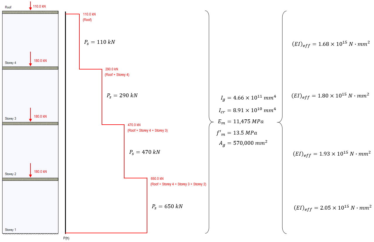
These effective bending stiffness values can be used to work up the shear wall, starting from the second storey where the elastic rotation and deflection have already been determined, as shown below:
Using the Storey 2 effective bending stiffness as well as the deflection from the top of the slab (2.75 mm) and rotation (1.61×10⁻³ rad), the deflection and rotation can then be calculated for the top of storey 2:
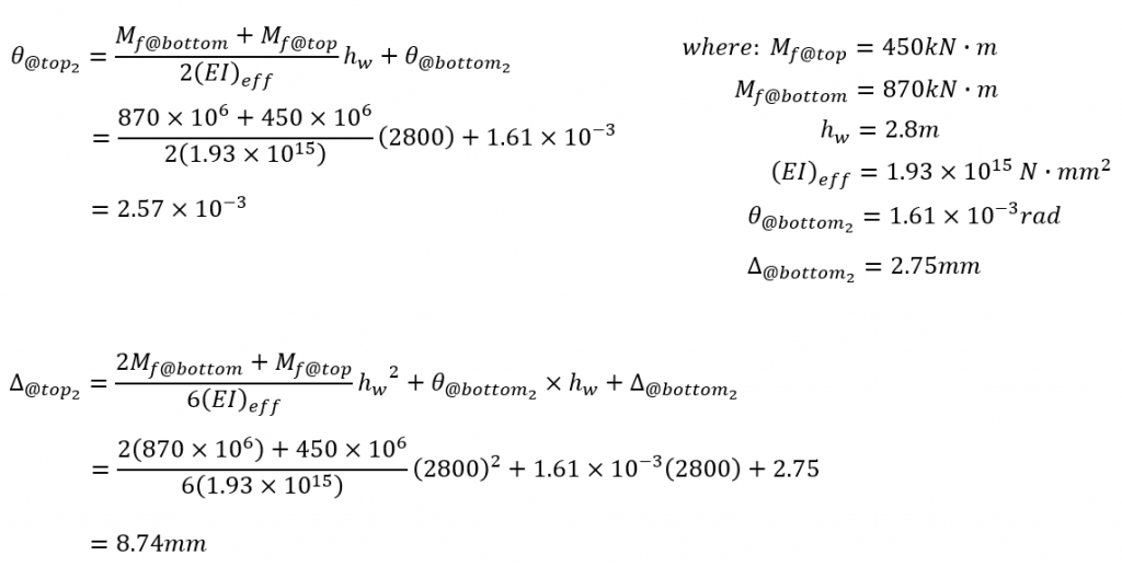
The end result at the top of storey 2 is an additional rotation of 0.96×10⁻³ radians and additional deflection of 5.99mm (1.48mm due to applied loading and the remaining 4.51mm resulting from the initial rotation at the base of storey 2). Adding this rotation and deflection at the top of storey 2 and updating the multi-storey diagram, values and remaining unknowns are shown below:
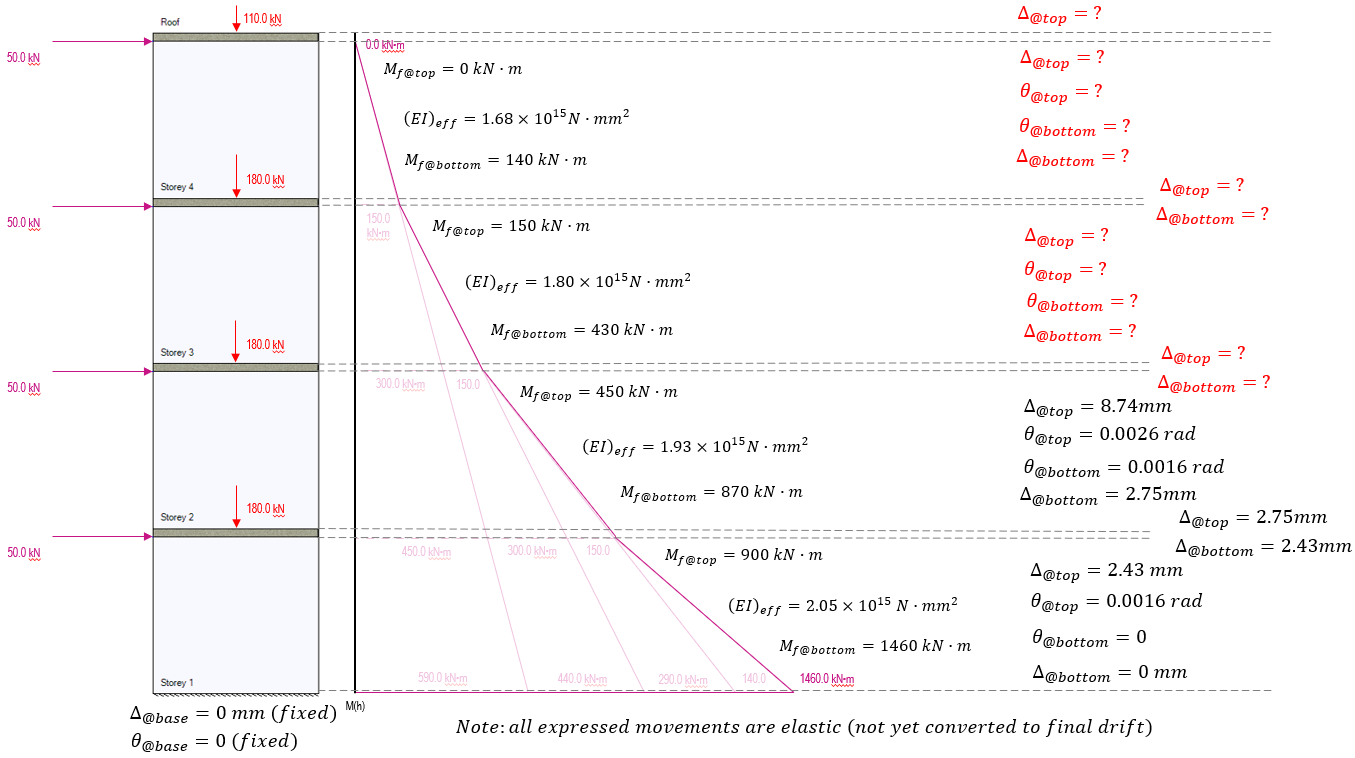
Full height Movement Profile
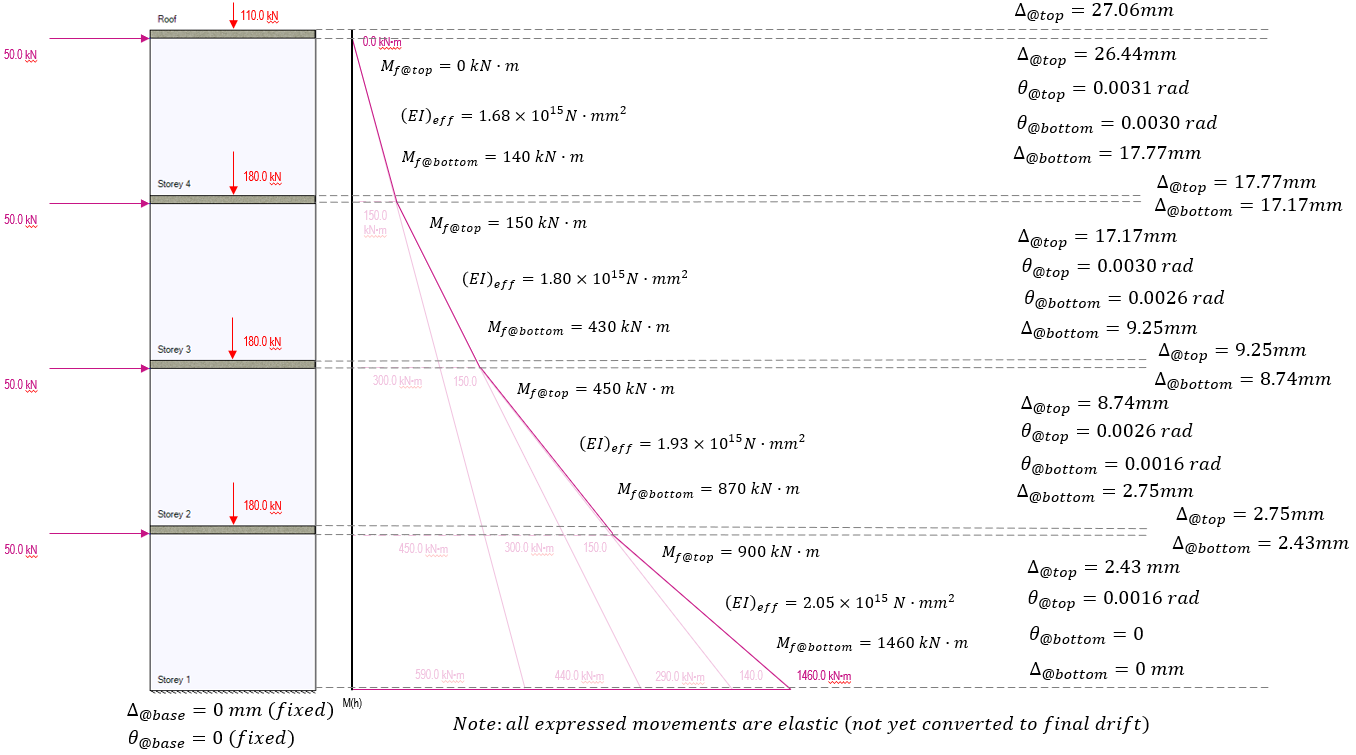
This process is repeated with the deflection resulting from rotation being calculated for each floor slab. This being followed by deflection and rotation calculations for the shear walls along the height of the elevation with the final values shown below:
Comparison and Concluding Thoughts
For determining the actual drift values from the elastic deformations above, the value would need to be multiplied by the ductility and over strength factors divided by the importance factor:
However for the purposes of this example, we are simply comparing the assumptions used in MASS against the assumption of the slab being a rigid body. In the table below are the elastic deflection values along the elevation for both methods. The column on the right highlights the percent difference between the two methods.
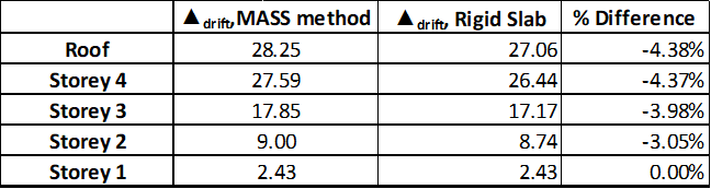
At the top of the elevation we see a 4.38% percent difference between the methods. As stated earlier, the true behaviour of the slabs will not actually be “infinitely stiff”, so it safe to say that the assumptions made in MASS would have a percent error of LESS than 4.38% and be on the conservative side for the above layout and loading.
An interesting trend observed in the table above is that the influence of a rigid slab is much greater near the base of the elevation. This is due to the greater moments at the base, and the fact that we are not considering any bending in the slab due to its rigidity. There is a full 3% different linked to the rigidity at the first floor slab, whereas the differences are 0.93% and 0.39% for the second and third floor slabs respectively.
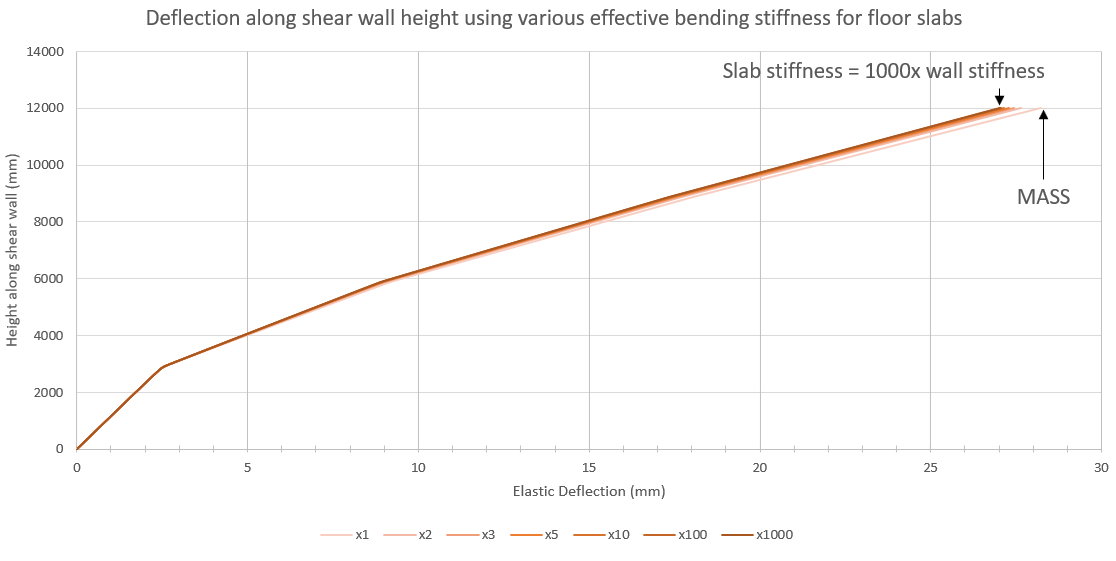
The figure below shows the deflection profile with various stiffness ratios applied only at the floor slab locations. The lightest curve plotted represents the deflection where the floor slab stiffness matches that of the wall above (MASS software assumption) with the profiles for each substituted stiffness plotted using progressively darker shades.
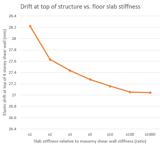
Zooming in to only the top deflection values, it can be observed that there are diminishing returns as floor slab bending stiffness increases. The jump from one to two times the effective stiffness results in a similar jump in going from two to one thousand times.
Continue Reading:
This page was linked from within the Multi-storey shear wall deflection page. Effective bending stiffness is also discussed within the Shear wall element deflection page.
Was this post helpful?