Latest Software Blog Posts
Bug Notification: Drift Values instead of Elastic Deflections used for Inelastic Rotational Demand
The current MASS approach in Version 4.0 means that linear elastic deflections are over-corrected in a way that largely overestimates demand, making ductility verifications far more difficult.
Many shear wall designs require that a ductility verification be performed and satisfied. While the software has a number of systems in place to attempt to arrive at a successful design, there are still cases where it can be difficult to satisfy the various seismic requirements. The issue described in this article pertains to the ductility verification and can make it excessively difficult to satisfy a ductility verification as inelastic rotational demand is currently calculated to be much higher than required within MASS.
Disclaimer: This post is exclusively intended to provide insight into the approach taken by the MASS design software in interpreting a CSA S304-14 code compliant seismic design. It is up to the professional discretion of the designer to input an appropriate layout, boundary and loading conditions, interpret the results, and determine how they should be incorporated into their designs. As per the end user license agreement (and also recommended within PEO’s guidelines for using engineering software), a tool cannot be considered competent and reliance on a tool does not relieve the user of responsibility.
A quick summary of the issue is shown below with additional background information and further reading in subsequent sections. If you have any questions regarding this bug, please do not hesitate to contact MASS technical support.
Summary
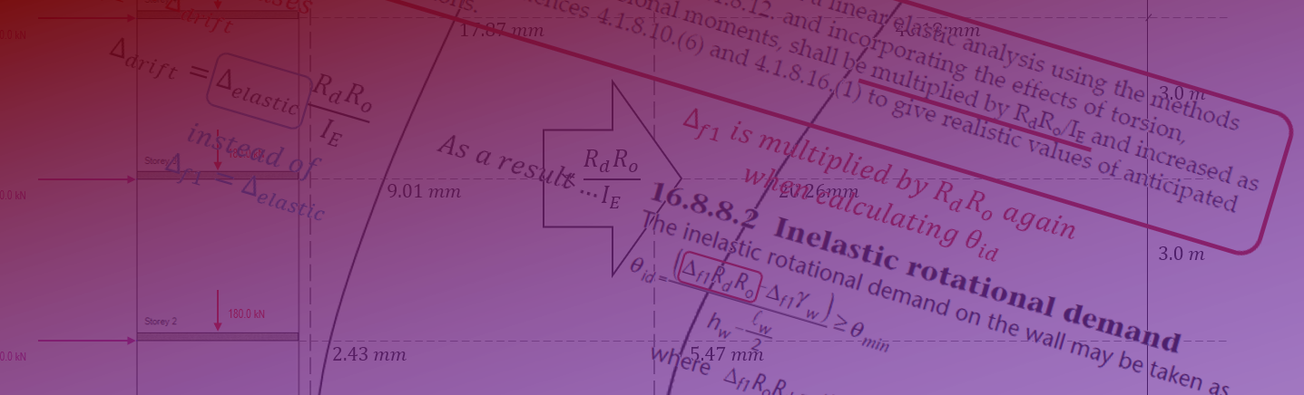
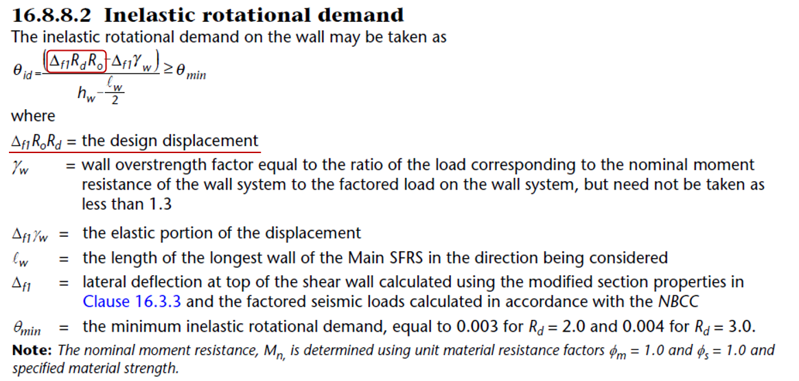
When performing a ductility verification, MASS currently uses drift values instead of elastic deflections in determining θid, inelastic rotational demand.
Since the expression for θid also scales up the movement similarly to the National Build Code of Canada, ductility verifications are excessively difficult to satisfy as demand before considering overstrength is higher than expected by factor of RdRo.
For normal importance category, conventional construction structures, this represents a 125% increase, resulting in excessively conservative ductility verifications.
Background Information
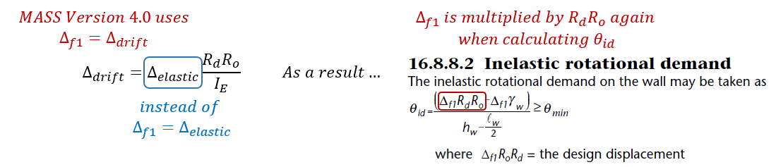
The deflection used to perform a ductility verification is referenced in the variable Δf1, representing the deflection at the top of the wall. The issue causing this bug is that the wrong movement is referenced for Δf1 as the expression where it is used also has a similar modification to deflection included to consider actual expected movement.
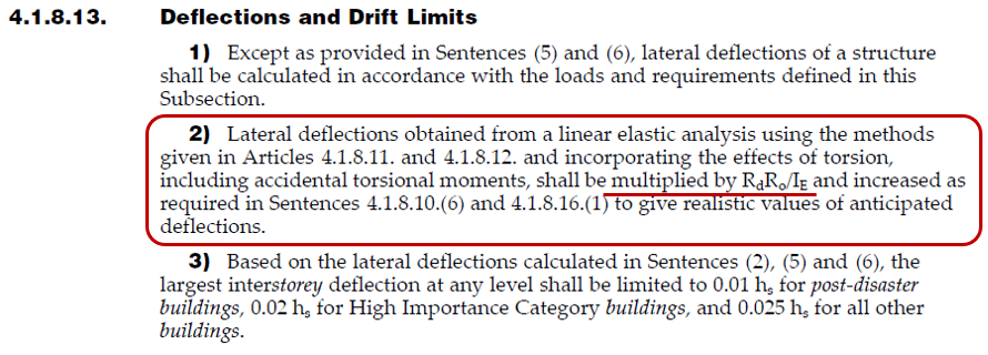
For the purpose of checking drift, the actual expected movement of the shear wall is determined by scaling up the modelled linear elastic deflection in accordance with NBCC 2015: 4.1.8.13 (2):
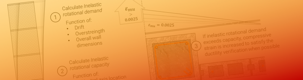
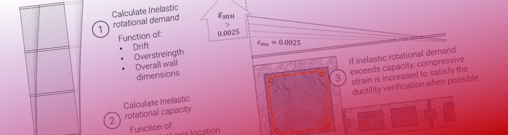
Drift is determined within MASS be scaling up the elastic deflection at the top of the wall. This is done by first determining the shear wall movement based on linear elastic behaviour and effective cross sectional properties which account for cracking as well as stiffening from increasing axial loading. The calculation process is summarized below:
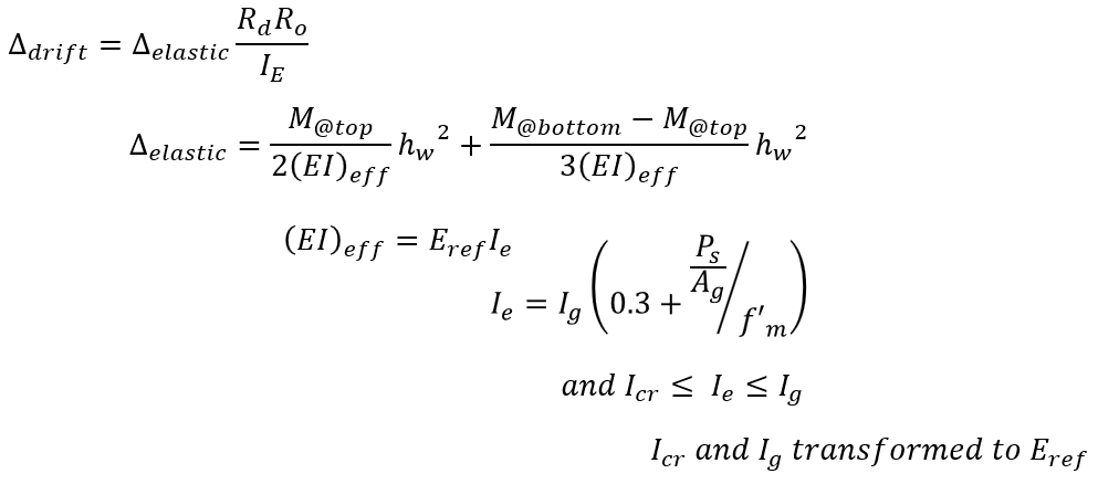
The above figure was taken from a series of articles explaining drift calculations, available here.
By using drift instead of elastic movement for Δf1, a portion of demand is scaled up a second time by factor of RdRo within the inelastic rotational demand expression. This is after it was first scaled up when converting from elastic movement to a drift value which should not be done when performing a ductility verification.
MASS currently uses drifts but should use linear elastic deflections, since that movement is scaled up to being a drift within the θid term where it is immediately multiplied by RdRo essentially accounting for the same thing.
Until it is changed, linear elastic deflections are effectively multiplied by RdRo twice by the time they are factored into the inelastic rotational demand, making ductility verifications difficult to satisfy within MASS and excessively conservative.
The following example illustrates this difference and its impact on satisfying a ductility verification.
Example
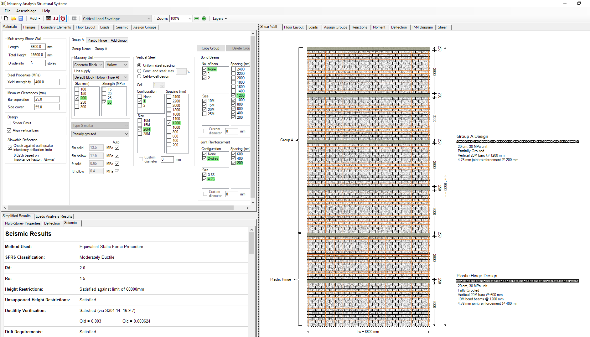
Consider the following shear wall, designed using a 20cm, 30 MPa unit with vertical 20M bars placed at a spacing of 600 mm in the plastic hinge elements and 1200 mm for the rest of the storeys. The importance category is Normal.
The wall is then loaded as shown below:
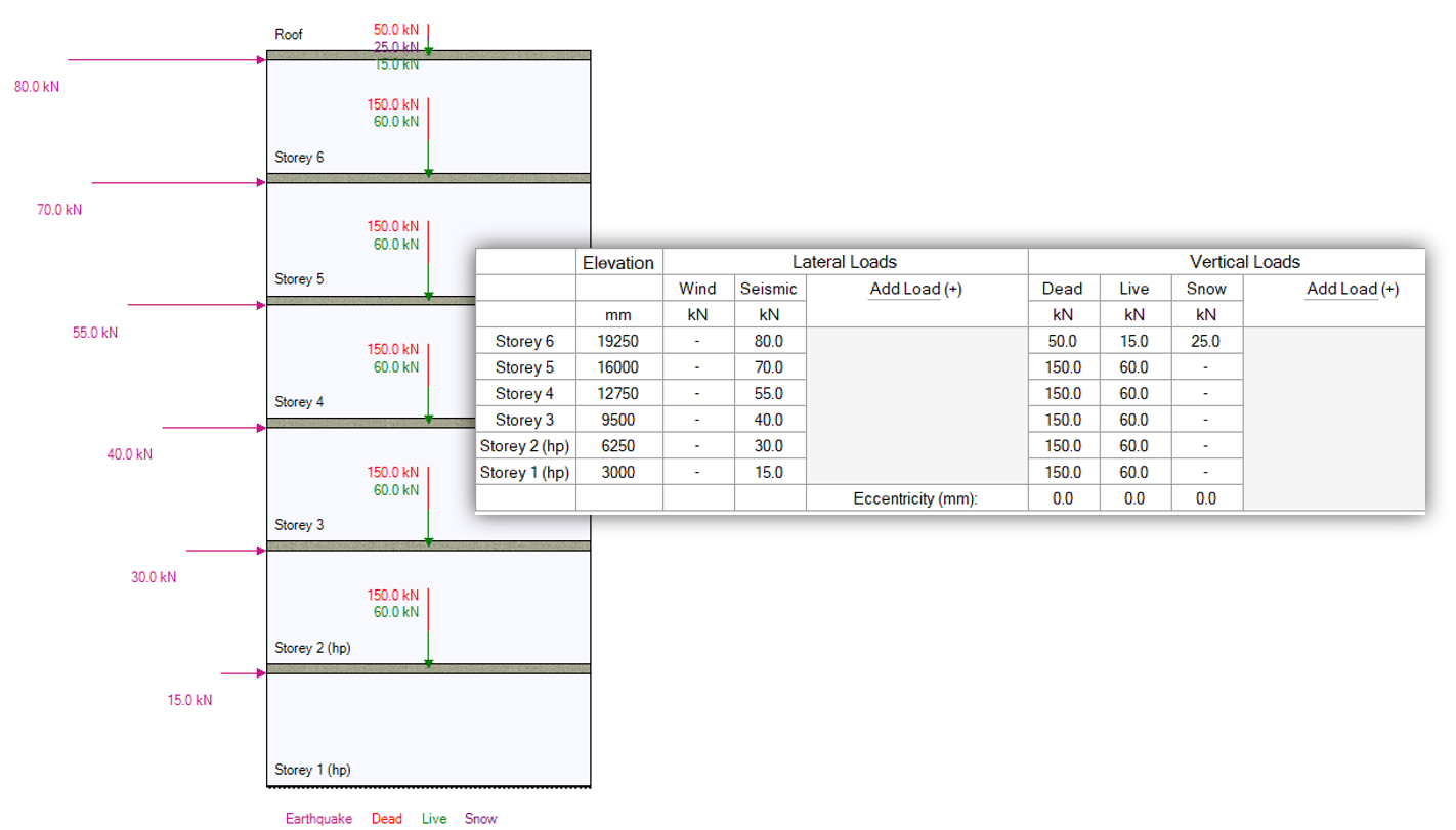
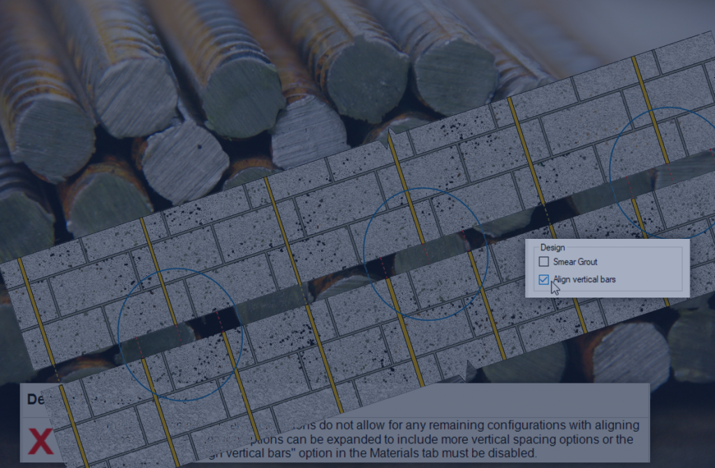
Grouting pattern and horizontal steel can be seen in the screenshot below:
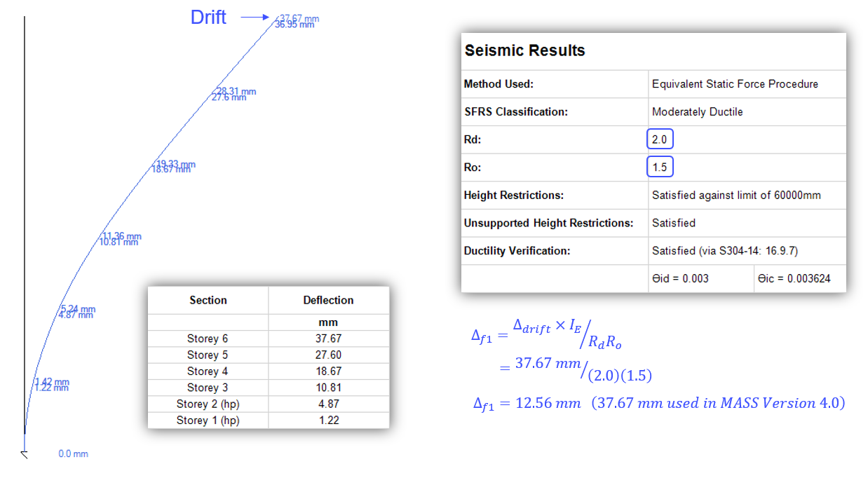
Looking at the Deflection tab, only drift is shown, which is also (incorrectly) used for Δf1 in the ductility verification. The elastic deflection can be calculated backwards by multiplying the drift at the top of the wall by the importance factor and dividing by the product of RdRo. In this example, it means a difference between using Δf1 of 37.67 mm currently, compared to the reduced 12.56 mm.
In this example, as seen in the results, demand is equal to the minimum of 0.003 (for Moderately Ductile shear walls) so this change does not affect the result. It can however declare previous design iterations as failing then they might in fact have been successful.
As a result, the ductility verification in MASS Version 4.0 is overly conservative.
Concluding Thoughts
This change will be included in the next available technical release as part of MASS Version 4.1. For the time being, users should be careful to consider whether their designs are being designed with more steel than might be otherwise required.
If there are any questions regarding this issue, design example, or whether this has an impact on a particular design you are working on, please do not hesitate to contact MASS technical support.