

Latest Software Blog Posts
How MASS Aligns Vertical Bars in a Multi-Storey Shear Wall
The method used by MASS to get bars to align is fairly complicated but gets the job done.
One early point of feedback in the Version 4.0 development process is that most engineers will not want to deal with the detailing of bars terminating in one cell and starting in the storey above in a cell nearby.
The process of aligning vertical bars was added to try and automate many of the changes that many engineers would likely make on their own after arriving at an initial design result. This article outlines the different aspects within the process of aligning vertical bars between storeys in the multi-storey shear wall module.
This post ended up being much longer than originally planned so to make it easier to locate any particular piece of information, in-page links and references are available to jump around to different sections (including examples).
Quick Article Navigation
Click below to jump ahead to:
- Main Summary.
- Selection Based Alignment (example)
- Design Based Alignment (example)
- Middle of the wall (example)
- Drawbacks and limitations
These navigation sections will be included periodically to help with navigation.
![]() Note: At any point, the icon in the bottom-right section of the screen can be used to jump back to the start of this article.(true for any page within this website)
Note: At any point, the icon in the bottom-right section of the screen can be used to jump back to the start of this article.(true for any page within this website)
Before getting into the details, it should be noted that by default, the reinforcing bars on every multi-storey shear wall design will align because each storey is designed using the same cross sectional properties. The alignment process described in this post, below, refers specifically to designs where a multi-storey design has been designed with multiple groups of properties along the height of the wall.
How to turn off the alignment option
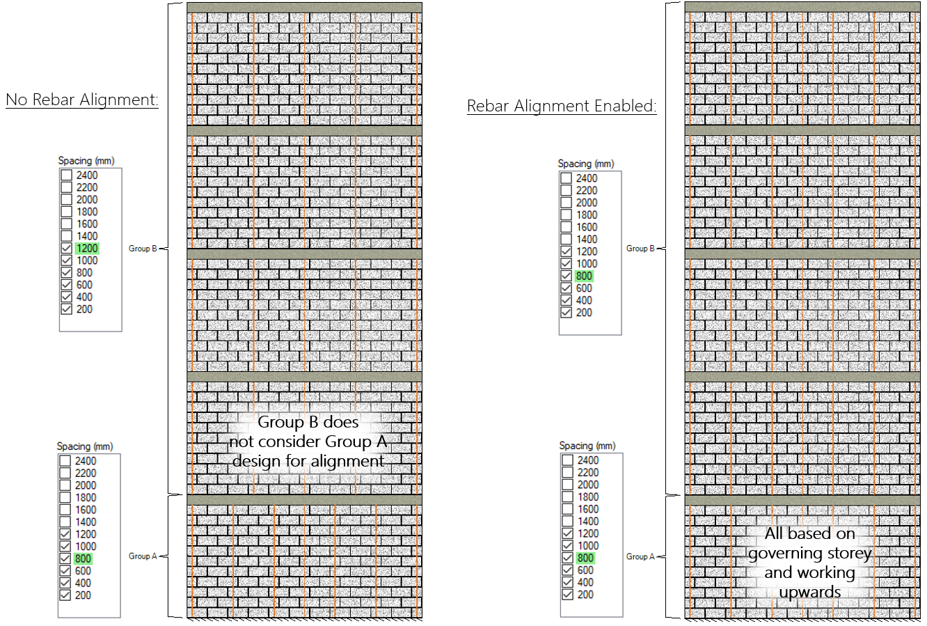
If you do not want MASS to be handling alignment on your behalf, the alignment option can be disabled and you can look at the initial results and decide for yourself how you would prefer to arrive at a design where all the reinforcement will align.
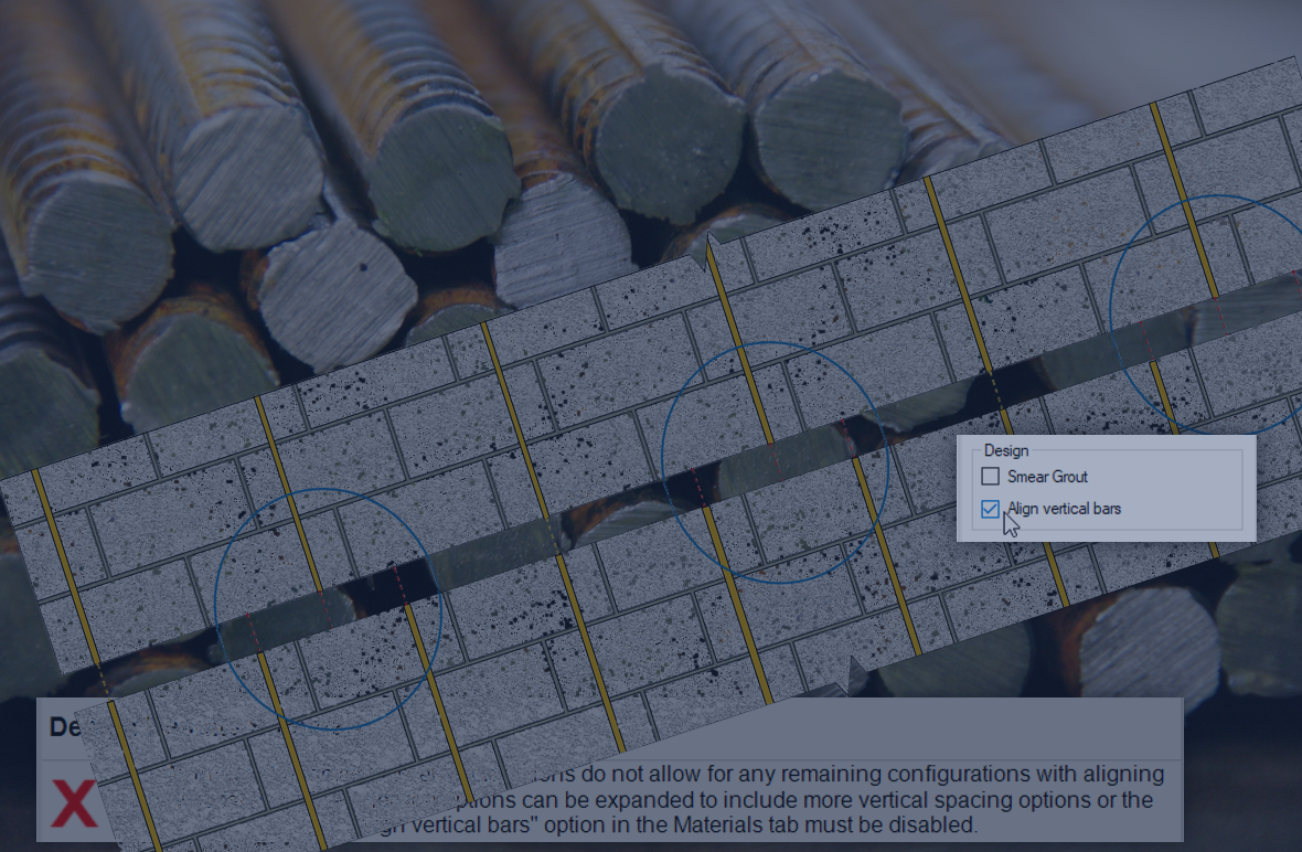
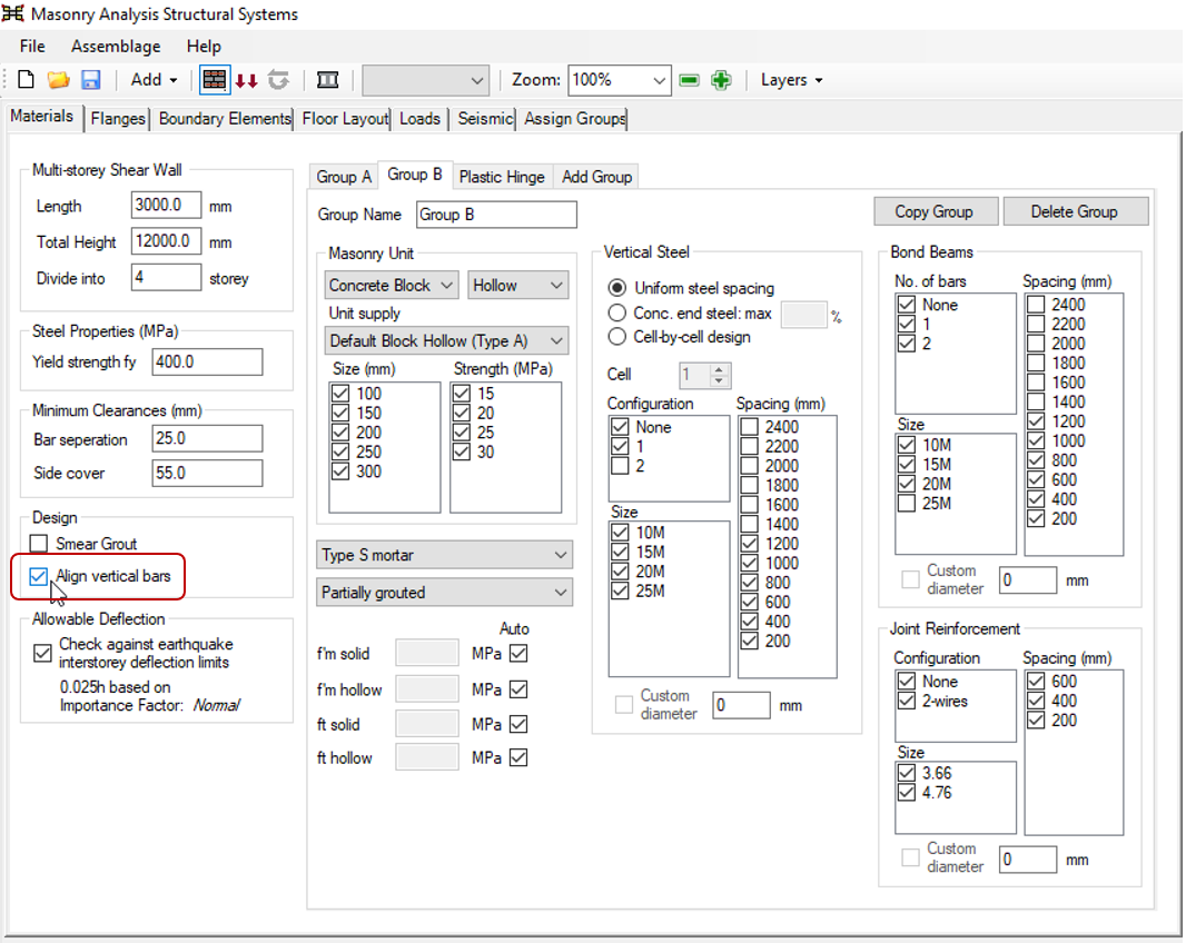
To disable the software’s alignment related processes, simply de-select the “Align vertical bars” option in the main materials input tab:
When the option is selected, MASS will attempt to align the vertical bars as much as possible. Otherwise, the software will display the first passing design found for each element of the multi-storey shear wall, regardless of the location and positioning of reinforcement.
Vertical Bar Alignment Main Summary
MASS determines vertical reinforcement spacings to align when the spacings are compared and found to be even multiples of one another (explained in further detail here). Before any design work is performed, the software first checks for disabled spacing selection assigned to any storeys to skip designs that are guaranteed to not align with other storeys (selection based alignment, click to jump). When several groups are involved, storeys at the very top will only consider designs that line up with all of the successfully designed storeys beneath (design based alignment, click to jump). If there are bars near the horizontal center of the wall that still do not align, MASS shifts bar locations and possibly adds an additional bar to ensure specified spacings and continuity along the full height (the muddy middle, click to jump). There are drawbacks and other limitations to acknowledge which are explained in more detail near the end of the article, linked here.
Before getting into the details of how MASS changes the design process within a multi-storey design, it is first useful to have an understanding of how the software compares spacings to check whether a design is considered suitable for scenarios where the user wishes for the reinforcing bars to align vertically.
The Case for Factors and Multiples
MASS relies on looking at vertical bar spacings and comparing them to each other by seeing if the larger spacing is an even multiple of the smaller spacing.
Below is a wall with vertical bars spaced every 400mm, or every other cell. If the wall constructed above is designed with vertical bars spaced at 600mm, or every third cell, note the discontinuities along the length of the wall.
In the wall with the larger spacing of 600mm, half of the bars do not align with those below. In the design below with a spacing of 400mm, two thirds of the bars do not align. This is the scenario that is being avoided using this alignment process.
Since each bar must be detailed to yield throughout the height of each wall where placed, a bar jogging from one cell to the adjacent one between floors means extra reinforcement and grout to accommodate the detail.Had the spacings shifted from 400mm to 800mm, more vertical bars align along the wall.
Similarly, a 1200mm vertical bar spacing above a spacing of 400mm gives a similar solution, where all of the bars in the wall with the larger spacing align with bar positions below.
Using this approach, MASS will only consider vertical bar spacings that are even multiples of the spacings used in designs below when the “align vertical bars” selection is selected. 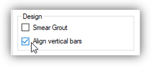
Quick Navigation
This article has been organized and written chronologically to match the process used by the MASS software. If looking to review anything covered earlier or jump ahead to a particular section, use the navigation links provided below.
Click below to jump to the following sections:
- Main Summary.
- Selection Based Alignment (example)
- Design Based Alignment (example)
- Middle of the wall (example)
- Drawbacks and limitations
Now that it has been established how MASS compared different vertical bar spacings to evaluate whether or not they align, these comparisons are used before the first design based on any design spacing options that have been disabled by the user.
Selection Based Bar Alignment
In addition to looking at the designs below to come up with a vertical bar layout, MASS also has a separate process which is run once at the outset of every design and rules out spacings that need not be checked because they are guaranteed to result in an alignment conflict.
These spacings are checked, compared, and ruled out using a similar method used in the design based alignment process, where two spacings are considered to align with each other if one is an even factor or multiple of the other.
This section outlines that process and shown an example, walking through the steps that the software takes internally to avoid these alignment conflicts.
Terminology
This article is so long and so abstract that you deserve a medal for reading it. Click here to submit your order. Throughout this post, there are many references to possible spacings, selected spacings, and acceptable spacings.
Factors are referenced here when comparing spacings to each other to determine whether or not the reinforcing bars will align.
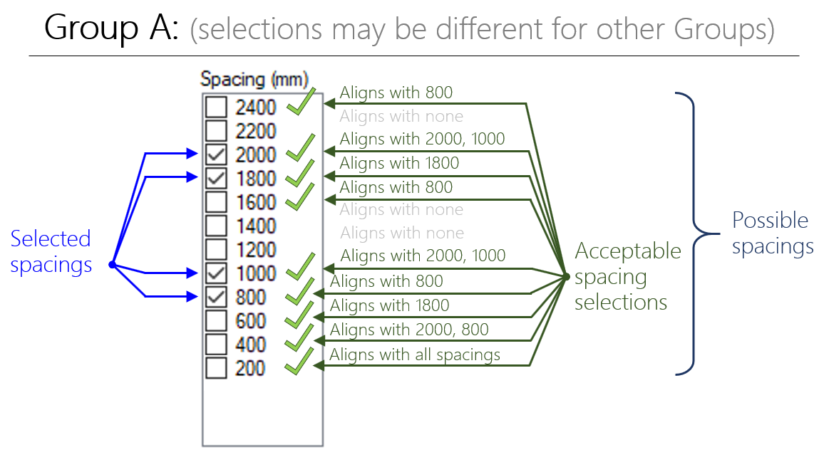
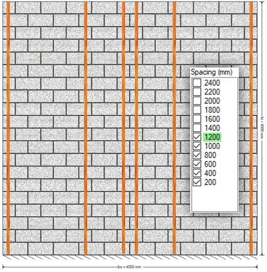
Possible Spacings refer to all of the selections that are available to have enabled within a design. In the figure above, the possible spacings start as high as 2400mm and include all the spacings down to 200mm.
Selected Spacings refer to the vertical reinforcement spacing value that are selected with a check box. By default, the spacings from 200mm to 1200mm are selected with the larger options left unchecked.
Acceptable Spacings refer to the values that will not cause alignment issues in other regions of the wall. This is based on the factor method described further down (click here to jump ahead), and is used for designs with multiple groups and de-selected spacings. For example, the figure above shows that other groups in a design cannot use the 1200mm spacing because there is no possible way to align with the group shown, where only the 800, 1000, 1800, and 2000 spacings have been selected.
These terms are used in explaining how MASS goes about aligning vertical bars
How it works
MASS starts by looking at the largest possible spacing and checking to see if any of the selected spacings are even factors of the possible spacing. If none of the selected spacings are found to be even factors, they will not align and that possible spacing is ruled out as unacceptable. This is done for all possible spacings within each group, resulting in some being classified as acceptable.
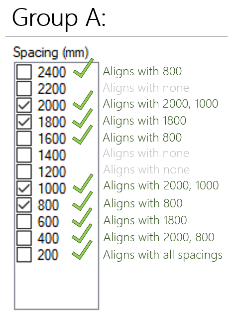
When a spacing is found to be acceptable after checking every group, it is included within the design process. A single group example is shown above and by definition, every selected spacing will be deemed to be acceptable as it is an even factor of itself. The selections are narrowed down once acceptable spacings in one group are compared to another group.
Note: When 200mm is selected for any group or storey design, no other spacings will be ruled out because 200mm is a factor is every other possible spacing, regardless of what else has been selected.
As a result, it is possible that there are no remaining spacings among the ones selected. As a result, the following error message is displayed, instructing the user to enable more selections or disable the “align bars” setting.
An easy way to trigger this error is to de-select all possible spacings except for one in Group A, then create and assign a second group, Group B, with all but one other spacing de-selected, where the second spacing does not align with the first. For example, a 600 mm spacing and a 800 mm spacing.
Group A cannot use any spacings because none of the spacings align with anything in Group B and the same is true for Group B, where none of its selections align with Group A. If this is the case for any group, the entire design fails, showing the message explained and shown above.
An example is used below to demonstrate how MASS can rule out spacings at the outset of design to arrive at an elevation with aligning vertical bars.
Selection Alignment Example
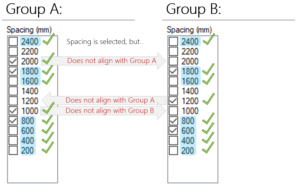
Consider the following Group A and B spacing selections, specified before a design has been run in the Materials input tab:
Before continuing reading through this post, consider guessing for yourself which of these selections will not be considered in this design. Recall how spacings are compared, covered earlier (click here to jump).
Side Note: The reasons behind why some of these options have been disabled by the user is irrelevant for the purposes of this demonstration. It has been estimated in the software development process that the majority of designs performed using MASS use the default vertical bar spacing selections for an initial design result before being further narrowed down. These selections are set purely to demonstrate the selection based alignment process.
Among the possible spacings, each selected spacing is compared to determine which is considered to be an acceptable spacing within that group. there are denoted in the figure below with a green check mark.
Once this is done for all groups, these acceptable spacings are compared between groups, resulting in a list of spacings that do not cause any guaranteed alignment conflicts with storeys above or below. These are highlighted in blue in the figure above.
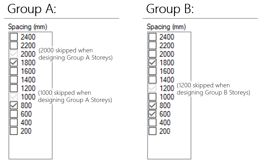
Before the first design is run, MASS compares these acceptable spacings to their selections and will rule out configurations that will not align with the other groups. in this case, Group A will not be designed using any vertical bar spacings of 2000 mm or 1000 mm because none of the Group B selected spacings will align with either of those options. When any storey designed using Group B selections, 1200 mm spacings will not be considered because they will not align with any of the Group A selected spacings.
Once this comparison has been done, MASS will know which spacings to skip to avoid these vertical bar configuration conflicts.
Since the user specified spacing selections do not change within the course of a design, this process is run just once for each multi-storey shear wall design.
Once again, if the default selections that appear in a new project are used, there is not much else that needs to be done to arrive at a design where the bars will align. This is not to be confused with the design based alignment which then takes into account the bars placed in the wall when designing other parts of the wall.
Click below to jump to the following sections:
- Main Summary.
- Selection Based Alignment (example)
- Design Based Alignment (example)
- Middle of the wall (example)
- Drawbacks and limitations
Design Based Bar Alignment
As MASS designs further up the height of a shear wall, there may be multiple transitions between design groups that will not necessarily align with one another. The process of handling this starts by considering the initial design result at the end of the Capacity Stage in the design process.The design at the base of the wall is never changed to accommodate vertical bar alignment. As a result, when the “align vertical bars” option is enabled, the bar placement further up the height of the wall can vary greatly based on the spacing used at the bottom of the wall. As covered further down in the limitations section of this article, this means that the designs are highly sensitive to the result at the base storey of the shear wall. This is not necessarily a bad thing as the benefits coming from the design uniformity and simplicity might outweigh the increase in material costs.
Note: When bar locations change within the wall, there are likely a higher number of terminating bar locations within the elevation of that shear wall’s design. There are likely additional material and construction costs that go along with the detailing of terminating reinforcing bars that are not shown within the scope of MASS. Since the software does not handle detailing, development lengths are not calculated and it is up to the professional judgment of the designer to ensure that the bars are able to yield.
For example, if an 800mm spacing is needed at the base of the wall and there are several storeys above designed using a different group with bars initially at 1200mm, all of the storeys above will be changed to also use that 800mm spacing since 1200mm and 1000mm are not even multiples of 800mm.
The software then works up the height of the wall until there is a different group of cross sectional used. This is the stage where spacings that are not even multiples of the spacing below can be ruled out since the group below has been designed. In some cases, it works out where a change in bar spacing happens to align without any needed changes but often, the software must alter the design if aligning vertical bars is desired.
With the exception of some particular arrangements of bars discussed later in this post, this is how MASS manages to design using spacings that reduce the number of bar terminations within a multi-storey shear wall design.
Design Based Alignment Example
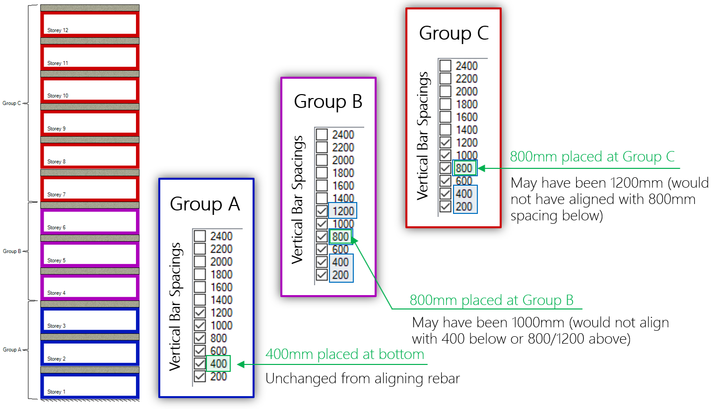
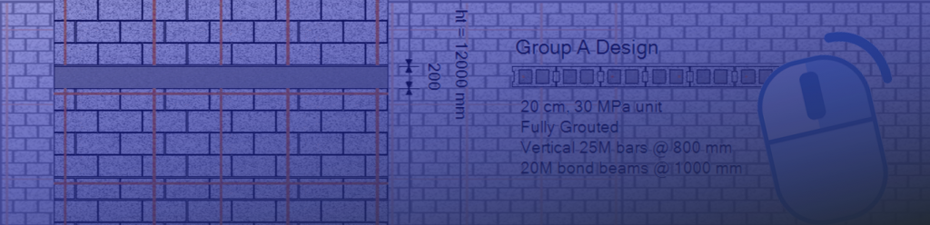
Consider the following shear wall broken into 12 storeys where three groups (Group A, Group B, and Group C) are assigned, shown below:
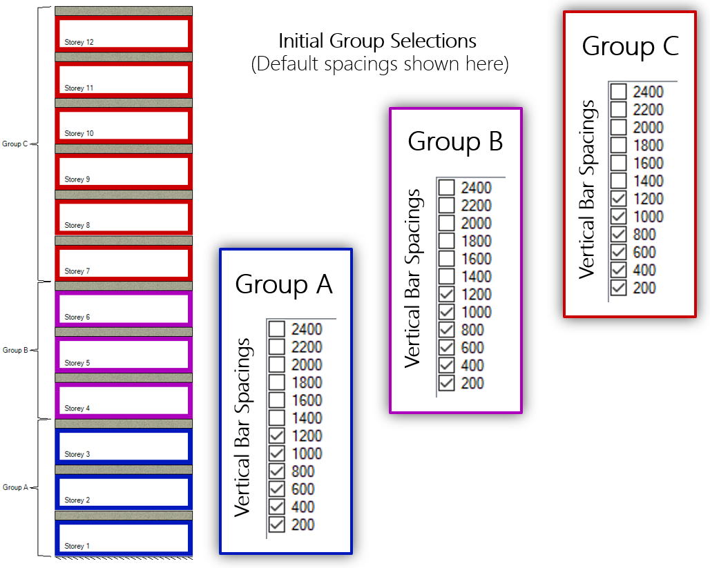
The loads are distributed and shear wall elements designed for capacity from top working down to the bottom of the wall. For illustrative purposes in this example, the first successful design is found to be using a 400mm vertical bar spacing.
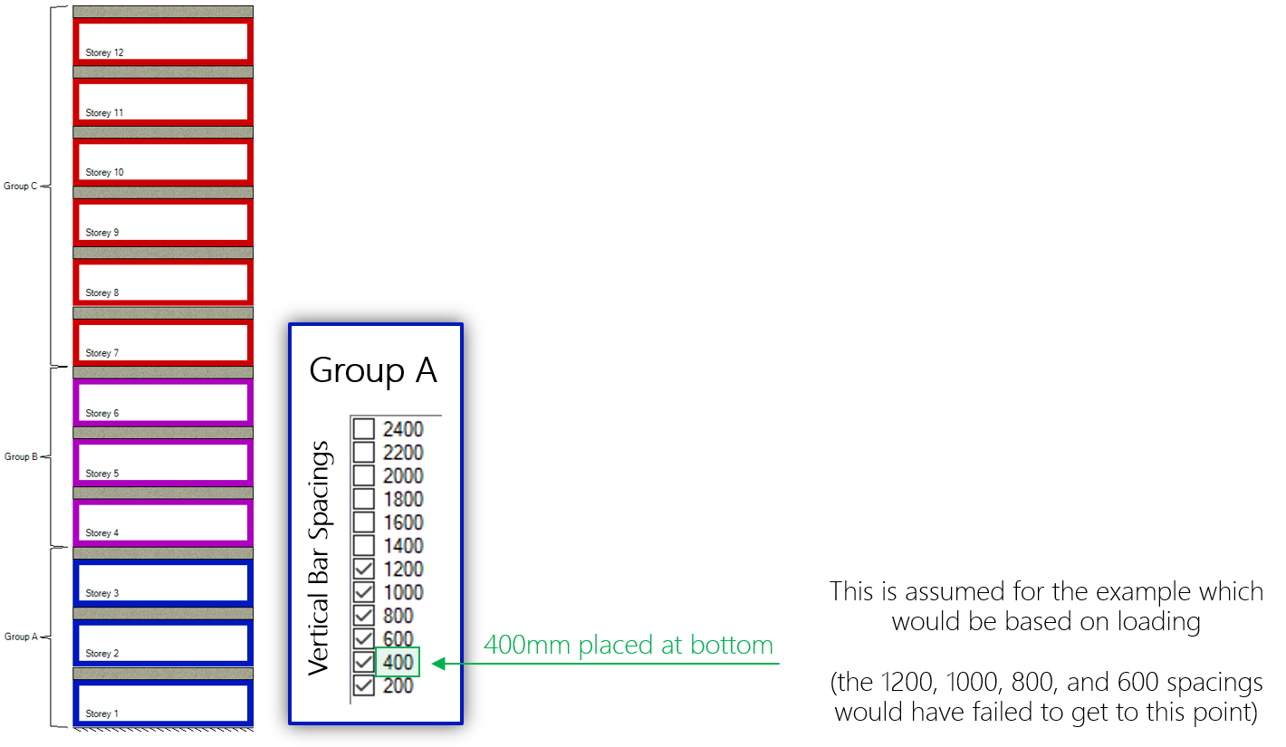
Since the bottom three storeys are all designed using the same group, the vertical bars will align as they are all using the 400mm vertical bar spacing. Note that based on the default selections shown above, MASS would have attempted larger spacings before progressing to a larger or stronger masonry unit. More is explained on this topic at the end of this post.
When designing Group B after all of the Group A storey designs are known, MASS will compare vertical spacings to see if they are even multiples of the spacing below.
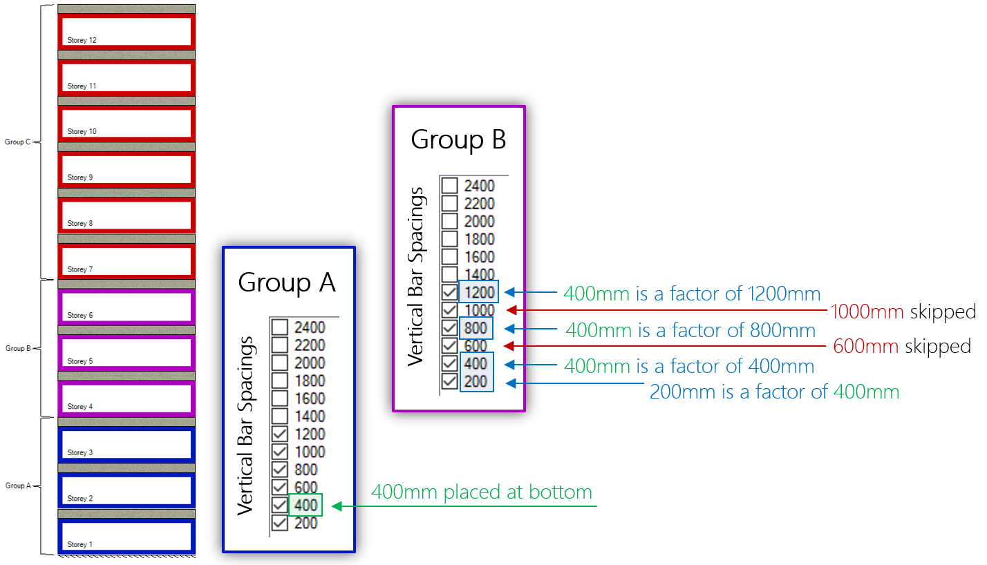
In this case, since 400mm is not an even factor of both 600mm and 1000mm, those cross sections are not considered and skipped, in favour of using a smaller spacing that aligns. For illustrative purposes within this example exercise, 800mm is the spacing selected for all of the Group B storeys.
Recall from earlier that 1200mm and 800mm will both align with the 400mm spacing in the walls below so they are each considered and 800mm is selected for design.
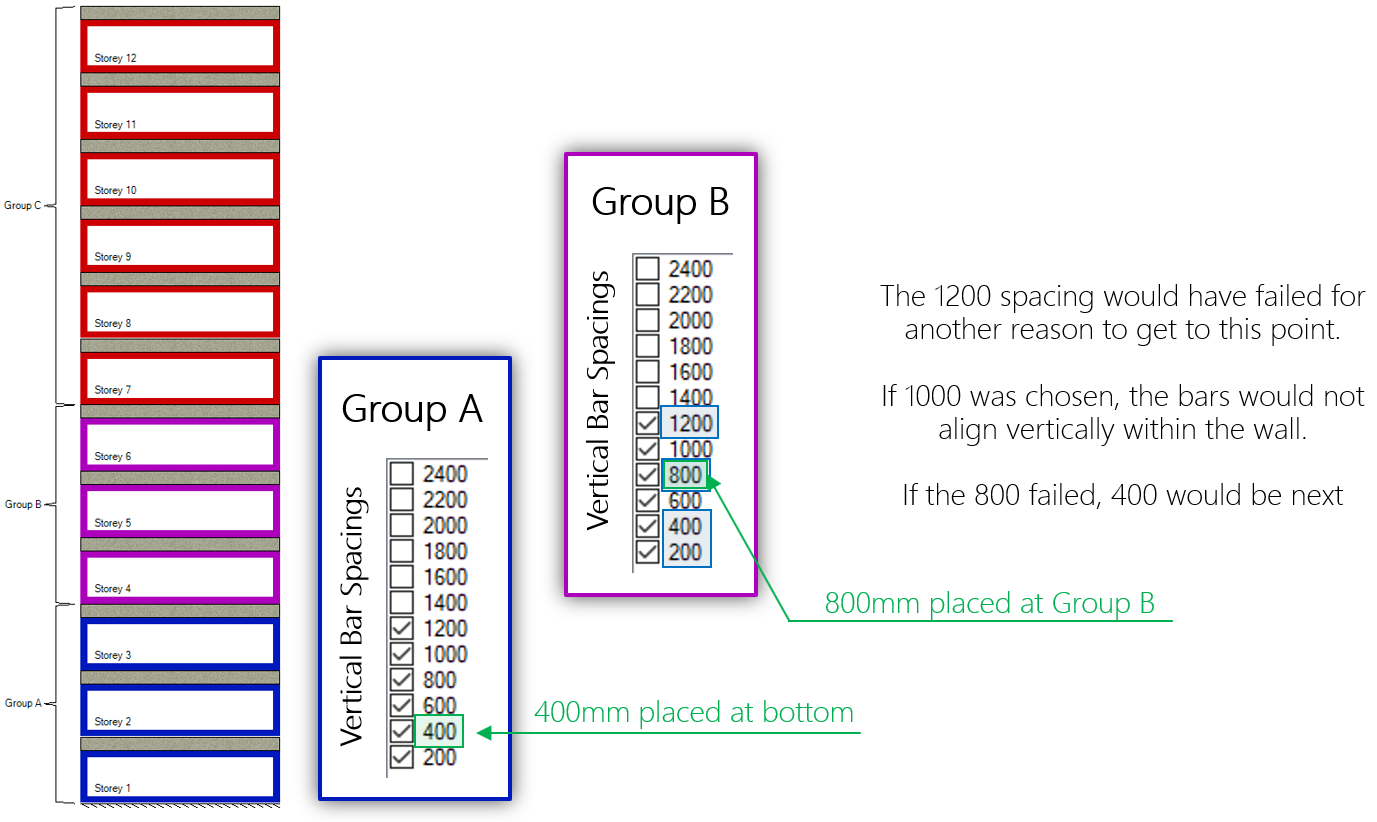
400mm spacing with 800mm above:
400mm spacing with 1200mm above:
The larger 1200mm spacing would have failed for capacity, spacing, or other reasons in order to get to a design using 800mm, which is the case for this example.
Moving to the upper six storeys (Storey 7 through Storey 12), Group C properties are assigned and considered as selections for the designs of each of these walls. Comparing vertical spacing candidates to what is present in the wall further down, 1200mm, 1000mm, and 600mm are not considered as they do not align with 800mm used below (and 400mm further down as well).
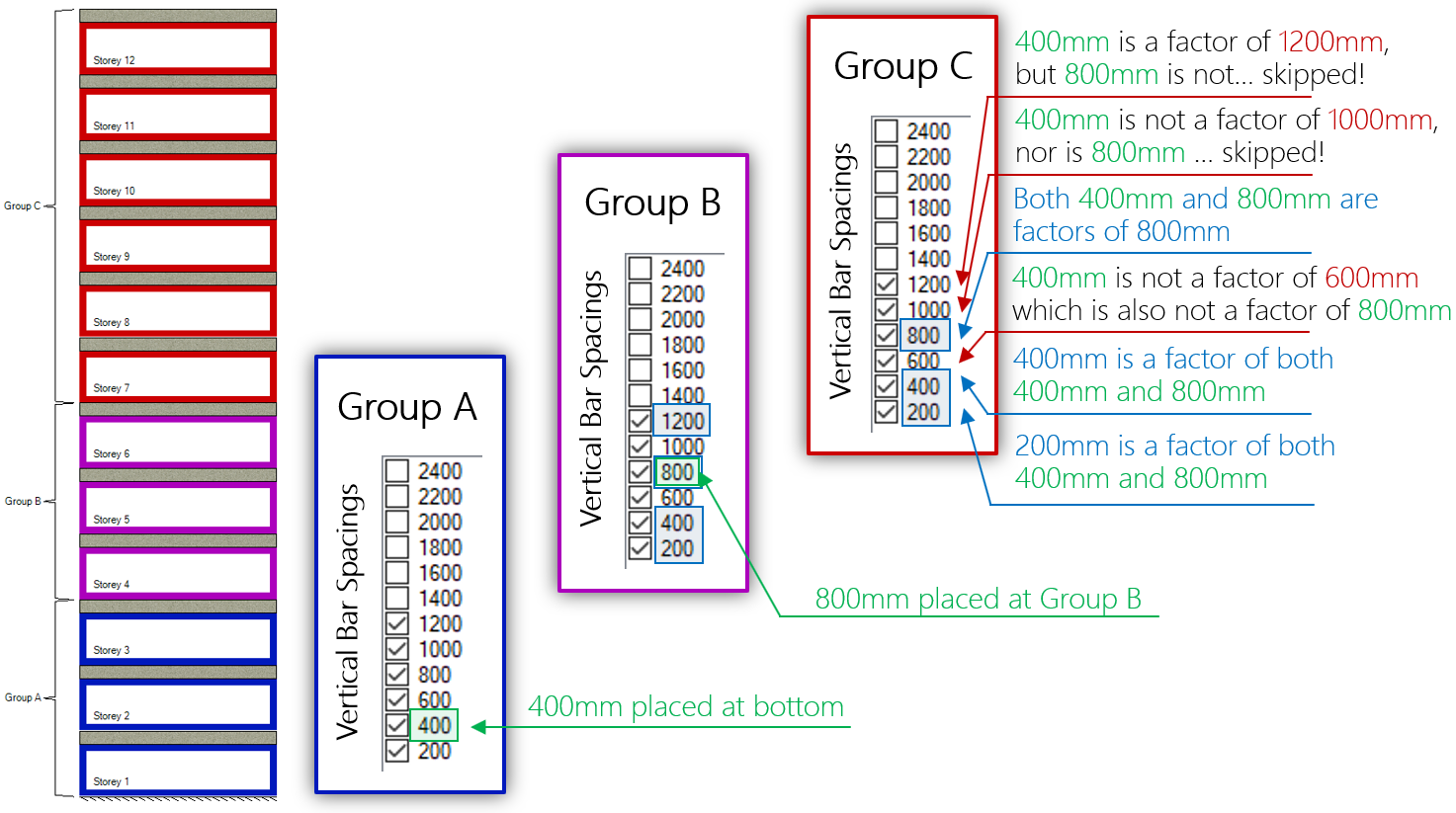
The end result is a spacing of 800mm that is selected to align with the designs further down the wall.
This example highlights a case where the design is modified to ensure that the bars will align vertically. The designer may look at this and decide that rather than have an easy transition between Groups B and C, they would prefer to deal with the bar discontinuity and use less reinforcement and grout in the Group C portions further up the wall. In these cases, it is best to perform the design the the alignment options disabled.
Based on the default selections of every spacing option from 200mm to 1200mm being selected and available from the outset as a design option, nothing more needs to be done to arrive at a design where the vertical bars will align. When the user starts narrowing down their selections for a group design used within the wall, there is another layer of logic that will ensure that the reinforcement will still align.
There are some particular combinations of even multiples of bar spacings coupled with certain wall lengths that still cause some issues in the middle of the wall.
Click below to jump to the following sections:
- Main Summary.
- Selection Based Alignment (example)
- Design Based Alignment (example)
- Middle of the wall (example)
- Drawbacks and limitations
Dealing with the “Muddy Middle” of the Wall
As it turns out, ruling out spacings ahead of time (selection based alignment) and further narrowing down the options based on what has been designed further down the wall (design based alignment) can still result in designs where there are bars that do not align between storeys. This is where MASS tweaks the bar positioning to help maintain alignment.
This is a result of how MASS places vertical bars: starting with a bar on each end cell and working inward until the specified spacing is maintained across the full length. Around the middle region of the shear wall, there might be more bars concentrated in cases where additional bars are needed to both reduce the spacing below the design spacing and also keep the wall design symmetrical, shown below:
In this example, MASS places the bars on the left and right, then moves inward in each direction by the design spacing of 1200mm, placing the third and fourth bars. Since the total wall length is 4000mm, this leaves a space of 1400mm in the middle of the wall so the software closes that gap by placing two bars in the middle two cells.
It is these added bars in the middle of the wall that can result in discontinuities between storeys when trying to align vertical bars.
Consider the following examples, where spacings that are multiples of one another but as a result of the wall length and spacings considered, offsets exist where the bars do not align.
An example MASS file can be downloaded by clicking here to view five example assemblages.
Further down this post, these examples are shown with modifications made by MASS.
How MASS aligns the bars in these cases
The software’s approach to addressing these discontinuities can be described as first scanning the length of the wall to detect these instances before changing bar locations to match the storeys below. Since all multi-storey shear wall designs have storey elements with cells that align vertically, the masonry cells themselves will always align and can be directly compared.
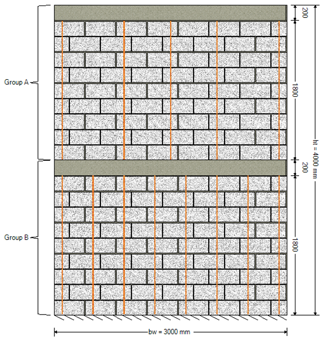
Middle alignment example
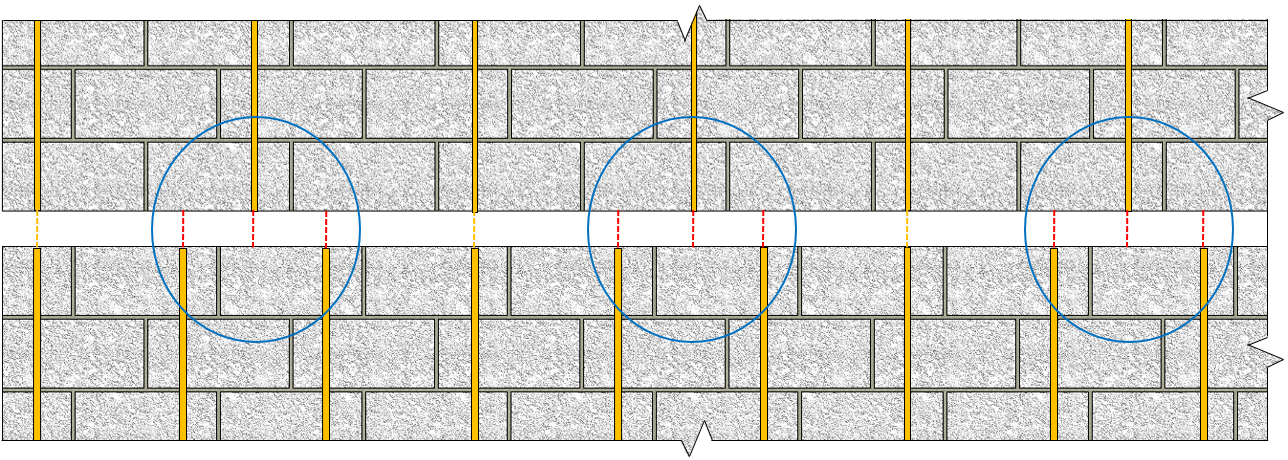
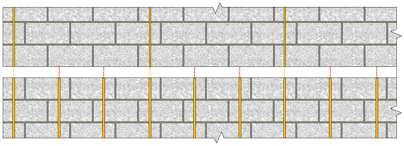
In a 3000mm long shear wall, there are 15 masonry cells total. If a 400mm spacing transitions to an 800mm vertical bar spacing, theoretically, they will align since this means half of the bars will discontinue. When it comes to actually laying out the bars within a 15 cell wall, it means a bar is placed in the middle of the 800mm spacing, directly between two bars spaced at 400mm, aligning with neither of them.
What MASS does is detect the discontinuity in the middle of the wall and adds a bar, resulting in the following:
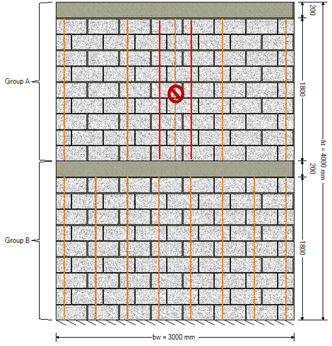
The middle bar is removed and replaced by two bars on either side. Note that the bars drawn in red are for illustrative purposes only and appear as regular orange lines within the MASS software.
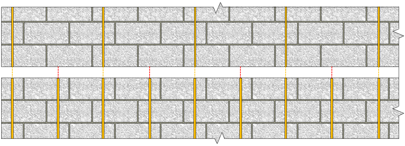
For a second example, consider a 2000mm long shear wall with bar spacings at 600mm transitioning to a spacing of 1200mm.
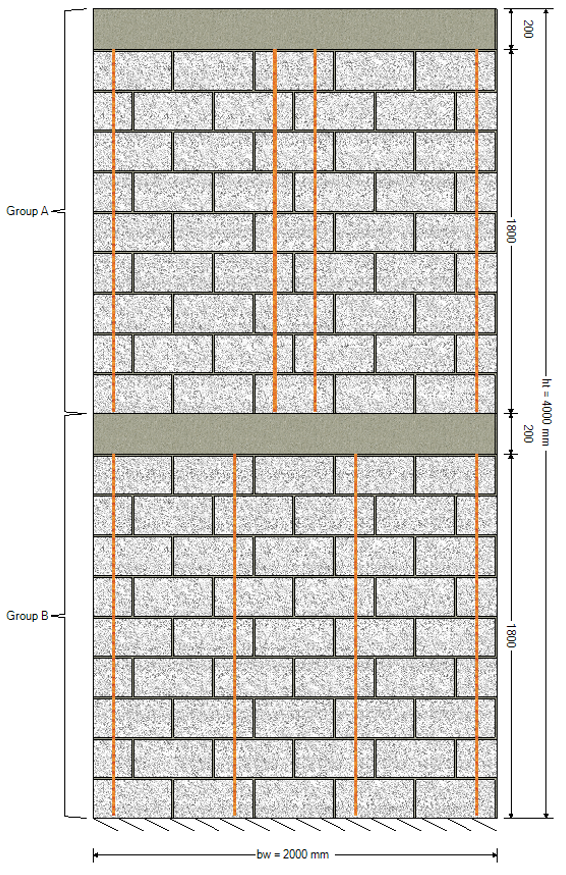
Again, theoretically these spacings should result in vertical bar alignment as 600mm divides evenly into 1200mm but since the wall length results in an effective bar spacing of 1000mm between bars in the 1200mm design, the bars end up being out of alignment. MASS addresses this by identifying the bars that do not align and shifting them to nearby cells that are continuous with the bars below:
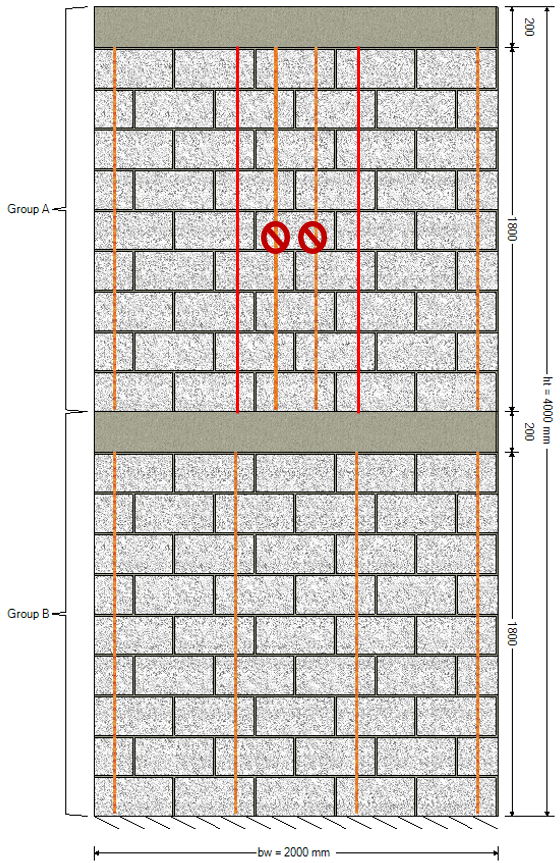
Again, note that the bars drawn in red are for illustrative purposes only and appear as regular orange lines within the MASS software.
Click below to jump to the following sections:
- Main Summary.
- Selection Based Alignment (example)
- Design Based Alignment (example)
- Middle of the wall (example)
- Drawbacks and limitations
Drawbacks (but not deal breakers)
While MASS Versions 4 and newer can do a decent job of saving more time by making sure that the vertical bars are aligned between storey designs, there are some drawbacks to keep in mind when using the feature.
The algorithm bows to no one
The first consideration to keep in mind when using this feature is that MASS has no professional judgment or common sense when determining which storeys to change when bars do not line up. There is an algorithm that will take the same approach every time a design is run, starting by ruling out spacings that do not align with other selections before moving to aligning based on designed section below, working up the height of the wall.
While this process is meant to save time and adjust the design in ways that the designer would anyway, there are always exceptions when the scope of the software is expanded. It is always important to view the initial design results with a critical eye!
MASS is not an estimator
The software will iterate through shear wall cross sections, failing, and then incrementally increasing properties until that first magical passing design is found. More can be read about the shear wall design process, linked here. In general terms, the software will use smaller and weaker cross section properties before using larger and presumably more expensive ones. This is a rigid process which does not necessarily present the most economical design as the cross section used in successful design results.
While it seems simple and straightforward that a weaker block is less expensive than a stronger one and fewer bars costs less than more, things become more complicated when choosing which properties get increased before others. The shear wall design strategy page outlines the detailed process in which the software increments selections. For example, MASS will attempt a design using every possible reinforcement configuration before using a stronger or larger block so a heavily reinforced design with a small masonry unit may be less economical compared to a larger unit with less grout and reinforcement.
This emphasizes the importance of playing around with the inputs once an initial result is displayed.
Over the influence
For typical multi-storey shear wall designs, there are vertical and lateral loads causing an accumulation of bending moment and shear forces that are greatest at the base of the wall, where it is connected to the foundation support beneath. From these common loading configurations comes the general assumption that the bottom of the wall will be the critical section that will govern the rest of the design. As a result, the changes MASS will make to a design to align vertical bars are heavily influenced by the bottom storey design. It is entirely possible that the bottom design could be slightly more heavily reinforced to allow for less reinforcement and grout needed for the storeys above.
Be deliberate when pruning down selections
As discussed earlier in the section covering the selection based bar alignment process, making changes to part of the wall may have unintended consequences for the other storeys. There are perfectly valid reasons to start disabling selections before a single design has been performed. That being said, it is advised to start off with the default selections enabled to see an initial design result before pruning down the spacing selections.
Don’t be afraid to just turn it off
The entire point of the alignment process is to save designer time from when the wall is modelled to arriving at the design that will eventually be constructed. Will it win a Nobel prize? Likely. But nevertheless, it is not perfect and will not necessarily be able to make the careful and deliberate modifications in the same way a trained design professional would.
While the personal feelings of this post’s author will be shattered, turning off the “align vertical bars” option is always available in the metaphorical tool belt of options at your disposal.
Concluding Thoughts
The “align vertical bars” feature was meant to quickly implement changes a designer would likely be interested in making immediately after seeing the first design result. While it’s meant as a time saver, it can still result in some behaviour that might not be desirable for all cases.
If there is any uncertainty regarding the reinforcement arrangement in a particular design, please do not hesitate to contact MASS technical support!

I can foresee a number of unintended consequences or confusion resulting form this feature. Once again, please do not hesitate to contact me if you have any questions at all!
(and maybe give the ‘drawbacks and limitations’ section a quick once-over just to be safe)