

Multi-Storey Shear Wall Deflection
Explaining how MASS determines the movement of a multi-storey shear wall is calculated by MASS
Contents
The addition of the multi-storey shear wall module saves time and effort compared to how these designs were done using MASS only for the individual shear wall element. While the load distribution process simply handles what was done by hand by the engineer this whole time, the addition of seismic design that considers ductility (and a ductility verification in some cases) meant that the software is now required to know the movement along the entire height – something that cannot be done by examining just one element.
A full breakdown of the method used by MASS to calculate shear wall deflection for a single element can be found here. This page builds on the contents of that article and highlights all of the differences, as well as continues the example that was started there.
From Linear Deflection to Drift
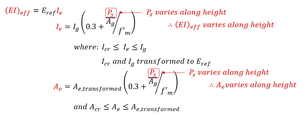
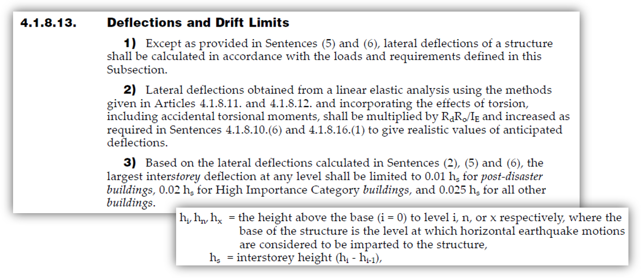
Covered in the shear wall element page in more detail, drift values are calculated by adjusting the deflection using linear elastic analysis (also using an effective stiffness) based on ductility, over-strength, and importance category:
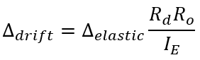
These drift limits are only checked for seismic load combinations and the linear elastic deflection is determined before drift is calculated so as a result, this transformation from deflection to drift is done at the very end, after linear elastic deflection has been calculated for the entire height of the shear wall.
All of the movements (lateral deflections and rotations) discussed in the rest of this article are elastic, with the conversion to drift values done once the elastic movement has been calculated for the entire multi-storey shear wall.
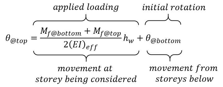
Calculating Rotation
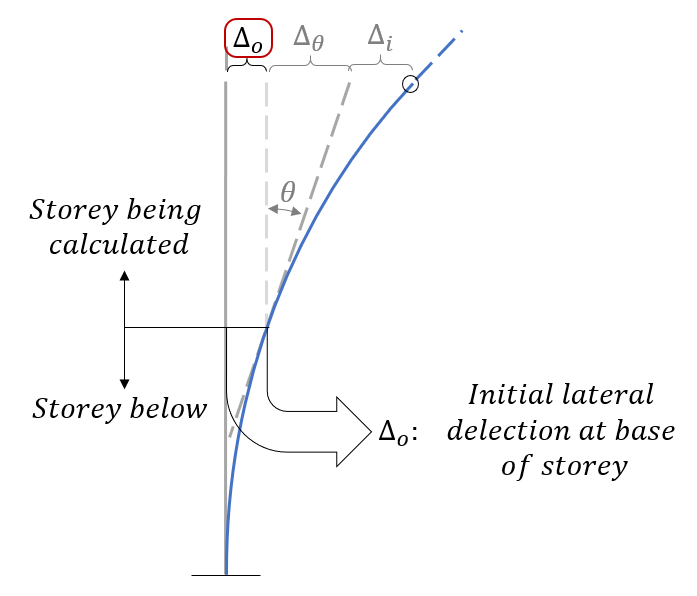
When looking at an individual shear wall element, rotations were never considered because they would not impact deflections further up the wall and the base is always fixed from rotating. For reasons discussed in more detail further down this article, rotations become a key component in impacting the deflection at the top of a multi-storey shear wall. The figure below shown the assumed deflected shape of a two storey shear wall with two sets of assumptions:
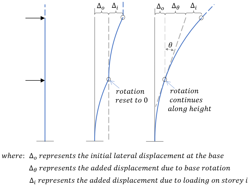
The first is the deflected shape if it assumed that there is no rotation at the base of each shear wall element. This is sometimes done for simple analysis such as in the shearline module where relative deflections are added and subtracted from one another. The second is the deflected shape where the rotation at the top of each element is carried along, further up the height of the structure. For any given shear wall element within a multi storey assemblage, the rotation at the top of that element is determined using the expression below:
This is needed in determining the effects on total deflection from movements below, discussed in the subsequent section.
Drift Effects from Movement Below
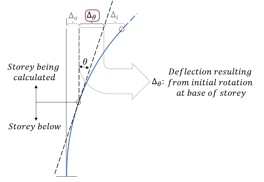
For all shear wall element designs, the end condition or base fixity at the bottom of the wall is assumed to be rigid, preventing any movement or rotation. While this may be accurate for a single shear wall, elements that are part of a multi-storey shear wall above the bottom storey are going to have some initial displacement and rotation which will contribute to the drift further up the wall. These additional drift effects can be broken down into lateral deflection and rotational elements.
Within the multi-storey deflection formula, the first term is the same as that of an individual shear wall element. A rotational term accounts for any deflection resulting from the rotation at the base of the storey being considered and an initial deflection term simply adds any deflection occurring below the storey being considered.
The deflection and rotation terms are explained further in the subsections below.
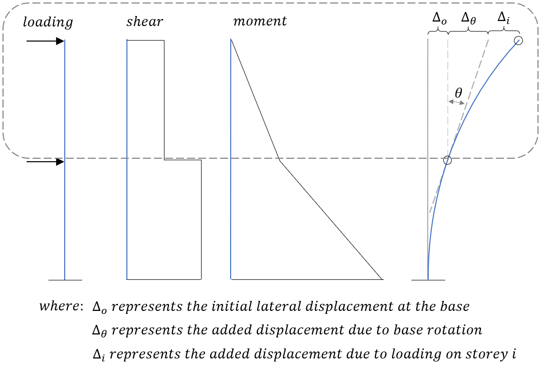
Lateral Deflection
While there is some increase in deflection over the height of a shear wall storey (based on the applied moment and shear profile), there will already be some lateral displacement at the top of the shear wall beneath. The increase in deflection from movement below the element being considered is simply equal to the amount of displacement at the base of that storey.
These values will increase as more and more deflection and rotation accumulated up the height of the structure.
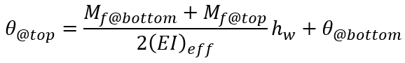
Base Rotation
Due to an incurred rotation at the top of any loaded shear wall element, this must be included in working up along the height of a multi-storey shear wall. If this were neglected then it would be the same as effectively assuming that the wall is held fixed from any rotation by the structure around it, significantly affecting the total drift as well as the stiffness used to determine how much load is experienced by that wall to begin with.
Since these rotations are expressed in radians, they are technically unit-less as one radian equals one unit of rotational arc length per radial unit length. Rather than convert these value to degrees, leaving them in radian form allows them to be applied to additional deflections by simply applying the base rotation (in radians) by the storey height.
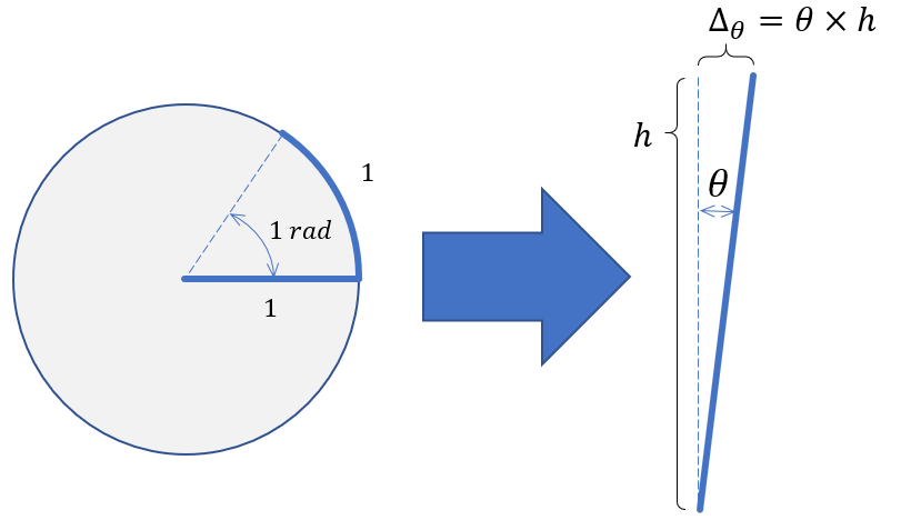
This rotational movement term also increases up the height of the wall as more load imposes more rotation to the shear wall.
Components of Multi-Storey Deflection Equation
Recall from the shear wall element deflection page where the only two aspects of applied loads (applied moment and shear at top of wall plus lateral load) will impact the total deflection at the top of the wall. Adding terms for the deflection due to base rotation plus the initial deflection at the base will result in a total elastic deflection at the top of the storey being considered.
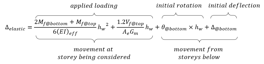
This can be done for each element, starting from the base and working up the wall to the uppermost shear wall element where the rotation and deflection at the bottom of the wall are simply equal to the calculated values at the top of the storeys beneath.
The same can be done for elastic rotations, needed for elastic deflections:
What about the stiffness of floor slabs?
For purposes of applying determining deflections, the effective stiffness of the floor slab thickness is assumed to match that of the wall resting upon that location. Since deflections are calculated between the top of each shear wall, stiffness does not need to be broken down into multiple components based on height or location for simplicity.
Added Rotational Deflection at Roof Slab
Once the total rotation and deflection for the top shear wall element has been calculated, there is a small, marginal increase in the total deflection at the top of that wall and top of the floor slab above. Although there are not any additional lateral loads or moments further up the wall, there is technically some additional marginal increase in rotation at these locations which MASS does take into account.
This is calculated by simply taking the rotation at the top of the uppermost designed storey and multiplying it by the roof slab thickness. This step is seen at the end of the example outlined in the subsequent section.
Multi-Storey Drift Example
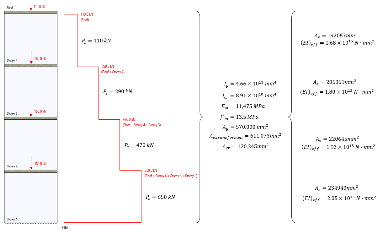
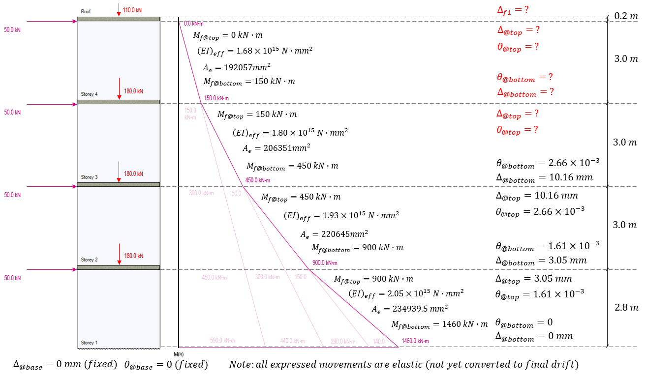
This example determines the total drift at the top of the shear wall shown below (as well as the drift at each floor in between) before checking the wall against inter-storey drift limits from the National Building Code of Canada:
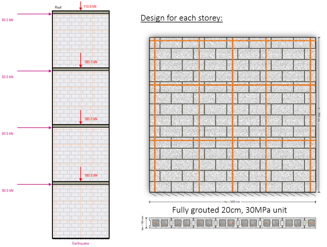
Axial loads are specified at the top of each floor and include self-weight applied from any masonry above.
The cross sectional properties, as well as drift for the top of storey 1 have already been calculated in the shear wall element deflection article. The results from that example are summarized below and this page continues from that example left off.
Note that the elastic movement profile will be calculated for the entire height before converting these displacements to drift values. These can be converted as we go but it is easy to make the mistake of mixing up elastic movement and drift values.
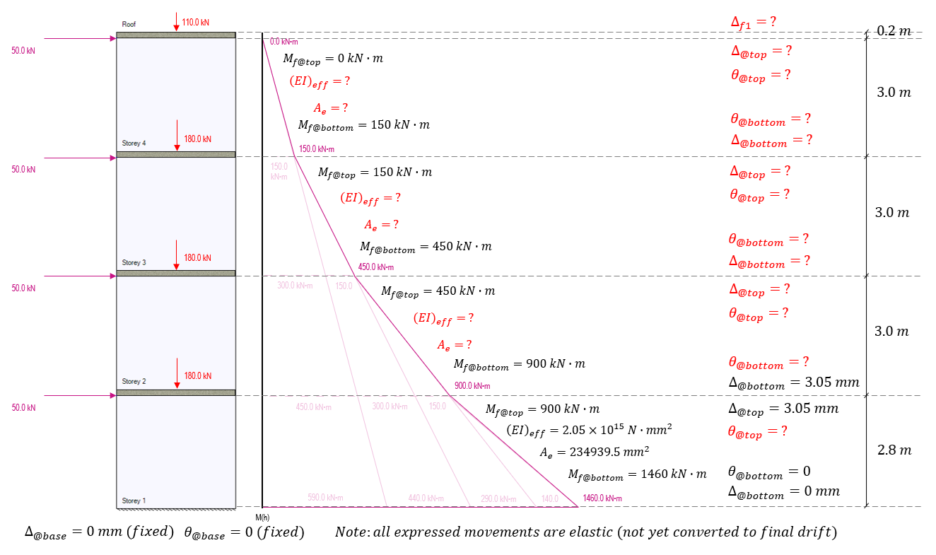
Before any deflections can be calculated further up the shear wall, the rotation must be calculated at the top of storey 1.
Recall that this is expressed in radians which is also dimensionless (unit arc length per unit radius length). This rotation is then carried to the base of the area used to calculate the rotation and deflection of storey 2.
Before proceeding with those calculations, the effective stiffness and area must be adjusted. Although the cross section is exactly the same and will have an identical cracked and uncracked moment of inertia, the stiffening effects will differ as they are a direct function of the axial load acting at those locations. This same logic applies to the calculation of the effective area.
Technically, even between floor levels, the effective bending stiffness and area will change slightly depending on the amount of self-weight acting on that location between floors. MASS takes all self-weight and applies it at the floor location so that one stiffness value can be used between the top of each shear wall element.
These effective bending stiffness and area values are calculated below for the remaining three shear wall sections as a function of the axial load for the seismic load case considered:
Recall that the physical area occupied by floor slabs between shear walls uses the effective stiffness for the shear wall resting upon it. These effective bending stiffness and area values can be used to work up the shear wall, starting from the second storey where the elastic rotation and deflection have already been determined, as shown below:
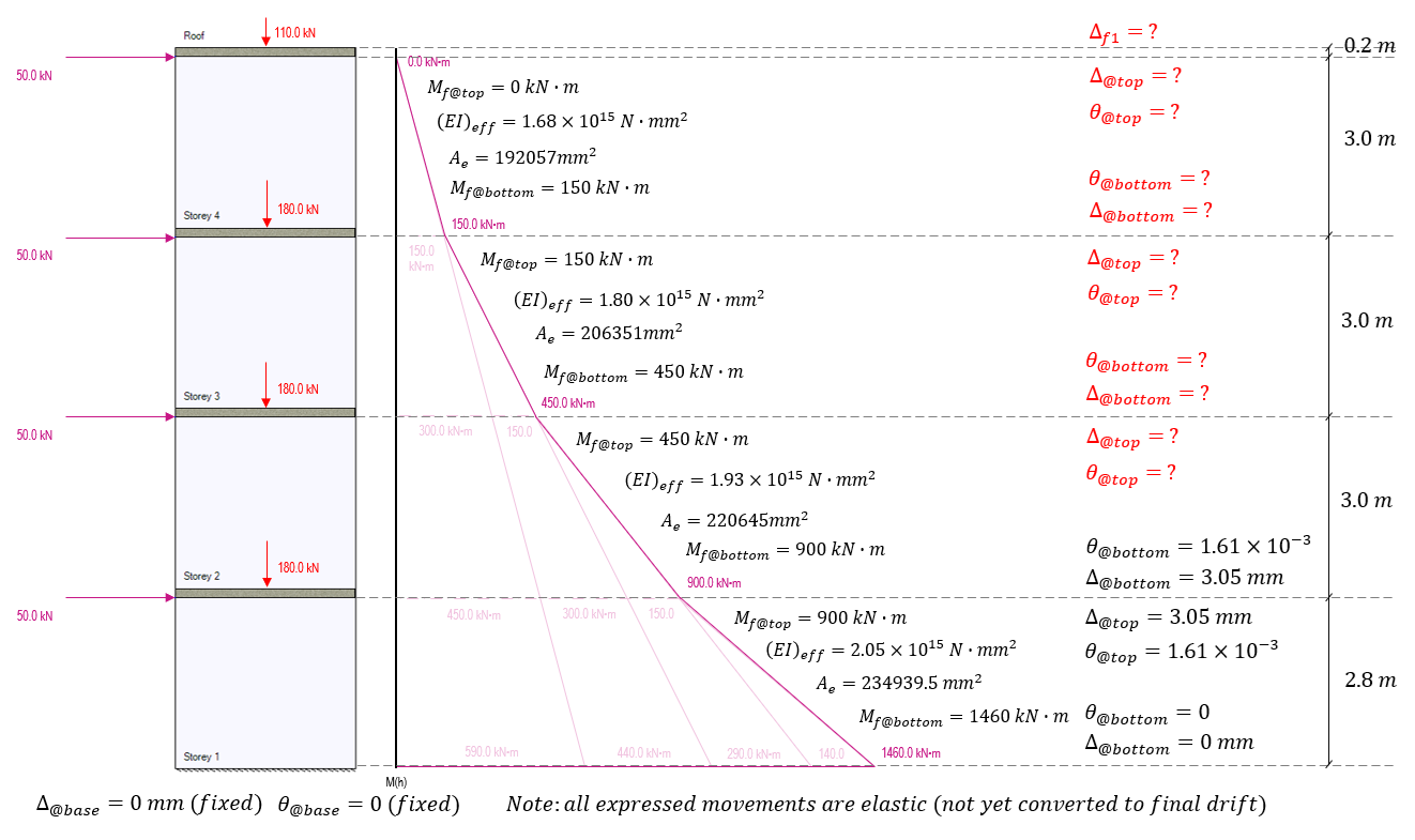
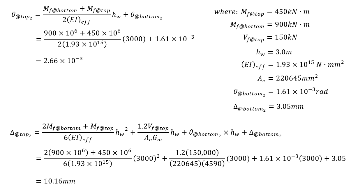
Using the Storey 2 effective bending stiffness and area as well as the initial deflection (3.05 mm) and rotation (1.61×10⁻³ rad), the deflection and rotation can then be calculated for the top of storey 2, three metres above where it was previously calculated for storey 1:
The end result at the top of storey 2 is an additional rotation of 1.05×10⁻³ radians and additional deflection of 7.11mm (2.28mm due to applied loading and the remaining 4.83mm resulting from the initial rotation at the base of storey 2). Adding this rotation and deflection at the top of storey 2 and updating the multi-storey diagram, values and remaining unknowns are shown below:
For the rotation and deflection at the top of storey 3, the applicable moments of 150 kN*m at the top and 450 kN*m at the bottom are used, as well as carrying along the rotations and deflections from the top of the storey beneath, applied to the base of the storey under consideration.
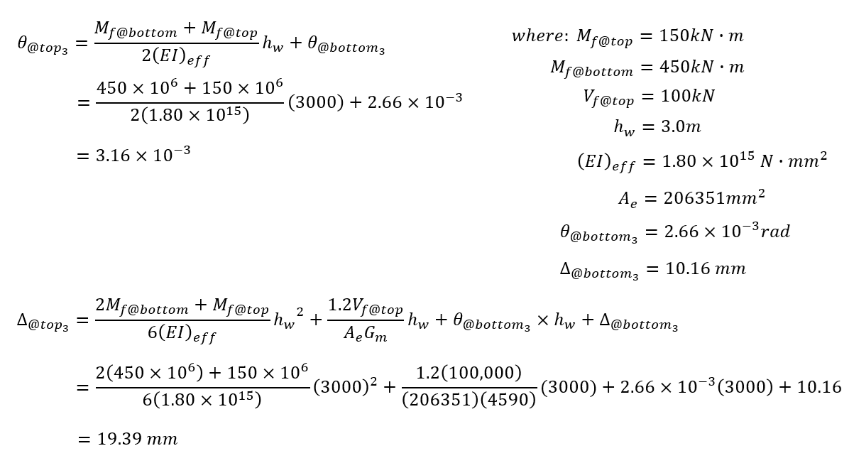
The end result at the top of storey 3 is a total rotation of 3.16×10⁻³ radians and deflection of 19.39mm (only 1.25mm due to applied loading, 7.98mm resulting from the initial rotation at the base on top of the initial deflection 10.16mm). Updating the multi-storey diagram with the values at the top of storey 3, the remaining unknowns are shown below:
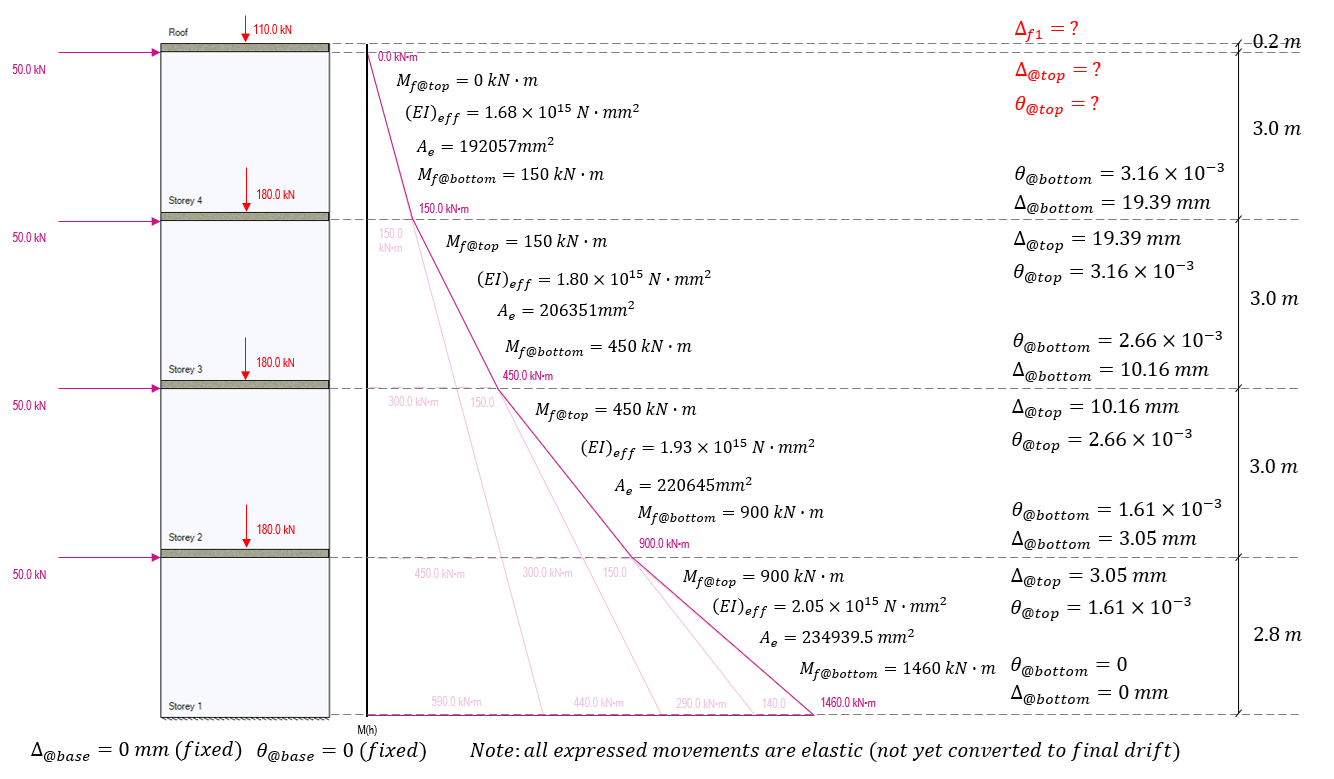
To calculate the rotation and deflection for the top of the shear wall at storey 4, the base movements are taken from the top of storey 3. Since there are no loads applied above this location and no axial loads are applied with any eccentricity, the moment at the top of storey 4 is zero, with the factored moment at the base being 150 kN*m. The effective bending stiffness and area for storey 4 calculated earlier is used to determine the movement resulting from these bending moments:
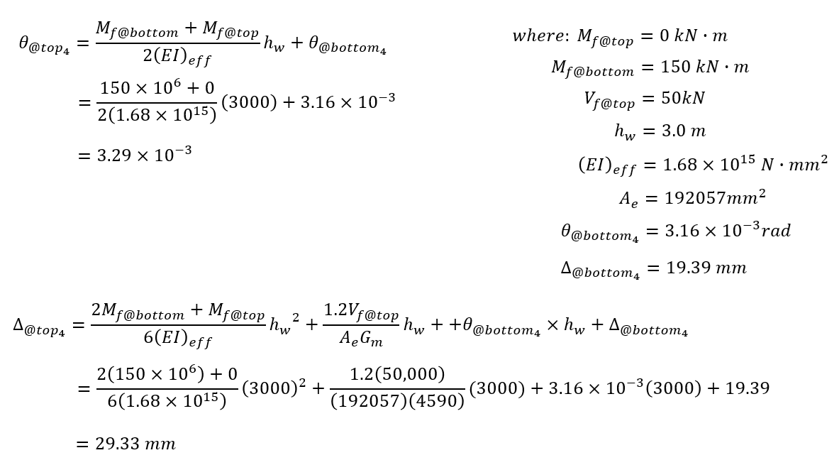
Adding these results to the diagram, it is important to note that while the elastic rotation and deflection have been calculated for the top of the uppermost storey, this does not equal the deflection at the top of the shear wall.
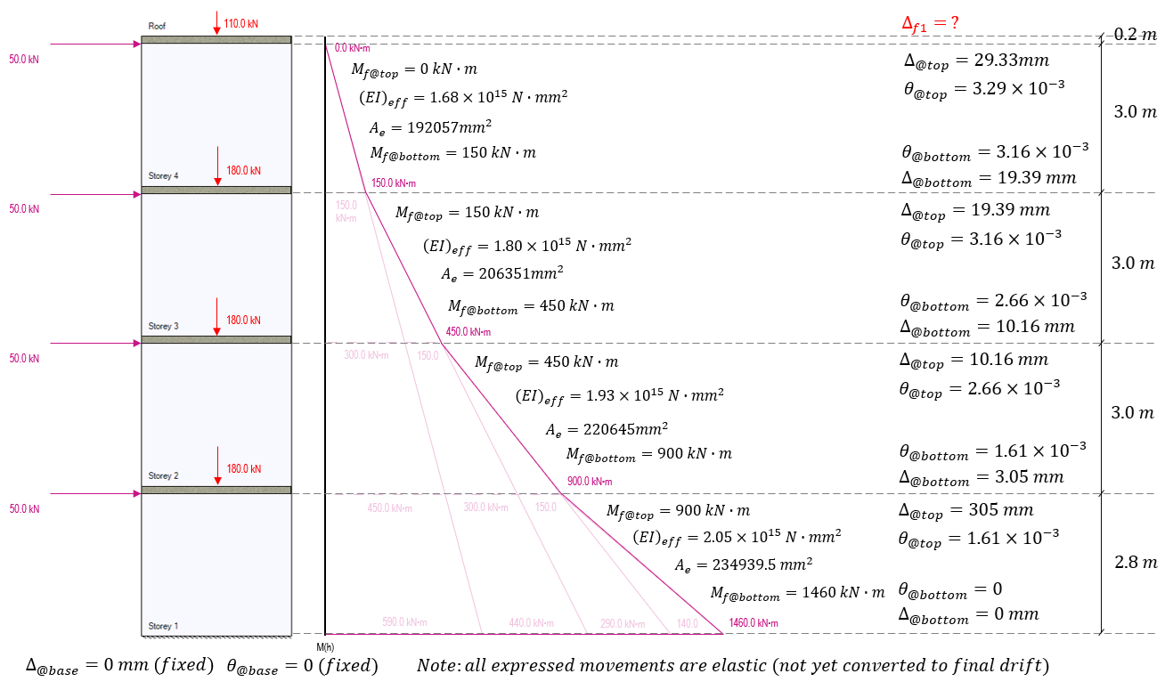
Before moving to convert these linear elastic movements to seismic drift values, the top 200mm of extra floor slab thickness must be considered. Since all lateral loads are applied at the top of each shear wall and not at the floor surface level, there is no bending moment or shear experienced at that location in this example:
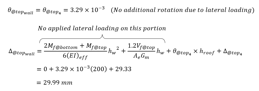
The result is an added 0.66mm of elastic deflection between the top of storey 4 and the top edge of the roof slab. This is a result of the existing rotation at the bottom of the slab being carried through the 200mm thickness, resulting in a very marginal amount of deflection.
At this point, the linear elastic movement for this load case has been determined. In order to check the wall against inter-storey drift limits as well as get the value for delta f1 needed for the ductility verification if the wall were designed as moderately ductile or ductile, the lateral drift is calculated using the same conversion method outlined in the shear wall deflection page (click to open in new tab):
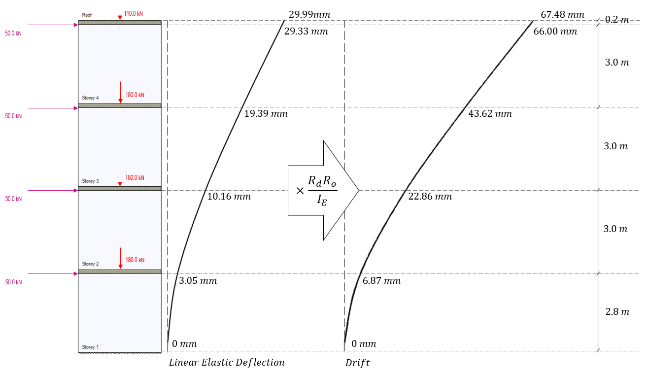
With the lateral seismic drift known for each floor of the shear wall, the difference in drift between floor, also known as inter-storey drift, can be determined and checked against the appropriate limit which is a function of the importance category.
Note the definition used for the storey height variable, hs, which is defined as the difference in height between floor locations. While the floors are placed in MASS by the top floor surface, the locations used here are at the top of each shear wall element, which is the level at which the “horizontal earthquake motions are considered to be imparted to the structure”. The inter-storey drifts as well as their corresponding maximum limits for each floor are shown in the figure below:
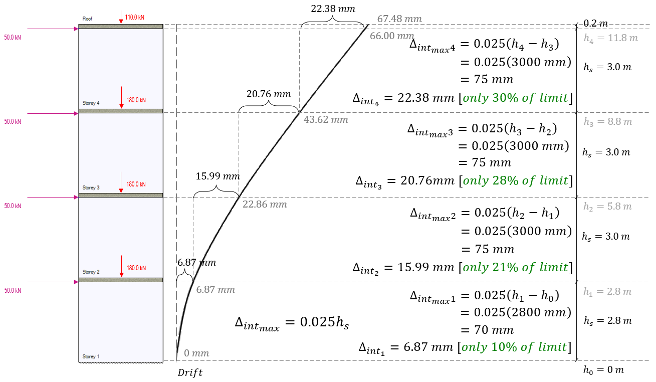
In this example, the inter-storey drift is well within the allowable limits for each floor.
Since this is a conventional construction SFRS category, a ductility verification is not required for the design of this wall. Had moderately ductile (Rd = 2.0) or ductile (Rd = 3.0) SFRS categories been applied, the ductility verification and therefore the elastic deflection at the very top of the wall would have been required. For this example, the value of Δf1 used for such a check would be 22.38 mm.
Note: a previous version of this page reported that Δf1, is based on final drift and not linear elastic deflection. This was found internally within MASS support and reported as a bug here. This page now correctly states that Δf1 is based on linear elastic deflection using modified effective stiffness properties.
Looking for more examples?
A hand calculation is available for review and is available here.
Please do not hesitate to contact MASS support with any questions
Was this post helpful?