Latest Software Blog Posts
Bug Notification: Seismic reinforcement spacings applied to all shear walls resisting an earthquake load
While most seismic requirements are triggered by the application of an earthquake load, MASS is too stringent on it’s reinforcement spacing requirements in cases of low seismic hazard index.
When bugs are reported in MASS, they are taken very seriously. In the interest of transparency, they are also posted on the constantly maintained “known bugs” page, explained in detail, and referenced on the MASS software’s welcome screen.
This issue was raised by a user who was inquiring as to the reason why they were unable to design shear walls with joint reinforcement spaced every third course at 600mm when their seismic hazard index, IEFaSa(0.2), is below 0.35. In this case, the bug represents an issue resulting in the software placing more steel than necessarily required in the affected designs described further below.
At the time of release for MASS Version 4.0, the interpretation of the seismic minimum steel spacings were that they be applied in the event of any seismic load case. Due to a change of interpretation, it has been updated based on the layout, phrasing, and structure of the relevant CSA Standards.
Disclaimer: This post is exclusively intended to provide insight into the approach taken by the MASS design software in interpreting a CSA S304-14 code compliant seismic design. It is up to the professional discretion of the designer to input an appropriate layout, boundary and loading conditions, interpret the results, and determine how they should be incorporated into their designs. As per the end user license agreement (and also recommended within PEO’s guidelines for using engineering software), a tool cannot be considered competent and reliance on a tool does not relieve the user of responsibility.
The issue is summarized below with a more detailed outline with any other required background information available further below. If there are any questions regarding this issue, please do not hesitate to contact MASS technical support.
Summary
Any shear wall element designed within MASS currently has all horizontal reinforcement checked against seismic spacings regardless of seismic hazard index when an earthquake load is applied to the wall.
This is also the case for shearline modules and multi-storey shear wall designs, as they rely upon the shear wall element module for the design work.
See the example further below in this article for a practical demonstration of a design where this change will affect final design results.
A future technical release will address this, checking the vertical and horizontal reinforcement against spacings only the seismic hazard index required. This will be addressed in the release of MASS Version 4.1.
Background information
With the release of MASS Version 4.0 which expanded the scope of the software to handle many earthquake related design provisions, an entirely new seismic tab was added to shear wall input
When designing any shear wall element (also used for shearline and multi-storey designs), MASS applies all earthquake design related checks and calculations from CSA S304-14: 16 (Special provisions for seismic design) based on whether or not an “Earthquake” type load is applied to the wall. This criteria used as the over/under limit to apply any checks contained within CSA S304-14: 16 unless other conditions including SFRS ductility or maximum compressive strain included in the standard’s verbiage.
Currently (as of publishing this post where Version 4.0 is the most recently released edition), CSA S304-14: 16.4.5.3-4 requirements are checked using this criteria for all seismic load cases. This criteria is what is being changed for the next technical release.
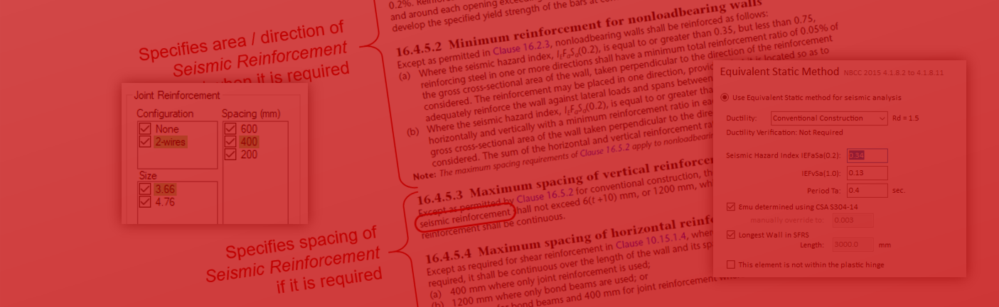
The change of interpretation comes down to what exactly is considered seismic reinforcement and the structure of the relevant clauses from CSA S304-14: 16.4.5, shown below:
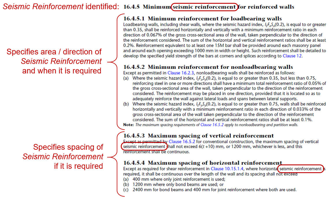
Note the term seismic reinforcement in the main heading which implies that the clauses within are specific to this classification of reinforcement. While clauses 16.4.5.3 and 16.4.5.4 do not reference seismic hazard index values directly, they are specifically applied for steel placed in the wall as seismic reinforcement. These limits do not apply for sites in which the seismic hazard index is below 0.35 if the steel is not needed to resist seismic loads.
By this new classification, horizontal steel placed in a wall resisting earthquake loading is not necessarily considered to be seismic reinforcement. Only walls with a seismic hazard index large enough to trigger the minimum requirements from CSA S304-14: 16.4.5.1-2 contain reinforcement that is classified as seismic reinforcement and are subject to the requirements of CSA S304-14: 16.4.5.3-4 if the steel is needed specifically to resist Earthquake type loads. For example, a shear wall may require joint reinforcement to resist in-plane wind loading so as long as the seismic hazard index is below 0.35 and the joint reinforcement is not required for a seismic load combination, the reinforcement can be spaced at 600mm instead of every other course.
Note that this definition is solely meant for interpreting the reinforcement spacing requirements within CSA S304-14. There could be other reasons or contexts for referring to “seismic reinforcement” in a masonry design and this article, reasoning, or interpretation is not meant to addressing these other cases.
Based on this interpretation, even for seismic load combinations, designs with low seismic hazard index values may only be subject to the requirements concerning minimum steel outside of clause 16.
Design Example
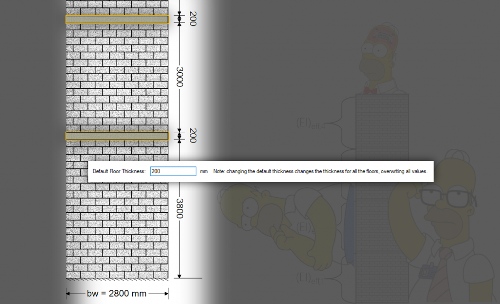
Consider a 3 m long, 4 m tall shear wall conventional construction shear wall constructed using 15 cm, 15 MPa units resisting a 150 kN dead load and 45 kN laterally applied “Earthquake” type point load. the wall is partially grouted with vertical 10M bars placed every 800 mm and the seismic hazard index for the site is 0.34.
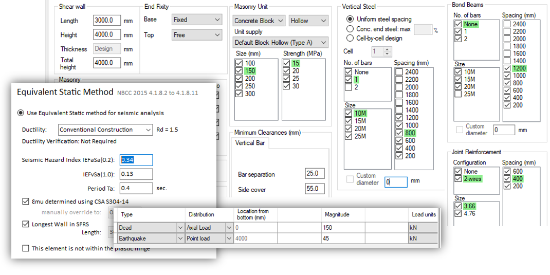
When designed under load combination 1.0D + 1.0E, MASS does not place the 0.067% reinforcement in both directions as the seismic hazard index is below the threshold of 0.35, in accordance with CSA S304-14: 16.4.5.1 (classified as loadbearing since the shear wall is resisting an externally applied axial dead load). In Version 4.0, the software does still restrict the spacing of joint reinforcement to being placed every other course at a spacing of 400mm.
While the joint reinforcement is required to resist seismic loading (factored shear scaled up to consider seismic effects is 77.9 kN compared to the masonry resistance of 60.8 kN), it should not be considered seismic reinforcement and 16.4.5.4 (a) should not be applied.
A spacing of 600mm is otherwise permissible, so long as all other requirements are satisfied.
Concluding Thoughts
This change will be included in the next available technical release as part of MASS Version 4.1. For the time being, users should be careful to consider whether their designs are being designed with more steel than might be otherwise required.
If there are any questions regarding this issue, design example, or whether this has an impact on a particular design you are working on, please do not hesitate to contact MASS technical support.