Latest Software Blog Posts
How to model individual storeys of a multi-storey shear wall within MASS
In the absence of a true multi-storey MASS module (Update: added in V4.0), there are steps that can be taken to use MASS effectively for these types of designs
This article originally was featured on the MASS Software Blog, formerly hosted on the software section of the Canada Masonry Design Centre website. CMDC is the authorized technical service provider for the MASS Software
Note that these types of designs can not be dine directly using the multi-storey shear wall module, added with the release of MASS Version 4.0.
The MASS software is a useful tool for designing the individual structural elements of a masonry building. While there is a shearline module for simple, single-storey elevations, there is no such equivalent when it comes to multi-storey shear wall design (yet). It is left to the designer to model each element of their shear wall within MASS in a way that accurately represents its behaviour. This article will touch on a few of the major aspects that come up when using MASS for multi-storey designs.
To jump straight to a specific aspect, click the heading links below:
Click here to jump straight to the summary.
Load Distribution
Before diving into the multi-storey specifics of shear wall design, it is useful to first recall the scope of the shear wall module in MASS.
Shear wall module scope:
The shear wall module in MASS designs an individual shear wall element for in-plane moment and shear based on the loads that are applied to that individual element.
The shear wall module can be used for multi-storey buildings so long as the designer has taken into account the various ways in which a shear wall element interacts with the structure around it.
This includes:
- The accumulation of axial loads applied above the storey being designed
- The accumulation of lateral loads applied above the storey being designed
- Any overturning moments resulting from lateral loads applied above the top of the storey being designed
Example Exercise
Consider the example below, where the second storey of a four storey shear wall is being designed using MASS. In order to design the second floor shear wall element, all loads must be distributed to the top of the wall from all of the walls above. Each storey is 4m tall and all dead loads include self-weight.
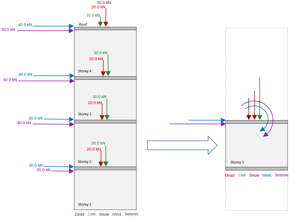
Before expanding the solution, it may be a worthwhile exercise to calculate the solution yourself to test your skills.
So, how did you do?
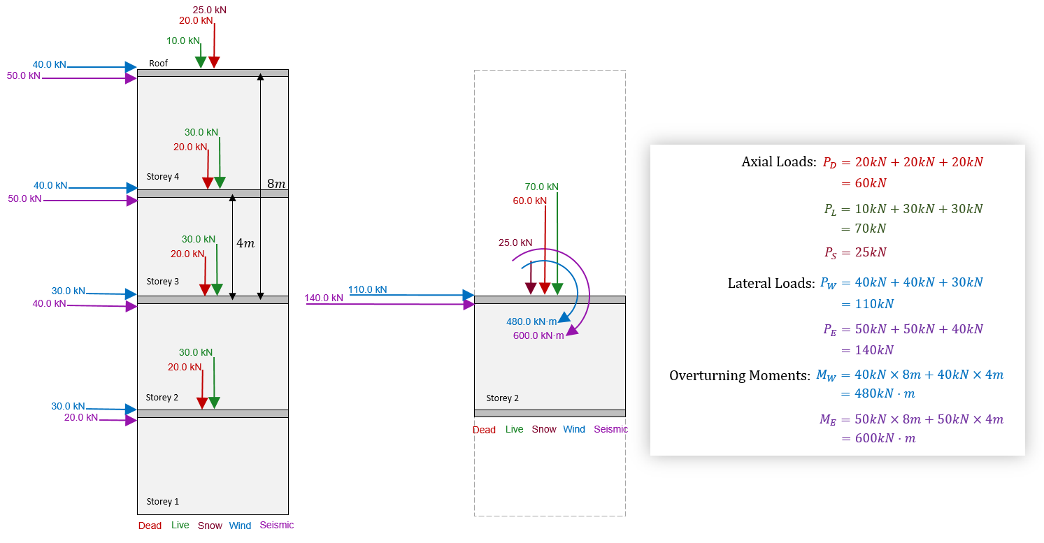
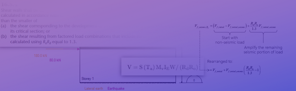
The axial loads applied to the top of each storey is simply the sum of all loads applied to that floor and above. Note that this would also include the self-weight of the walls if they had not been included in the dead loads. Lateral loads are handled in the same fashion where the load applied to a single storey is the sum of all loads applied at and above the storey being considered. Overturning moments are simply the applied bending moment resulting from an applied load being applied some distance above the top of the wall being designed. In this example, the lateral loads applied at roof level are 8m above the top of storey 2, and the loads applied at the top of storey 3 are 4m above, which would be the corresponding moment arms used for this calculation.
Note: All axial loads are assumed to be placed at the centre of the wall and evenly resisted by the full cross section (no load dispersion is considered within the section). In cases where axial loads are applied with some eccentricity, this can be accounted for in MASS using an applied moment with a moment arm equal to the eccentricity of the load.
While distributing loads makes up the majority of the work needed to design multi-storey shear walls in MASS, there are still three other important aspects to consider.
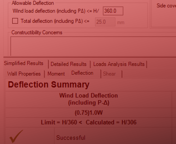
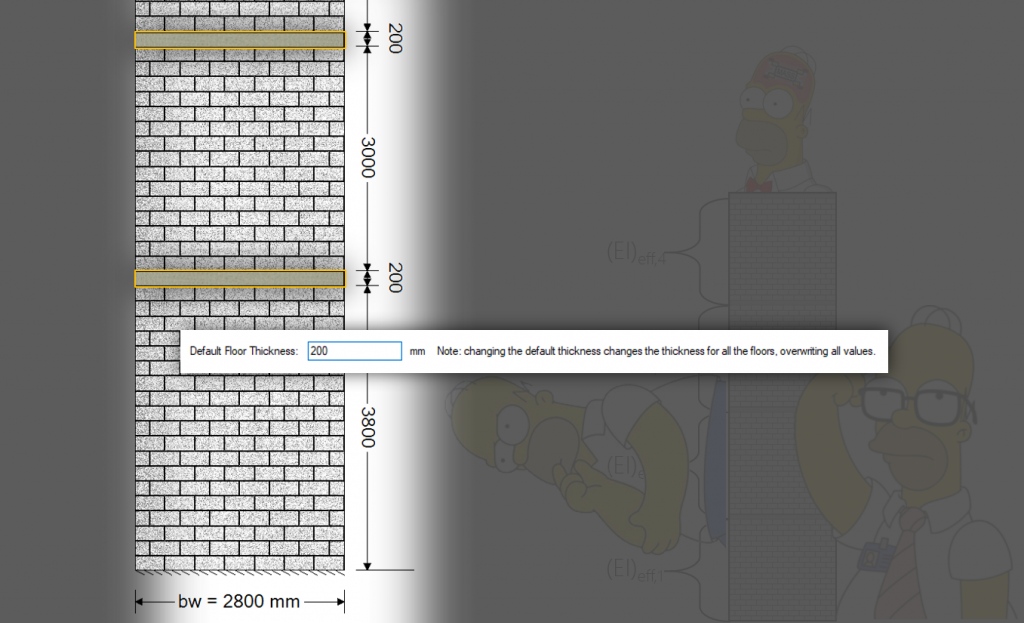
Total Height
It is possible that while the full shear wall is not considered “squat”, an individual storey may have a height to length aspect ratio less than 1. In this case, it is important to change the total height to match the height of the full shear wall so that MASS doesn’t treat the individual storeys as squat shear walls. By default, the total height is set to the same value as the shear wall height so if it is unchanged, there may be an unnecessary reduction in moment resistance.
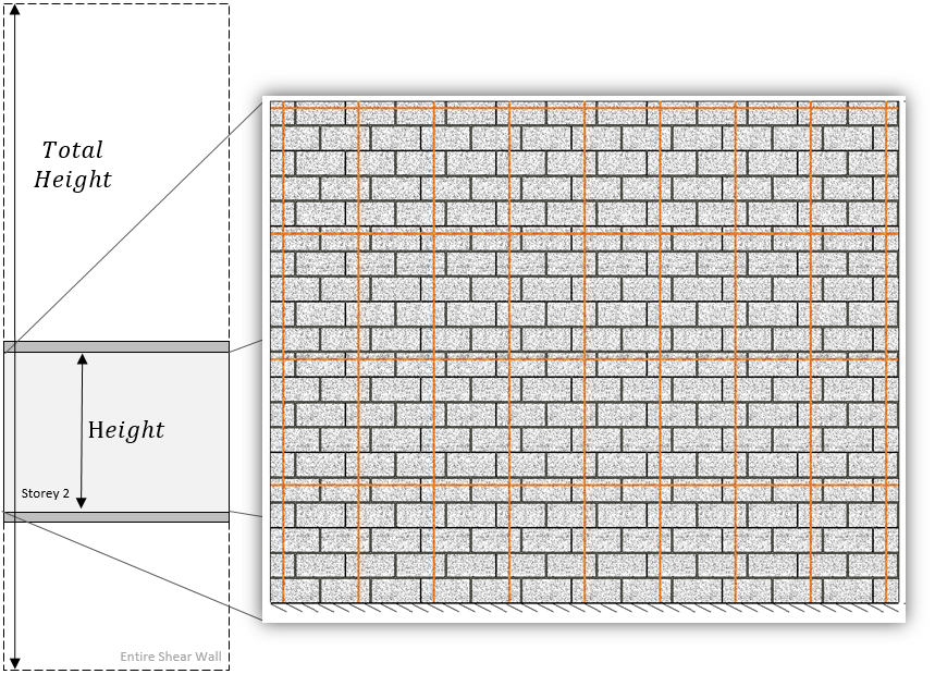
A full article explaining the difference between “Height” and Total Height” can be found here, including examples showing between 15% to 24% of moment resisting performance losses for not taking the total height into account.
End Fixity
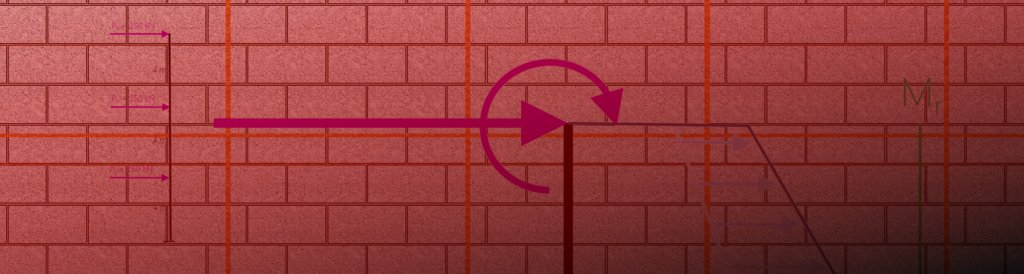
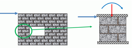
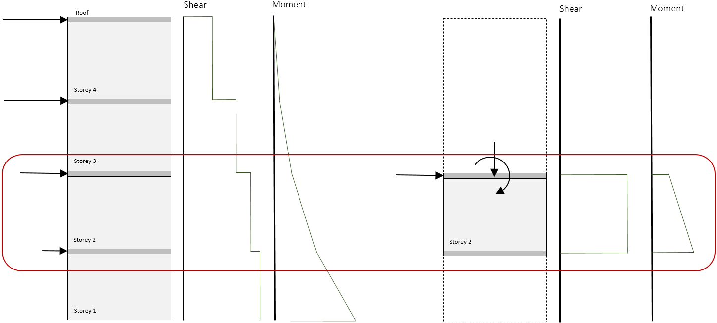
When looking at a shear wall element within a larger shear wall, the objective is to take all aspects of being part of a larger shear wall into account. While there is an option in MASS to fix the top of a shear wall from rotating, the effect on the design can be seen in the difference in bending moment profile below:
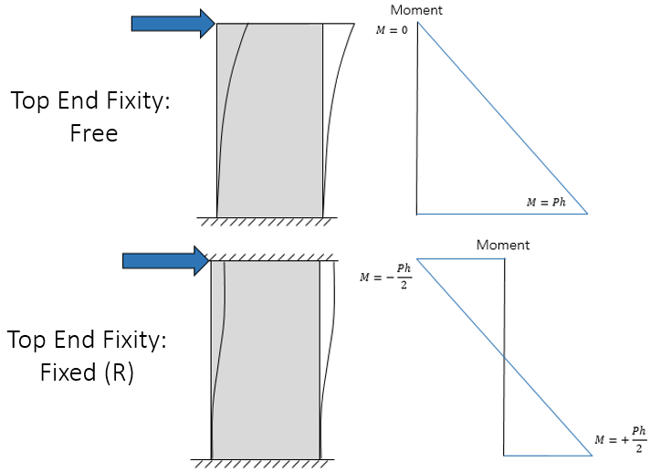
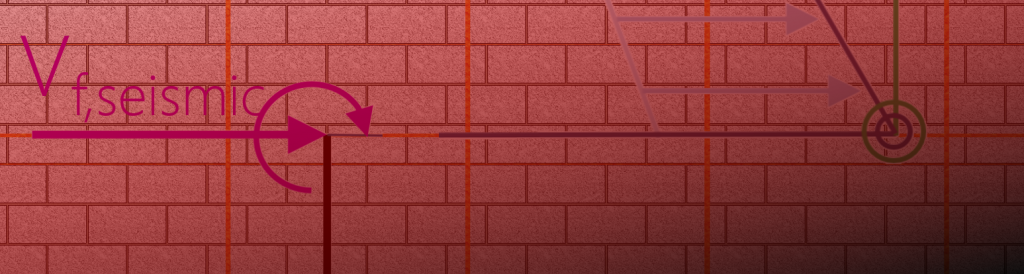
Applying a rotational fixity at the top of the wall effectively divides the moment between the top and the bottom of the wall’s supports. While the “Fixed (R)” end condition was added to MASS for the purpose of shear wall designs with significant masonry above which prevent rotation, the scenarios where it is appropriately used would more closely resemble what is pictured below, taken from section 5-7 of the MASS Help files:
As a result, there is no need to change the end fixity of the top of the shear wall, as long as the loads have been properly distributed. Using the cantilever configuration for a multi-storey shear wall , it can be designed element-by-element, accurately designing each storey for the same shear and moment profile as would be used if the full multi-storey shear wall were designed at once.
Only by using the default cantilever fixity selection can an individual storey be adequately modelled without having to apply additional loads to cancel out the effect from a fixed top rotational end condition.
Summary
To quickly summarize, there are three main things to consider when designing a multi-storey shear wall using MASS:
- Load Distribution: all loads not applied directly to the storey being considered must have their effects included. In particular, the accumulation of axial loads, lateral loads, and overturning moments due to loads applied from storeys above.
- Total Height: To avoid being penalized for squat shear wall moment arm reductions, be sure to change the total height in order to accurately reflect the full height of the wall.
- End Fixity: While it may at first seem reasonable to factor in the rotational stiffness from storeys above by changing the top fixity to Fixed (R), it will not result in a moment profile that accurately reflects the moments experienced by the storey in question. The default cantilever selection with properly distributed overturning moments is a more appropriate selection.
The MASS software is a product of a joint partnership between CMDC and CCMPA. CMDC is the authorized provider for MASS Technical Support.