

Boundary Elements
Adding Boundary Elements to a Shear Wall Design using MASS
Contents
The first part of any shear wall design is the assemblage configuration stage. One of the added options integrated into MASS Version 4.0 is the ability to place thicker sections, known as “boundary Elements”, at the ends of the wall. Boundary elements can allow for the lateral confinement of vertical reinforcing bars, which means the can achieve higher compressive strains as well as be used to resist compressive stresses.
Creating a Boundary Element
All of the inputs and properties described in this section can be found by clicking the “Boundary Elements” tab at the top left area of the input window.
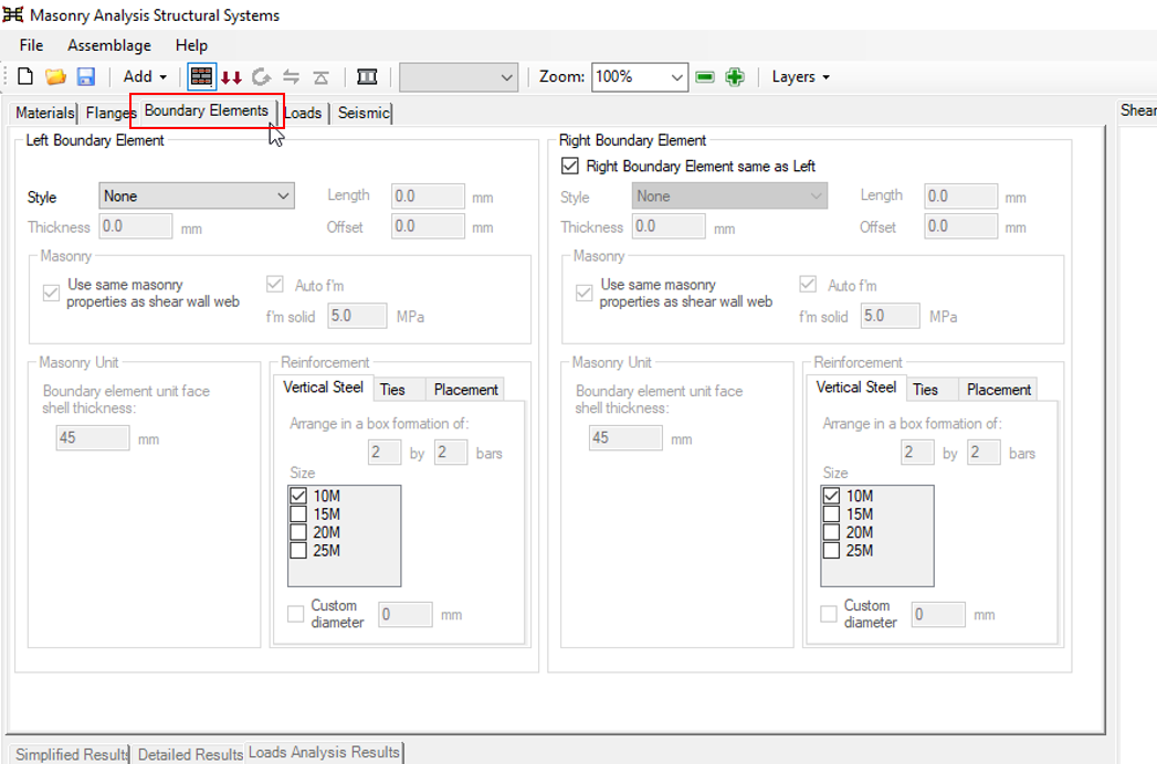
For a shear wall design that does not include boundary elements, the “Boundary Elements” tab can be ignored. Adding boundary elements to a shear wall that already has flanges present will automatically disable the flange option.
Selecting a Style
The default selection for “Style” is set to “None” where boundary elements are not present and the web of the shear wall is solely resisting the entire force. A boundary element can be added to the left side of the shear wall by clicking on the drop-down menu and clicking “”Boundary Element Unit”.
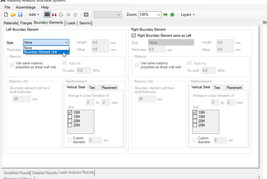
When a boundary element style has been selected, the drawing will update to show the shear wall with default boundary element units on each side.
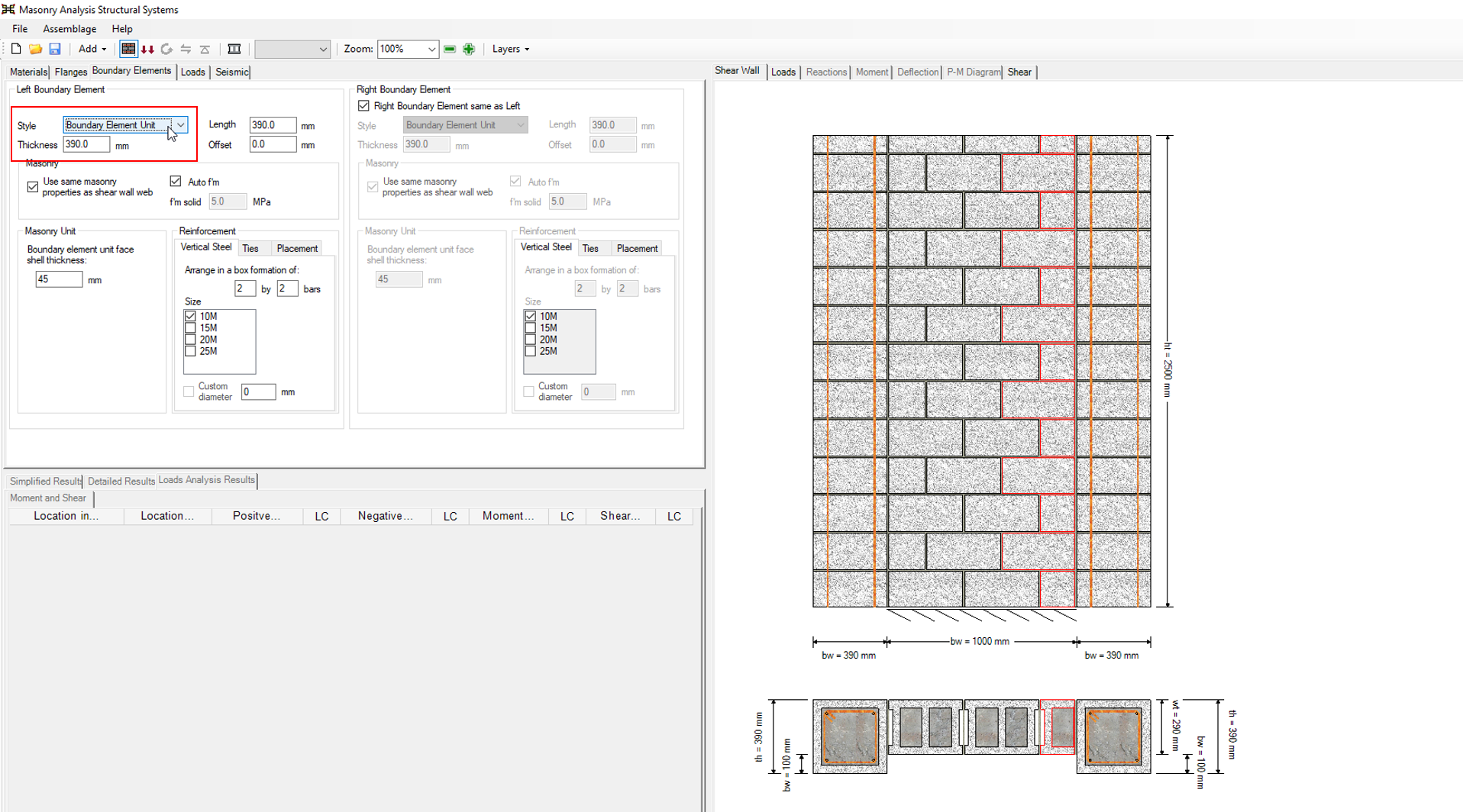
Note that there is an option that is selected or enabled by default for the right boundary element to be same as the one on the left, pictured below:
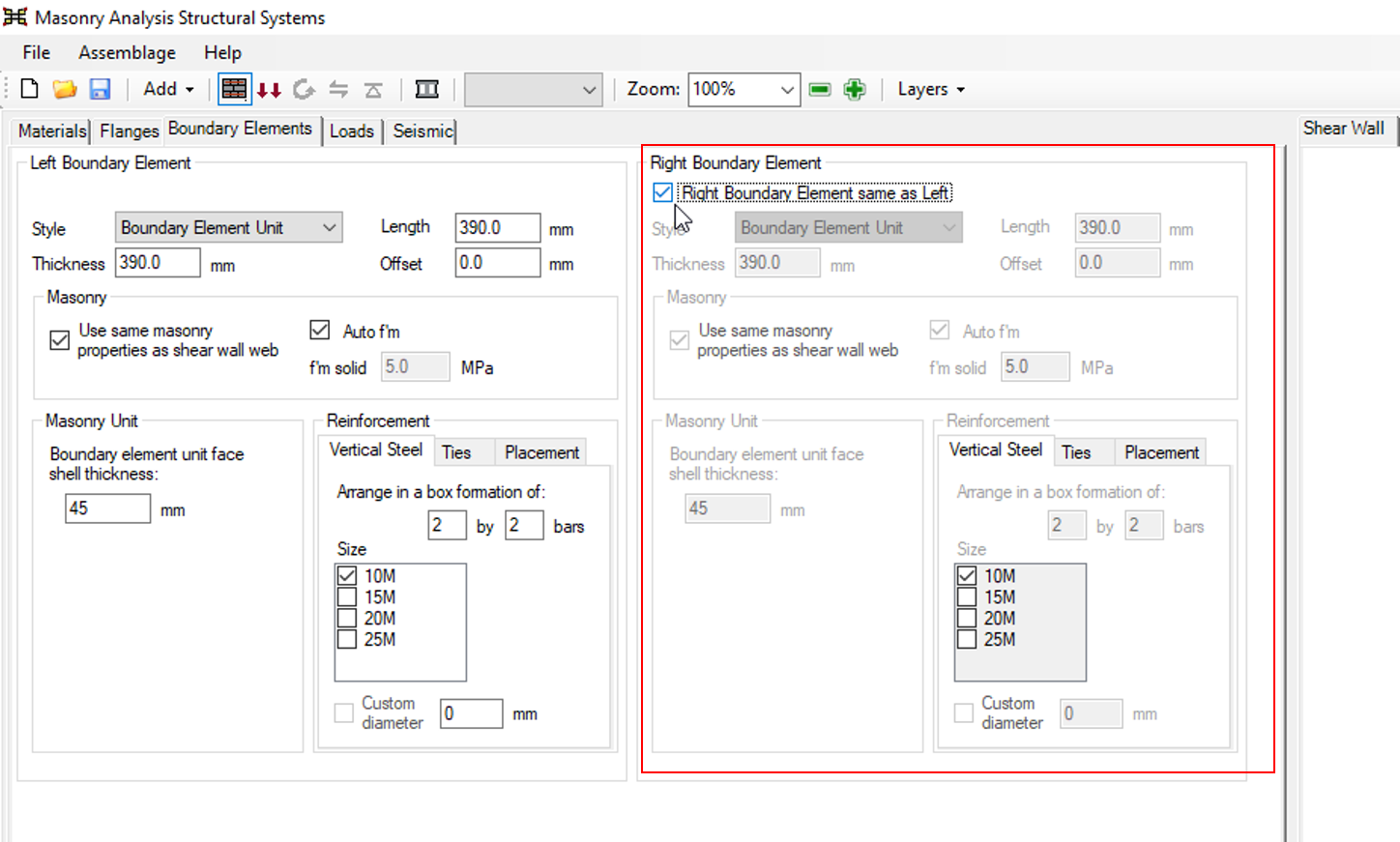
By adding a left boundary element with this selection enabled, an identical right boundary element will be created and added to the shear wall. The selection can be disabled to design a shear wall with only one boundary element, or use boundary elements of different sizes with different properties. If the shear wall design is symmetric, it is easiest to leave this selection enabled so that each input does not need to be entered a second time.
Dimensions
Once a boundary element is added to a shear wall design, MASS starts with default values that can be adjusted by the user. They are defined based on three parameters listed below.
Length
Measured along the shear wall in the same direction as the shear wall length in the materials tab used to specify the length of the web. The initial default value of 390mm can be adjusted as desired and represents the actual length of the boundary element unit being used (as opposed to specifying a nominal length which includes an additional mortar joint).
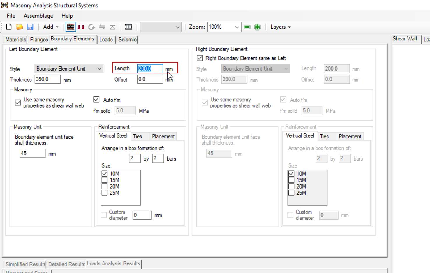
The smallest length that the software will accept is 200mm, the length of one masonry unit cell.
Thickness
Boundary element thickness is measured perpendicular to the length, in the out-of-plane direction. This is the same direction as shear wall web thickness and flange length is measured. The default value of 390mm can be adjusted as desired based on the actual dimensions of the boundary element being used (as opposed to specifying a nominal thickness which includes an additional mortar joint).
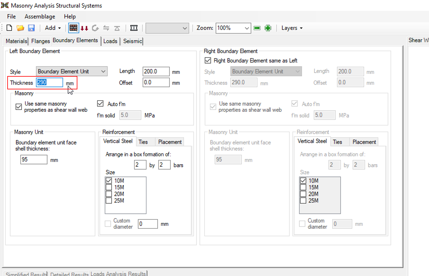
The minimum thickness is set to 290mm, ensuring that that the default masonry units used in the web are not thicker than the boundary elements on each end.
Note: There is no maximum size of boundary element that MASS will prevent the user from exceeding. Very large boundary elements are difficult to use in practical design when accommodating transverse shear at the intersection between the boundary element and the wall (which is outside the scope of MASS and must be designed manually). Other restrictions can include how much the maximum ultimate compressive strain is increased.
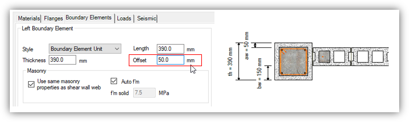
Offset
Offset refers to the space between the outer face of the boundary element and the outer face of the shear wall web, measured in the out-of-plane direction.
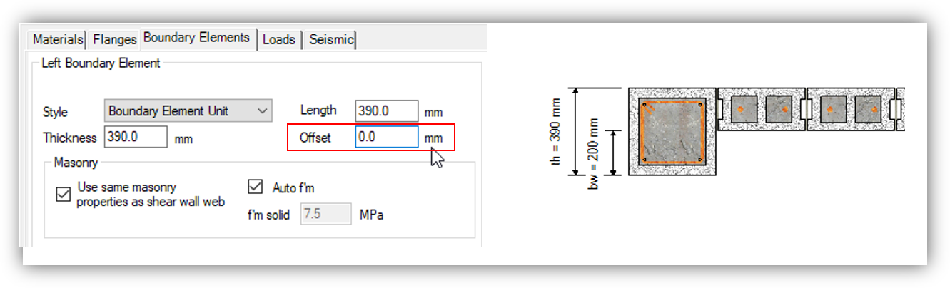 The default value of zero means that the boundary element is placed flush with the shear wall web. The offset can be increased up to the value resulting in the inner face of the boundary element lying flush to inner face of the web.
 Masonry Unit Strength
Since boundary elements are always filled with grout, there is no need to distinguish between multiple f’m values as is done for the web and flanges. f’m,grouted is used for all boundary elements and by default, this value will match f’m,grouted in the shear wall web. This can be changed by un-checking (deselecting) the “Use same masonry properties as shear wall web” check box.
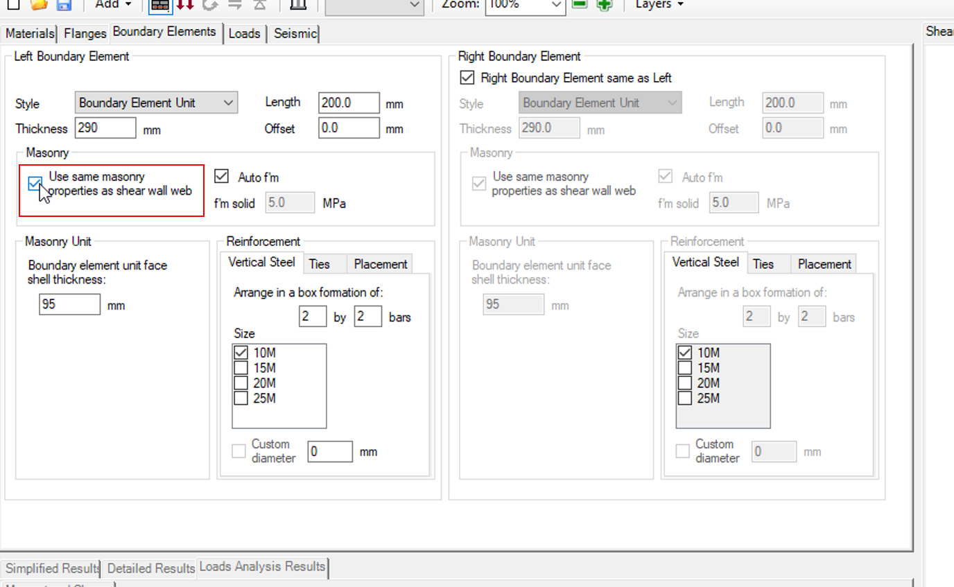 When that option has been un-checked, the user must then enter in the assemblage strength, f’m,grouted, that corresponds to the assemblage strength of the boundary element.
Unit Face Shell Thickness
The material thickness of the boundary element unit wrapping around the confined bars can be specified using the “Boundary element unit face shell thickness:” input field.
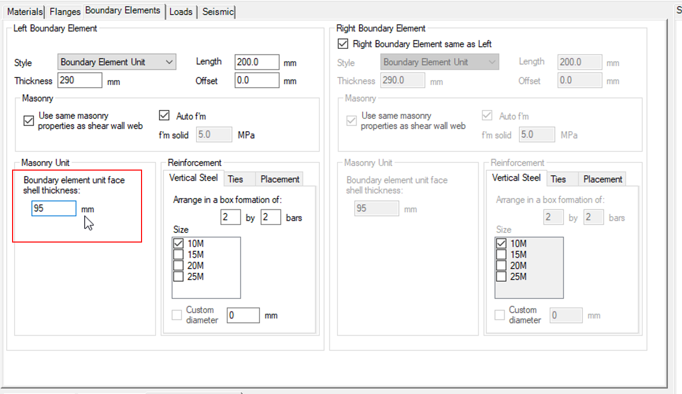 By default, 45mm is used but this must be verified with the manufacturer before specifying it in design. Since the only assemblage strength used is f’m,grouted, the only effect of changing this value is to ensure that there is adequate clear space within the unit between the inside of the face shell and the outside edge of the ties or vertical bars.
Changes made to this input field are immediately reflected in the drawing window.
Reinforcement
Once the overall geometry and properties have been specified for a boundary element, the reinforcement can then be placed for design. The different types of reinforcement explained in the subsections below include vertical or longitudinal bars, ties used to confine the vertical steel in compression, and seismic cross ties which confine the bars not placed at the four corners.
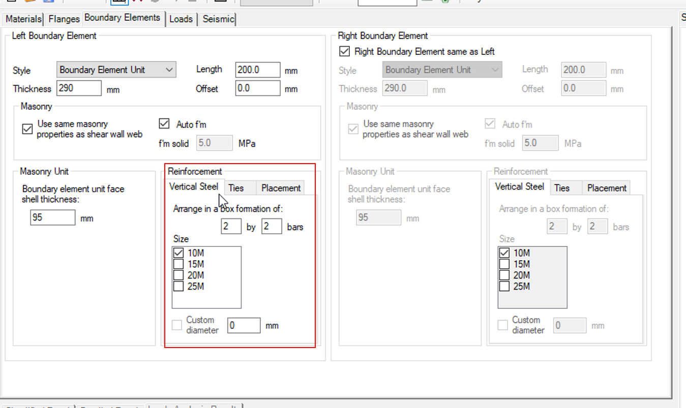
Vertical Bars
Vertical bar (or longitudinal bars measured along the height of a boundary element) are specified in the “Vertical Steel” tab, within the “Reinforcement” section of the boundary element input window.
 With the vertical steel tab selected, the formation or bars and size of each bar can be specified. The two input fields after the label: “Arrange in a box formation of:” ____ by ____ bars is where the user can change the number of vertical reinforcing bars placed within a boundary element.
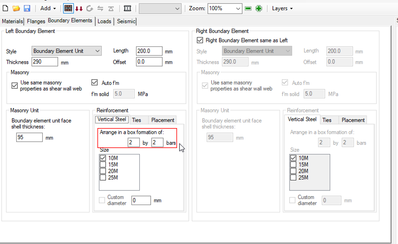 The first entry represents the number of bars places along the in-plane direction of the shear wall and the second represents the number of bars placed along the out-of-plane direction.
The minimum number of bars in each direction is limited to two, ensuring that a box formation is always formed with steel that can be confined from buckling in compression. These numbers can be increased without any hard software limit, however with too many bars, it becomes difficult to also satisfy side cover, interior clearance, and bar separation requirements.
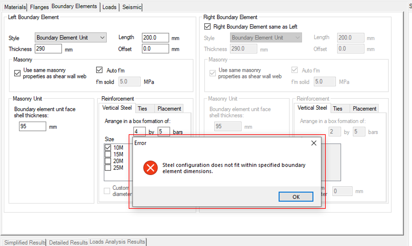 Once the four corner bars are placed, the remaining bars (if applicable) are then spread evenly between the corners. In order to perform a successful shear wall design with boundary elements, the bar configuration must satisfy all spacing and clearance requirements.
The size of vertical bar can be specified in the area below where the layout has been specified.
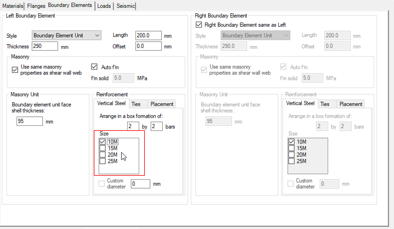 In contrast to the main materials tab where multiple sizes can be selected where MASS cycles through them in the design process, only one size can be placed and that specifies the steel configuration for all loops within the shear wall design process.
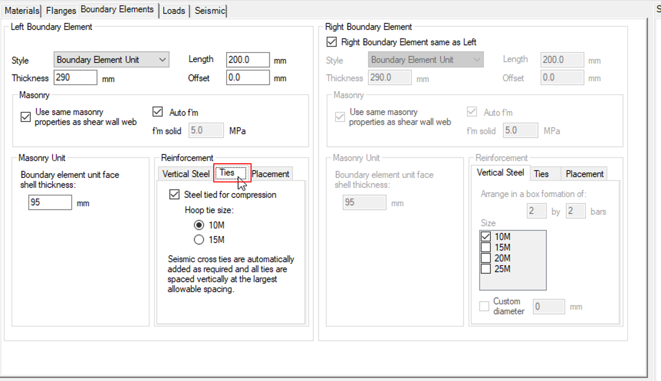
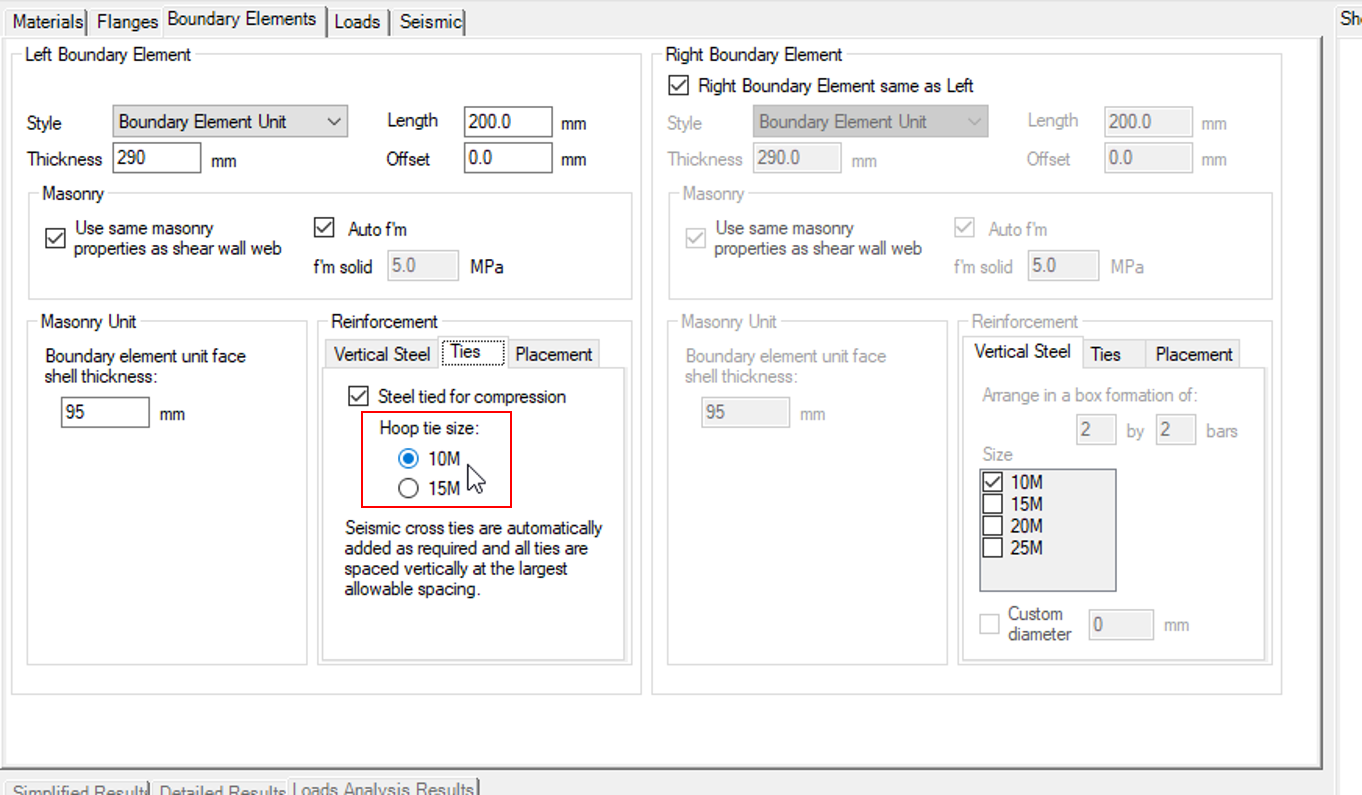
Ties
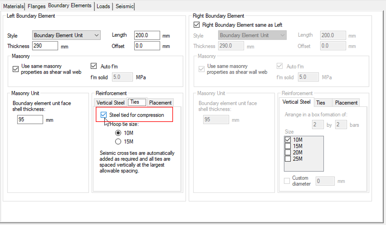
The second available tab in the boundary element reinforcement section is for specifying the placement of “Ties”. This is where ties can be specified to ensure that the vertical bars are tied for compression, similar to what can be done using stirrups in a masonry beam design.
 The default selection for MASS is to tie steel in compression within a boundary element. If this selection is un-checked (disabled), no ties will be placed and the steel will only be accounted for in tension without any placement of ties for confinement. Changes are immediately reflected in the drawing window.
 When ties are present within a boundary element, the size of the tie can be specified using the “Hoop tie size” input area where a No. 10 (default) or No. 15 bar can be used.
 Seismic Cross Ties
For confined vertical bars, there are CSA Standard requirements on how far away a bar can be placed from another confined bar to also be considered laterally supported. MASS performs this check when the ties are placed before design, adding seismic cross ties as needed, shown below:
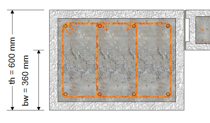
Cross ties are added in both directions as required in such a way that no bar is further than 150mm (CSA S304-14: 12.2.6) from another laterally supported bar. Corner bars are considered confined and laterally supported.
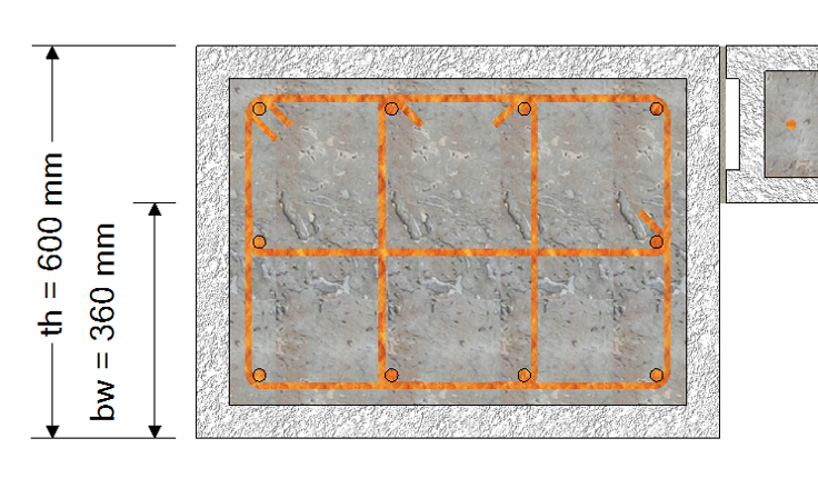 Note: Detailing is not handled by the software an must be prescribed by the designer at their own professional engineering judgement. In some cases, the 135 degree hooks for cross ties must be placed at alternating ends which is not shown by MASS.
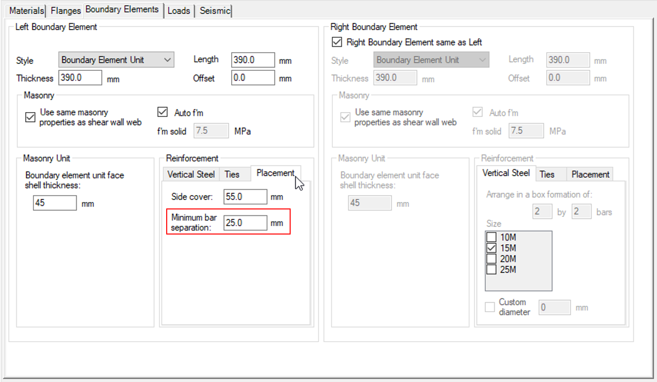
Placement
Reinforcement placement throughout the MASS software has been typically handled within the Minimum Clearances box in the main Materials tab of the input window. A second “Side cover” and Minimum bar separation” field was added for each boundary element for cases when using one value for all reinforcement lead to conflicts within a design.
For example: a shear wall with a 20cm unit used for the web and a vertical No. 25 bar results in a side cover of (190mm – 25.2mm)/2 = 82.4mm of side cover. If a user was performing a design with a particularly large or thick boundary element unit, they may require a larger side cover be specified to place longitudinal bars at an acceptable distance away from the interior face of the boundary element unit face shell in order to design a shear wall that meets detailing requirements by their own calculations outside of the software.
The minimum clearances specified for boundary elements can be located under the “Placement” tab within the “reinforcement” section of the boundary elements input window.
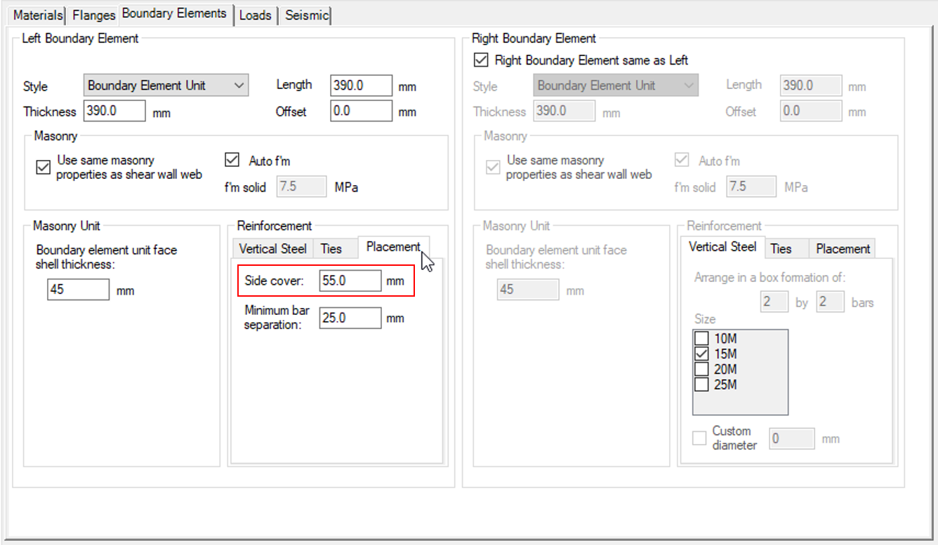 The positioning of boundary element reinforcement can be adjusted by altering these values with the bars placed according to the diagram below:
 MASS places rebar by starting with the corner four bars. If these vertical bars are tied for compression, the outermost edges of the ties are placed at the specified side cover distance away with the longitudinal bars placed against the inside edges. Since the remaining bars (if applicable) are placed evenly distributed, their positioning is checked such that the clear distance between them is not less than the specified minimum bar separation.
Was this post helpful?