

Loads Analysis Results for Walls
Loads Analysis Results
MASS uses a finite element analysis to determine the reactions at the supports, and the values of bending moment, shear force, and deflection at any point along the assemblage. The finite element analysis engine contains a load combination generation engine, and is able to perform the analysis on all the load combinations mandated by the 2020 National Building Code of Canada.
The Load Analysis Results tab is activated when loads are placed on the wall (during the loads input design step). It shows information about the factored moment, factored shear, and service load deflection (including slenderness effects) at points of interest along the height of the wall. The Load Analysis Results tab contain two tabs:
- Moment and Shear
- Deflection
Moment and Shear
To view the factored moment and factored shear data:
- Click on the Loads Analysis Results tab
- Click on the Moment and Shear tab
The Moment and Shear tab contains a table with the factored moment and factored shear (out-of-plane shear and out-of-plane sliding shear) at points of interest along the height of the out-of-plane wall. The interval of the points is 100 mm.
Notice that these intervals all divide equally into a modular length. Additional points are included at the following locations:
- At point load locations
- At the start and end of partial line loads
- At the value of maximum and minimum moment, which is determined by the load analysis engine using a finite element method
- At the centre of the wall
A sample loads analysis results table for moment and shear is shown in Figure 4‑69: Loads Analysis Results (Moment and Shear).
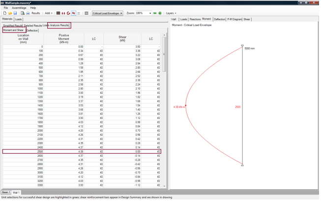
Figure 4‑69: Loads Analysis Results (Moment and Shear)
The first column of the table indicate the location of the points of interest on the height of the wall, from top to bottom.
When critical load envelope is selected, from the Critical Load Envelope drop-down, the value displayed is the largest of moment or shear values for all load combinations; and, the ‘LC’ column shows the number of the load combination for that particular moment or shear value. If a particular load combination is selected (i.e.: LC#2: 1.25D + 1.5L), the columns show the moment or shear values at the location of the points of interest for that particular load combination; and, the ‘LC’ column shows the number of the load combination selected.
![]() Note: Changing the load combination (using the Critical Load Envelope drop-down box) alters the loads analysis results that are displayed. The wall, however, is always designed to resist the critical load combination.
Note: Changing the load combination (using the Critical Load Envelope drop-down box) alters the loads analysis results that are displayed. The wall, however, is always designed to resist the critical load combination.
Notice also, that when the critical load envelope is chosen, the ‘LC’ column under the Loads Analysis Results tab provides users with the load number of the critical load combination.
Continue Reading: Wall Design Strategy
Was this post helpful?