

Wall Design Strategy
Out-of-Plane Wall Design Strategy
Contents
This section provides users with details on how MASS obtains an out-of-plane wall design. Specifically, this section discusses the design philosophy employed in the moment and deflection design step, as well as the shear design step. This information allows the designer to manipulate the out-of-plane wall module with ease.
Moment and Deflection Design Strategy
During the moment design step the magnified factored moment (includes slenderness effects), Mf,Total, is compared with the moment resistance, Mr. In order achieve a successful design Mr≥Mf,Total . To meet this requirement the program performs the design by iterating through the bar size, number of bars per cell, bar spacing, block strength, and block size, in that order. This is summarized in Figure 4‑70: Moment and Deflection Design Hierarchy for Out-of-Plane Wall Module‑. At each iteration, the magnified factored moment is compared with the moment resistance.
![]() Note: MASS can only iterate through the properties that are checked-on. Hence, de-selecting all masonry properties and reinforcement configurations, except for one of each type, converts the program into an analysis tool, rather than a design tool. The program simply determines the moment resistance,
Note: MASS can only iterate through the properties that are checked-on. Hence, de-selecting all masonry properties and reinforcement configurations, except for one of each type, converts the program into an analysis tool, rather than a design tool. The program simply determines the moment resistance,
Mr, and compare that value to the magnified factored moment,
Mf,Total.

Figure 4‑70: Moment and Deflection Design Hierarchy for Out-of-Plane Wall Module
The program begins by iterating up through the selected bar sizes, while fixing: the number of bars per cell, the bar spacing, the block strength and the block size. For the initial configuration, the program uses the smallest block size and the weakest block selected by users. If the masonry unit properties are left unchanged by users, the smallest block size, by default, is a 10 cm unit, and the weakest block strength, by default, is 15 MPa. The least number of bars per cell, by default, is zero. In this case, the wall is unreinforced, and thus the bar spacing, and bar size is not a consideration. If this configuration does not yield a successful moment design, the program attempts the design with one bar per cell, the largest bar spacing, and the smallest bar size. If the vertical steel properties remain unchanged by users, the largest bar spacing, by default, is 2400 mm, and the smallest bar size, by default, is a No. 10 bar.
![]() Note: The transition from zero bars per cell (resulting in an unreinforced wall) to one or two bars per cell (resulting in a reinforced wall) appears to occur seamlessly. This transition however, has some important design consequences; unreinforced walls are designed in accordance to Clause 7 of CSA S304-14 and reinforced walls are designed in accordance to Clause 10 of CSA S304-14.
Note: The transition from zero bars per cell (resulting in an unreinforced wall) to one or two bars per cell (resulting in a reinforced wall) appears to occur seamlessly. This transition however, has some important design consequences; unreinforced walls are designed in accordance to Clause 7 of CSA S304-14 and reinforced walls are designed in accordance to Clause 10 of CSA S304-14.
If a successful design is not achieved with the largest bar size selected, the program iterates up to the next number of bars per cell, and begins reiterating through the bar size possibilities again, while fixing: the bar spacing, the block strength and the block size. If a successful design is not achieved with the largest number of bars per cell permitted, the program iterates down to the next largest bar spacing, and begins reiterating through the number of bars per cell, and the bar size possibilities, while fixing: the block strength and the block size. If a successful design is not achieved with the smallest bar spacing permitted, the program iterates up to the next weakest block strength, and begins reiterating through the bar spacing, the number of bars per cell, and the bar size possibilities, while fixing: the block size. If a successful design is not achieved with the strongest block size permitted, the program iterates up to the next smallest block size, and begins reiterating through the bar spacing, the number of bars per cell, and the bar size possibilities, while fixing: the block size. This iteration procedure continues until a successful design is reached, or all block sizes are exhausted.
![]() Note: Due to the large number of iterations the program performs, it may take up to several minutes to reach a successful design. If the program requires more than several seconds to reach a solution, the smaller weaker blocks, or larger spacing and smaller bar sizes do not provide enough capacity. In this case, users can easily de-select some of the early iterations in the midst of the design process. This will significantly speed up the program.
Note: Due to the large number of iterations the program performs, it may take up to several minutes to reach a successful design. If the program requires more than several seconds to reach a solution, the smaller weaker blocks, or larger spacing and smaller bar sizes do not provide enough capacity. In this case, users can easily de-select some of the early iterations in the midst of the design process. This will significantly speed up the program.
If a successful design is found, the program proceeds to design for the service load deflection (including slenderness effects) of the out-of-plane wall.
Slenderness Effects (P-Δ Effects)
Unlike in the beam module, the moment and deflection design for walls can be significantly affected by the slenderness effects. Slenderness effects are taken into account by looking at the effect an axial load has on a deformed shape (deflection due to deflection). An example of this is shown in Figure 4‑71: P-Δ Effect due to Uniformly Distributed Load‑.
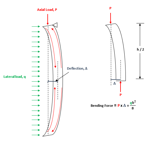
Figure 4‑71: P-Δ Effect due to Uniformly Distributed Load
The applied uniformly distributed load causes the wall to deflect. As a result, one can think of the axial load being applied at a slight eccentricity, acting as a bending force, and resulting in an additional (secondary) deflection.
In MASS slenderness effects are incorporated in moment calculations using the moment magnifier method discussed in the Simplified Results section. In MASS, slenderness effects are incorporated in the deflection calculations using the P-Δ method.
The program begins by loading in the unfactored axial loads, and the unfactored moments for each load combination, the primary deflections, and assumed stiffness value from the load analysis routine. The inputs and properties used in the successful moment design are also used to determine service deflections.
The first step in determining the deflection is determining the deflective shape. The original deflective shape comes from finite element analysis. The secondary deflective shape can be modelled by using a simplified equation that provides a reasonable estimate of secondary effects. Commonly, this simplified shape is derived form the secondary deflection shape for a simply supported wall, experiencing a UDL and an axial load.
Alternatively, it is possible to derive, from first principles, the secondary deflection shape for every loading case and every boundary condition case. This however can be difficult time consuming to derive. Currently, the exact secondary deflection shape is determined for a single wall configuration: a wall with a fixed base and a pinned top with axial loads and lateral uniformly distributed loads only.
With the known secondary deflection, the service moment is required. This is determined by using the equation for maximum service load deflection, together with the P-Δ Load Displacement method. With the service moment known, the service load deflection is calculated.
During the deflection design step the service wind load deflection (including slenderness effects),∆s,Total, is calculated using the out-of-plane wall properties that provided a successful moment design. The service wind load deflection is compared with the maximum allowable deflection (governed by CSA S304-14: 10.14.3), as well as any additional deflection limit users wish to set (on the total deflection). In most cases a successful moment design also produces a successful deflection design. If the design fails in deflection, the program returns to the moment design iteration procedure. In out-of-plane walls, the vertical reinforcement provides the additional cracking stiffness to minimise deflection due to lateral loads, eccentricity of axial loads, and slenderness effects (i.e. deflection caused by deflection).
Shear Design Strategy
If the moment and deflection design step is successful, the program can proceed to the shear design step. During the shear design step the sliding shear resistance, (at each course ), Vri, and the shear resistance, Vr, are calculated using the out-of-plane wall properties that provided a successful moment and deflection design. The sliding shear resistance (at each course) is compared with the factored shear (at each course).
In order achieve a successful shear design;Vri≥Vfi and Vr≥Vf,max. In most cases a successful moment design also produces a successful shear design. For the out-of-plane module only, if the design fails in shear, the program must return to the moment design iteration procedure. This does not happen for beams or shear walls. In the beam module, the program can add stirrups to increase shear capacity, before resorting to increasing the moment capacity of the beam. In the shear wall module, the program can add joint.
Continue Reading: Shear Walls
Was this post helpful?