

Shear Wall Element Deflection
Outlining how exactly MASS is able to check a shear wall element against seismic drift limits
Contents
This section will explain how effective stiffness, linear deflection, and final drift deflection are determined within MASS.
The deflection values defined in this section are for single-storey shear walls. For understanding how MASS deals with multi-storey shear wall deflection, the important differences are outlined in the Multi-Storey Shear Wall Deflection page, linked here.
Overall Deflection Summary
Calculating drift values used for shear wall design is a complicated process made up of many steps. Starting with adding effective bending stiffness used for initial deflections based on linear elastic analysis, MASS is able to check a shear wall against seismic drift limits for a shear wall element. Note that while only the load combinations containing an “Earthquake” type load are checked, linear deflections are still displayed using the loading and effective bending stiffness for all other load combinations.
The final deflection value determined by MASS for a masonry shear wall is equal to the initial deflection multiplied by the overstrength and ductility SFRS modification factors and then divided by the importance factor. The initial deflection is determined using basic structural mechanics using linear elastic behaviour, based on distributed loading as well as an effective stiffness and effective area outlined in CSA S304-14[16.3.3]. This effective stiffness can vary along the height of the wall (if looking at a multi-storey design) and can have a value between the cracked and uncracked shear wall stiffnesses, as a function of axial load. The same applies to the effective area.
Each of the terms described in this process is explained in further detail below:
Starting with the final drift of a shear wall, the following bullet point list lays out the inputs needed as well as links to a description of how MASS determines each one. Links are available to jump to that section for a more detailed explanation.
- Final deflection (Drift Values) (click to jump)
- Overstrength SFRS force modification factor (Seismic Tab page linked here)
- Ductility SFRS force modification factor (Seismic Tab page linked here)
- Importance factor (Shear wall design steps section linked here)
- Initial Deflection (click to jump)
- Lateral Loading (Shear wall load distribution section linked here)
- Effective Bending Stiffness (click to jump)
- Reference Young’s Modulus (click to jump)
- Effective Moment of Inertia (click to jump)
- Axial Loading (click to jump)
- Uncracked Moment of Inertia (click to jump)
- Cracked Moment of Inertia (click to jump)
- Shear Modulus (click to jump)
- Effective Area (click to jump)
- Uncracked Area (click to jump)
- Cracked Area (click to jump)
- Effective Area (click to jump)
Effective Bending Stiffness
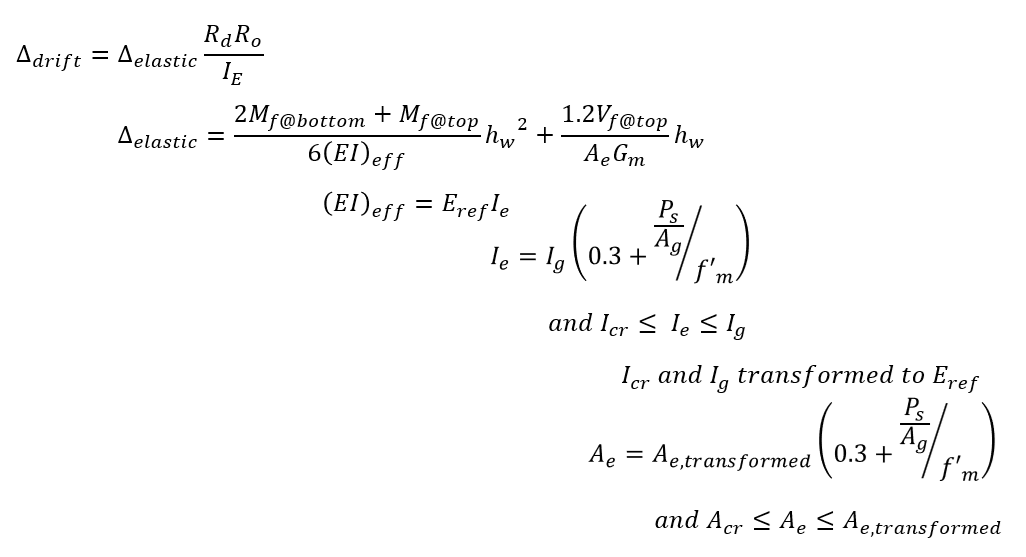
Bending stiffness, or (EI)eff, can be a complicated calculation for a shear wall. It can be simplified by multiplying the reference stiffness used for the transformed cross section by the effective moment of inertia.
![]()
This (EI)eff term takes many cross-section aspects into account, as well as any possible stiffening effects due to applied axial loads.
Reference Modulus of Elasticity
In order for MASS to consider the differences in stiffness between hollow masonry, grouted masonry, and reinforcement, a modular ratio (ratio of one material stiffness to another) can be used to relate the behaviour of a cross section containing multiple materials to an equivalent cross section analyzed as if it were constructed using one material.
These modular ratios are calculated for each material by dividing its modulus of elasticity to that of the reference material. This can be done with any material or even some other stiffness selected as the reference stiffness and as long as they are used correctly and consistently throughout the process, the resulting masonry movement will work out to the same solution.
MASS uses the least stiff material to treat as the reference material in order for all of the modular ratio values to be greater than one. This results in all other materials to always be scaled up in relative size within the cross section.
CSA S304-14: 6.5 (shown below) outlines the values used by MASS for the various materials within a masonry shear wall:
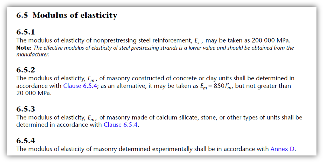
Note that since the modulus of elasticity is directly correlated to compressive strength, the least stiff material is also the weakest.
Effective Moment of Inertia
When a shear wall is loaded to ultimate failure, its behaviour changes once damage starts to occur, the masonry cracks, and reinforcement is engaged and yielding in tension. It is a complicated relationship but a basic approximation of the stiffness transitioning from uncracked to cracked plus stiffening effects of applied axial load is available in CSA S304:16.3.3:
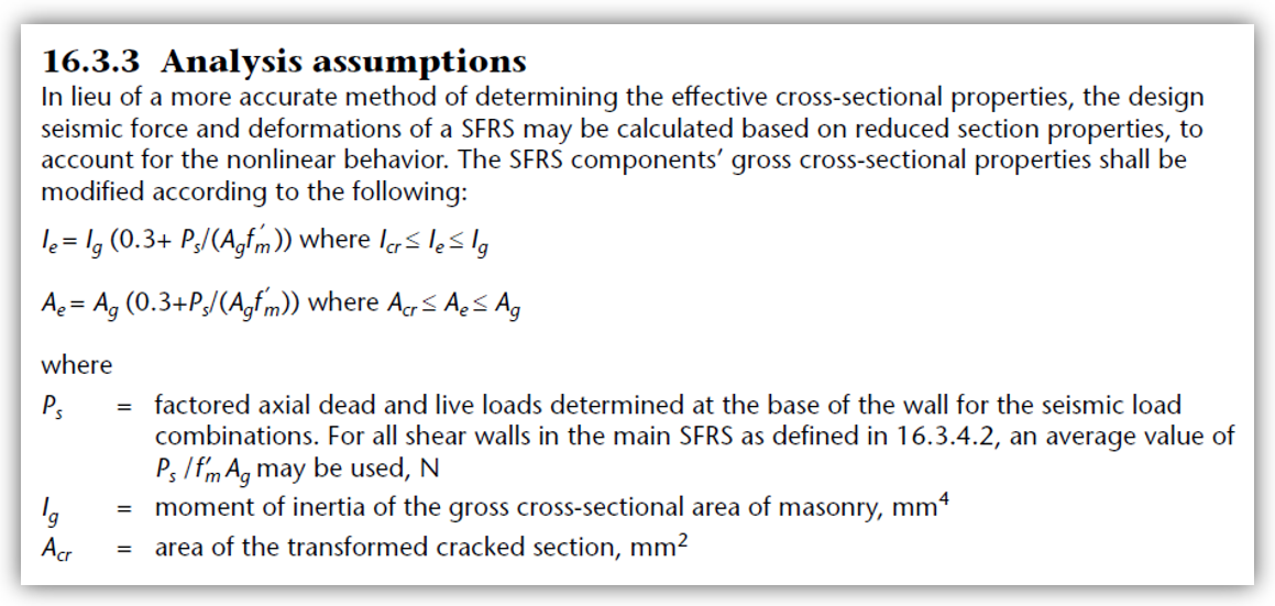
This clause provides a method for using an approximate effective stiffness for the deflection calculation methods that are based on linear elastic analysis and mechanics. The three components of this effective stiffness value can be broken down into axial stress, uncracked stiffness, and cracked stiffness.
Axial Stress
To account for possible stiffening effects from axial load applied to a shear wall, axial stress is approximated by clause 16.3.3 as well as MASS as the total factored axial load divided by gross cross sectional area, Ag. The ratio of this stress to the compressive strength of masonry, f’m, may affect to what degree the shear wall is stiffened by the applied axial load.
Note: In chapter 16 of CSA S304: Design of Masonry Structures, Ps refers to the factored axial load under a seismic load combination, not to be confused with a service load.
When the factored axial load divided by Ag reaches 70% or 0.7 of f’m, the effective moment if inertia is capped at the uncracked value. (Source: math)
Uncracked Moment of Inertia
The uncracked or gross moment of inertia for a masonry shear wall is calculated by MASS using a transformed cross section to account for different material stiffnesses within the wall. All masonry (hollow and grouted) as well as vertical reinforcement is included in this calculation.
The uncracked moment of inertia is the highest possible value for the effective moment of inertia allowed by CSA S304: 16.3.3, explained above (click to jump).
Cracked Moment of Inertia
Using a transformed cross section that only includes reinforcement in tension coupling with masonry under compression and reinforcement in compression about a location where the total first moments of area balances to zero, a moment of inertia can be calculated.
The cracked moment of inertia effectively serves as the lowest possible value for the effective moment of inertia.
Flanges and Boundary Elements
When a shear wall cross section contains flanges or boundary elements, the moment of inertia is determined separately for each additional element, taken relative to the transformed center of mass. These additional terms are added to the web’s transformed moment of inertia with no further modification required because the same reference point was used for each using the parallel axis theorem.
Once the effective moment of inertia is used to calculate (EI)eff, the entire cross section has been taken into account and all that remains in calculating the deflection using linear elastic analysis is the loading pattern on the shear wall.
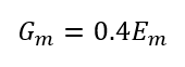
Shear Modulus
Shear Modulus, or Gm, is a fairly straight forward calculation for a shear wall. It can be related to the reference Modulus of Elasticity, Em, as:
Effective Area
When a shear wall is loaded to ultimate failure, its behaviour changes once damage starts to occur, the masonry cracks, and reinforcement is engaged and yielding in tension. It is a complicated relationship but a basic approximation of the area transitioning from uncracked to cracked plus stiffening effects of applied axial load is available in CSA S304:16.3.3:
This clause provides a method for using an approximate effective area for the deflection calculation methods that are based on linear elastic analysis and mechanics. The three components of this effective area value can be broken down into axial stress, uncracked area, and cracked area.
Uncracked Area
The uncracked or gross area for a masonry shear wall is calculated by MASS using a transformed cross section to account for different material stiffnesses within the wall. All masonry (hollow and grouted) as well as vertical reinforcement is included in this calculation.
The uncracked area is the highest possible value for the effective area allowed by CSA S304: 16.3.3, explained above (click to jump).
Cracked Area
The area of the transformed cracked section. The cracked area effectively serves as the lowest possible value for the effective area.
Lateral Loading
Since there can be any combination of axial point loads, lateral point loads, and applied moments at the top of the wall, the following deflection equations were derived and used within MASS to calculate shear wall deflection. Through then use of linear elastic mechanics, all of the equations were structured to be in terms of both the moment at the top of the wall and the moment at the base of the wall. This is done for each load combination but recall that only seismic load combinations are checked against drift limits.
Note: Axial load may impact deflection via the increase in bending stiffness but will have no direct impact on the moment profile along the wall. Multi-Storey axial loads applied at eccentricities are converted by MASS to axial loads with an accompanying applied moment where the applied moment component will affect the moment profile.
Linear Elastic Deflection
For an individual shear wall, the deflection is determined as a function of bending stiffness and applied loading, where the loading is expressed in terms of the moment at the top and bottom of the wall. There are multiple ways to calculate and express this deflection where the simplified version is displayed by MASS:
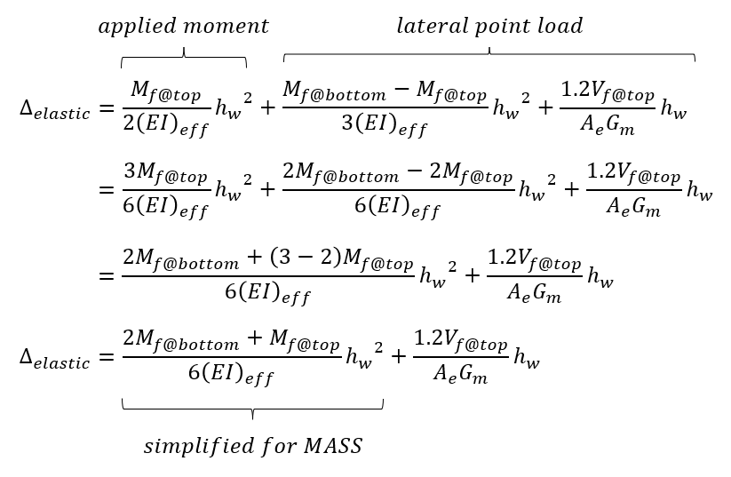
When checking by hand, deflections can be calculated using simplified expressions from both the applied lateral load and moment at the top of the wall, added using the superposition principle to obtain the same results as the software.
Elastic deflections are calculated for each load combination, taking into account the shear and moment profile for each case. Since bending stiffness and area can change as a function of axial load through Ieff and Aeff it must also be calculated for each load combination.
Note: For multi-storey shear walls, these deflections will be impacted by the overall displacement at the base of the wall as well as the rotation occurring at the top of the wall beneath if not at the ground floor. More information can be found on the Multi-Storey Shear Wall Deflection page, linked here.
Seismic Drift
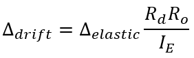
Although some non-linear behaviour has been considered through the use of an effective bending stiffness discussed earlier, the building code requires that deflections used to compare to drift limits be multiplied by the following term, taking into account the over-strength and ductility SFRS force modification factors used to determine the applied loads, as well as the importance category, shown below:
Note: MASS automatically uses this equation to convert linear deflections to seismic drift values. It is important that the user has specified the correct ductility category and importance factor that matches what was used to calculate the unfactored loads, applied to the shear wall.
Over-strength Factor, Ro
The over-strength SFRS force modification factor is specified within the seismic tab and will already have been considered by the user when determining the unfactored loads being applied to the wall. Based on SFRS designation from the NBCC, they can have two possible values for masonry construction:
- Unreinforced shear walls: Ro = 1.0
- Conventional construction, moderately ductile, and ductile reinforced shear walls: Ro = 1.5
It is important that the user review and confirm that the over-strength factor used by MASS matches what was used in hand calculations for determining seismic loads.
Ductility Factor, Rd
The ductility SFRS force modification factor is specified within the seismic tab and will already have been considered by the user when determining the unfactored loads being applied to the wall. Based on SFRS designation from the NBCC, they can have four possible values for masonry construction:
- Unreinforced shear walls: Rd = 1.0
- Conventional construction shear walls: Rd = 1.5
- Moderately ductile shear walls: Rd = 2.0
- Ductile shear walls: Rd = 3.0
It is important that the user review and confirm that the over-strength factor used by MASS matches what was used in hand calculations for determining seismic loads.
Importance Category, Ie
The importance category, used to convert linear elastic deflections to drift to compare to maximum inter-storey drift limits, can be found and specified in the loads tab. Click here to be taken to the importance factor section within the shear wall design steps page.
Shear Wall Drift Example
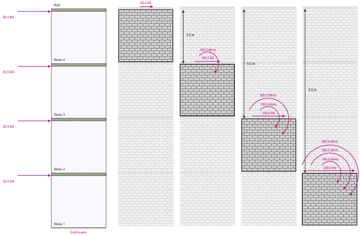
A drift value will be calculated for the example wall shown below. Only one load combination is shown by hand (1.0D + 1.0E) but the software follows the same process, repeated as many times as needed to check each possible load case.
Consider the bottom storey within a conventional construction, four storey shear wall with seismic loads applied and cross section as shown:
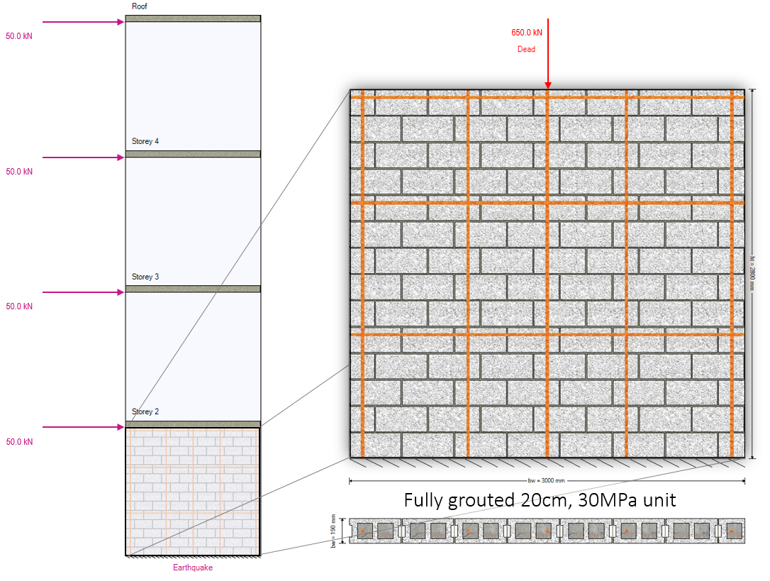
Note that to recreate this in MASS, create a 4 storey shear wall with a length of 3m and a total height of 12m. Using the default equally spaced floor locations, apply a lateral point load of 50kN at each floor and axial dead loads of 110kN at the roof and 180kN at all other floors.
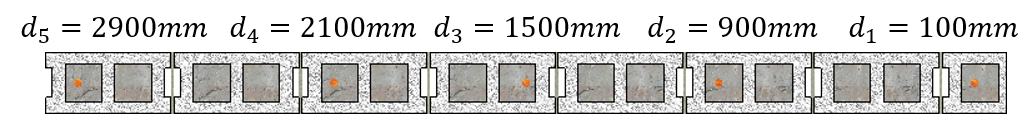
The cross section is fully grouted, constructed using a 20cm H/30/A/O masonry unit. Vertical 25M bars are placed at no further than 800mm apart shown above and the total dead load acting on the shear wall from all floors and walls above is 650kN (including self-weight from the masonry above). Starting with determining the effective bending stiffness of the cross section, the bar positions are shown below:
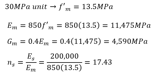
The masonry unit can be used to determine the specified assemblage compressive strength. From that information, Young’s modulus can be calculated which is needed to determine the modular ratio which takes varying material stiffnesses into account. The Young’s modulus is also needed to determine the Shear modulus.
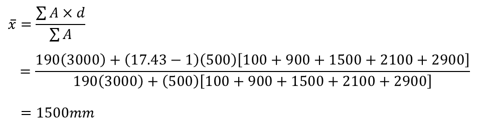
For calculating the uncracked moment of inertia, the centre of mass is needed to know about which location the stiffness be taken. Seeing as the example wall is symmetric, the centre of mass is the horizontal middle of the wall (L/2) but the calculation is shown below to verify.
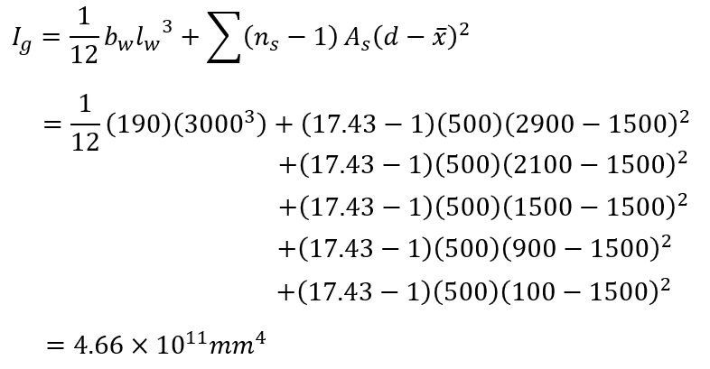
The gross cross section moment of inertia is then calculated:
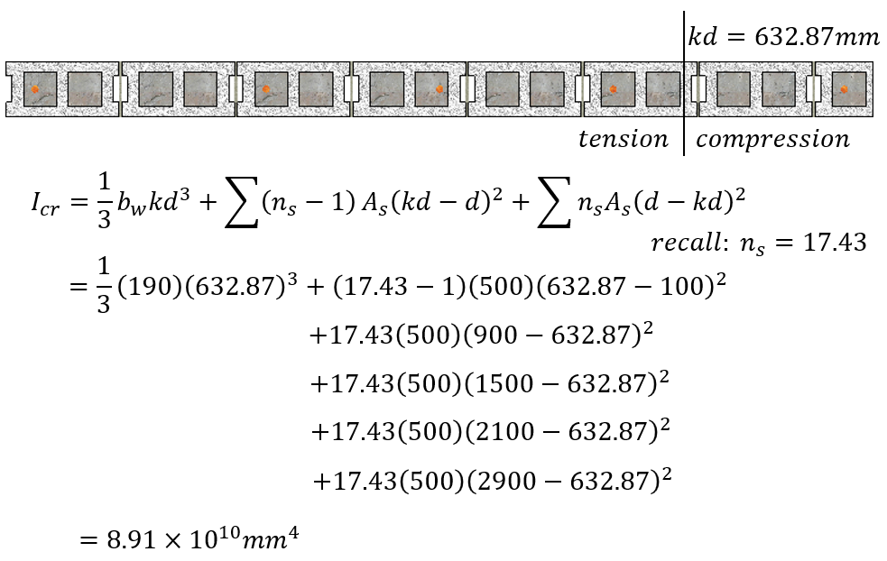
The total axial seismic load is needed to calculate the effective stiffness, as well as the cracked moment of inertia which serves as a lower bound to compare against. Starting with the cracked moment of inertia, the location about which the first moment’s of area between compression and tension are balanced can be solved for and is determined by MASS in this case to be 632.87mm. Based on this crack depth, the moment of inertia taken about this location is calculated below:
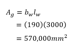
 The gross area can also be calculated:
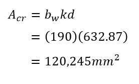
As well as the cracked area of the wall. This is based on the neutral axis of depth for the cracked section determined by MASS to be 632.87mm:
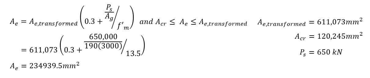
The transformed effective area is determined by expressing the hollow masonry and steel properties as equivalent grouted masonry properties, thereby allowing the section to be analyzed on a consistent basis. MASS calculates this value as: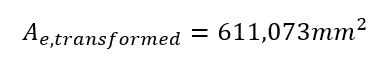
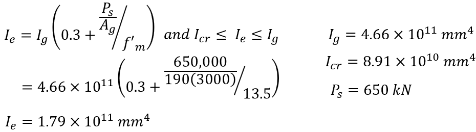
At this point, everything needed to calculate the effective moment of inertia and the effective area is now known and CSA S304-14: 16.3.3 can be used:
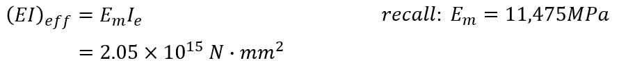
From here, the total effective bending stiffness is calculated and ready to use for deflection calculations:
To calculate the linear elastic deflection, the moment profile along the height of the shear wall is required. This can be determined in the process that is outlined in further detail on the multi-storey shear wall load distribution page.
The resulting moment profile is 900kN*m at the top of the wall and 1460kN*m at the base.
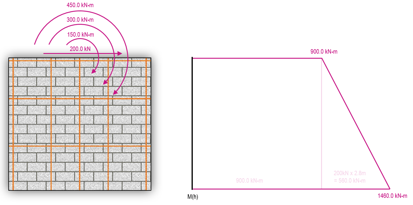
These can be input directly into the deflection equation used by MASS to calculate the shear wall deflection based on linear elastic behaviour:
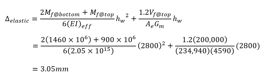
To go from this deflection to a usable drift value to check against drift limits, the linear elastic deflection must be multiplied by the product of Rd and Ro, divided by the factor attributed to the Importance category:
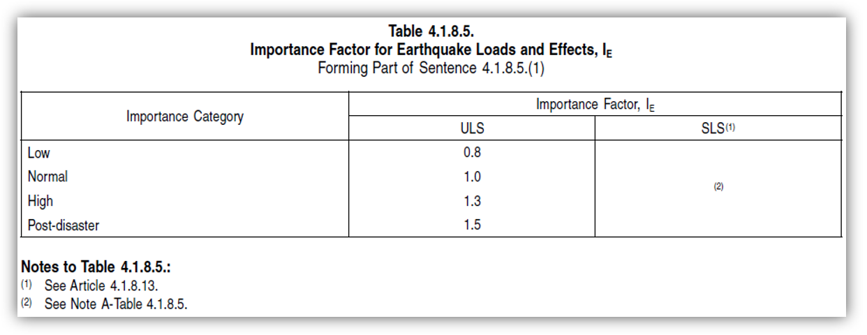
In this example, the importance category is Normal so the Factor used for IE is 1.0.
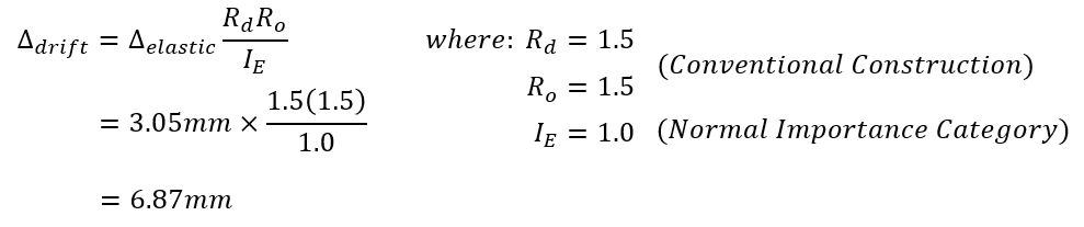
And there you have it! The total drift at the top of storey 1 in the example shear wall will be 6.87mm. This can be compared to the limits outlined in NBCC 2015: 4.1.8.13(2):
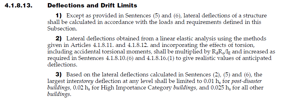
For a Normal importance category structure, the maximum allowable drift for the difference between at grade the the top of storey 1 is 0.025 times the storey height. In this case, that limit is 70mm, which the wall is experiencing movement well within.
For more information on the added complexities of determining movement for the stories above, click here to continue reading about multi-storey shear wall deflection.
Continue Reading: Shear Wall Self-Weight