

Multi-Storey Shear Wall Design Steps
Covering the process of creating and designing a Multi-Storey Shear Wall using MASS
The Multi-storey module added to MASS with the release of version 4 adds the ability to coordinate the design of several individual shear wall elements with the added steps of load distribution and coordinating the design of several cross sections which in previous versions needed to be done manually by the user. This page outlines the steps from creating the wall, placing floors, and applying loads, all the way to performing a design and grouping floors with the same properties.
To get started, select the “Create Multi-storey Shear Wall” option from the opening welcome screen or within an existing project file, select “Multi-Storey Shear Wall’ form the “Add’ drop down menu on the main toolbar.
Overall Dimensions and Materials
The main input area of the multi-storey module is the Materials tab, where the assemblage dimensions and material properties are specified.
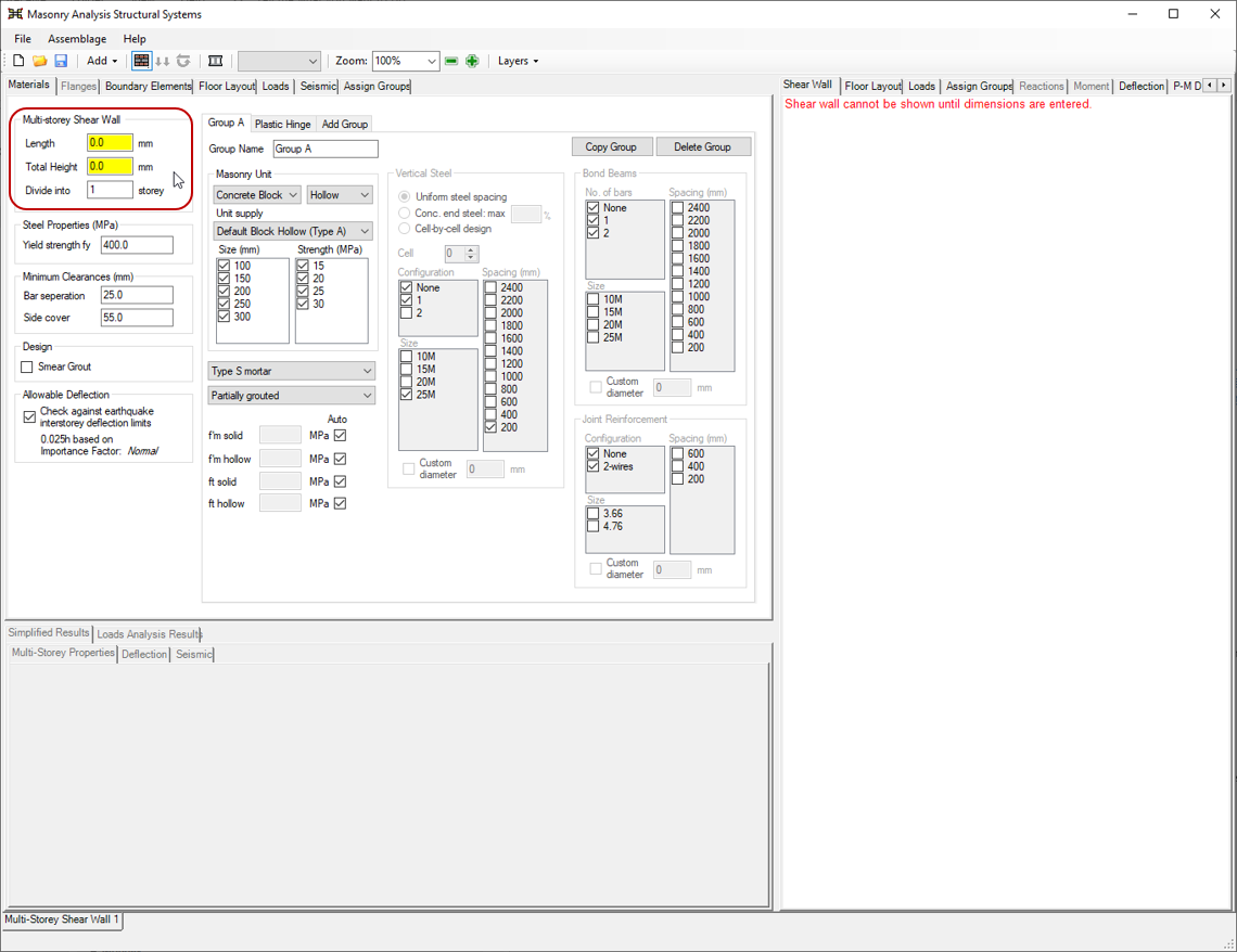
Before anything is shown in the drawing window, the overall, outer dimensions must be specified. All values are entered in mm.
Length
The length must be kept constant along the height of all multi-storey shear walls designed using MASS. It can be specified using the “Length” field in the main materials input tab. It is highlighted in yellow when a new assemblage has been created and no value has been entered yet.
The minimum allowable length for a shear wall is at least one half of the length of a masonry unit. For the standard stretcher concrete block, the nominal length is 400mm (actual length is 390mm) so the shear wall much be at least 200mm in length.
Note: There is no maximum length accepted by the software, however it is up to the discretion of the designer’s critical engineering judgement to determine whether a shear wall should be divided into smaller assemblages with a movement joint.
Total Height
The “Total height” field is the only height related input field within the multi-storey shear wall module. The heights for each individual design are determined by MASS after the floors are specified and placed by the user. When a new assemblage has been created, the total height input field is highlighted in yellow before any value has been entered.
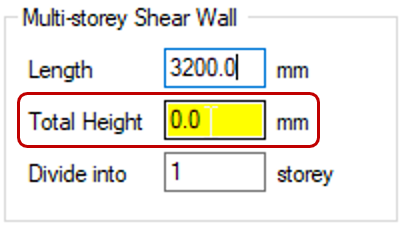
The minimum allowable height that will be accepted by MASS is one full block height plus the thickness of one floor slab or 400mm – which ever height is greatest. There is no maximum allowable height for this field, however MASS does check the shear wall height against some values specified in the National Building Code of Canada.
Dividing into Floors
Once the outer dimensions have been entered and a shear wall is displayed in the drawing window, the wall can be divided into smaller elements using the “Divide into _____ floors” input field. The default value of “1” is pre-populated where the entire height of the multi-storey assemblage is labelled and treated at Storey 1.
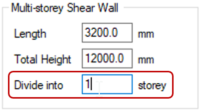
The maximum value accepted by MASS is equal to the number of storeys at which each floor height is equal to one full masonry unit. For example, a 2m shear wall cannot be divided into more than 5 floors because this would result in less than one full block between floors.
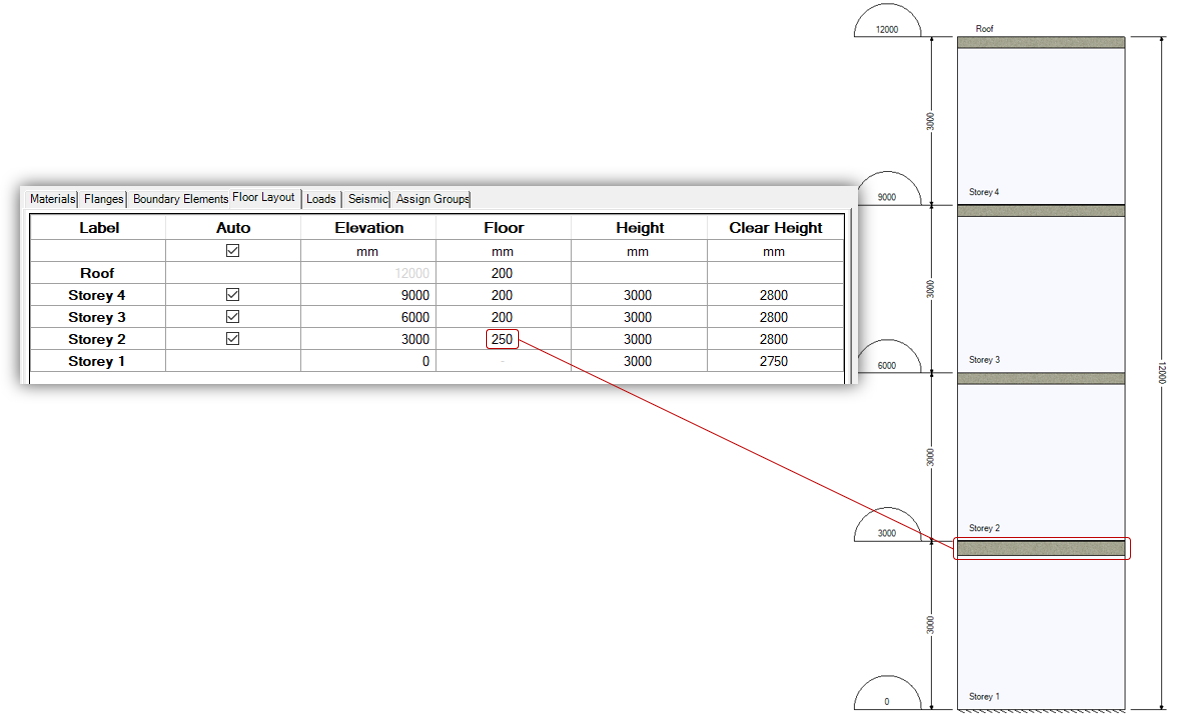
Once a new value has been entered, the shear wall is split up evenly into floors al having the same height. This can be changed later on using the “Floor Layout” tab. If the 12m tall shear wall shown below is divided into 4 storeys, the height of each storey is automatically determined by MASS is 3m or 3000mm each where the floor slab occupies 200mm and the remaining 2800mm is designed as masonry.
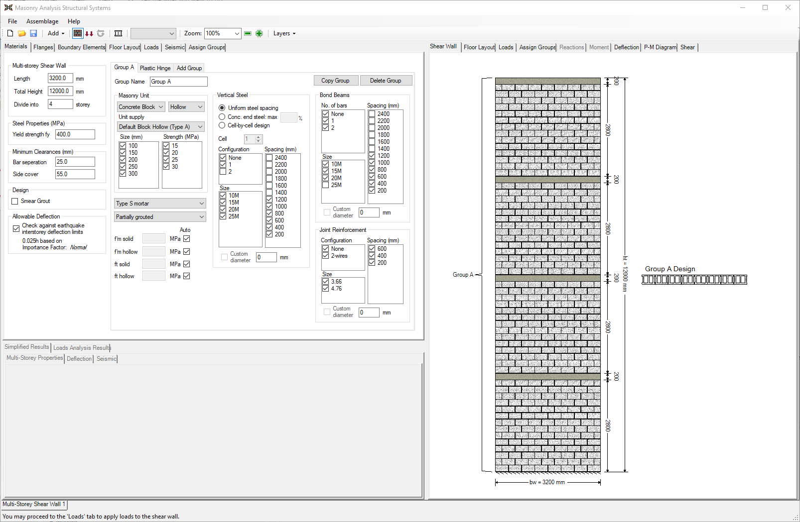
Once a multi-storey shear wall is divided into floors, MASS creates a shear wall element assemblage for the design each storey. There are not visible until a design has been performed and have the same length and total height as the multi-storey shear wall. The actual assemblage height for each element is equal to the clear distance between the top floor surface and bottom surface of the slab above.
Note: A single storey shear wall can still be designed using the multi-storey shear wall module. While all design calculations are dine within the shear wall element module, and in many cases yield identical results, it may be beneficial to use the multi-storey module for cases where the user wishes to use different cross sections along the height of a single storey shear wall. This is commonly done for shear walls requiring the use of a plastic hinge.
Material Property Groups
Since the actual design process is performed by the individual shear wall element tabs, the material properties used are inherited from the main parent multi-storey assemblage tab. While it may be desirable for each floor to have a unique design, it is often the case where multiple floors use the same masonry unit size and strength, as well as grouting and reinforcement layout. This is where grouping material properties can be beneficial.
By default, the entire multi-storey shear wall will share the same cross section design under the “Group A” material properties. As a result, the governing axial stresses, moments, and shear forces at the base of the wall will have an effect on the final design used at the top storey where the loads are not a large.

This can be changed later on using the “Assign Groups” tab which will be covered in further detail in a subsequent section on this page.
Editing Groups
The allowable material properties used for the design of an individual shear wall element are mirrored from the group properties in the multi-storey Materials input tab. By default, these are the same as the initial selections for a shear wall element. Making changes to what is shown under the “Group A” properties will result in those same changes being applied to all elements that are tied to “Group A” – all of them be default.
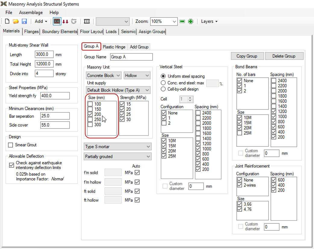
For example, if all unit size selections except for the 200mm thickness are disabled, leaving only the 20cm block option available, all elements designed using that group will use a 20cm unit. Changing properties in the multi-storey properties would have the same effect as designing the same wall using only the shear wall elements and deselecting the same properties for each tab, one by one. This is one of the ways that the multi-story assemblage option saves time for the end user.
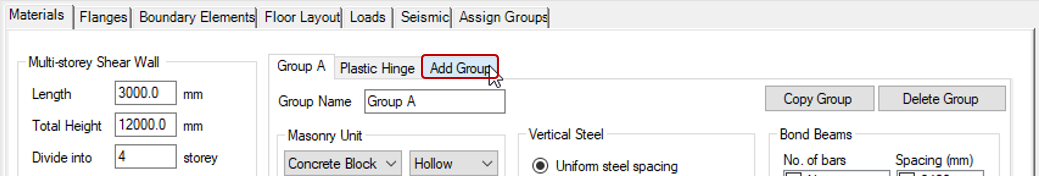
Adding Groups
With the exception of the “plastic hinge” group which is a special case and outlined further below, the only usable group available by default is “Group A” which is used for the entire height of the multi-storey design.
An additional group can be created clicking on the “Add Group” tab, available to the right of the Plastic Hinge group.
Once a new group is added, the group tab will be generated to the left of the Plastic Hinge tab. The default naming convention uses letters but can be modified by the user as desired.
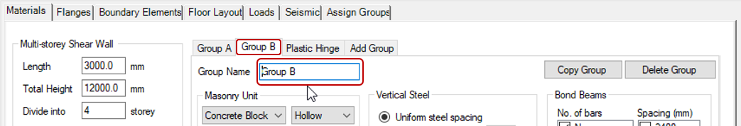
New groups can be modified using the same process outlined above.
Note: Non-default groups will not be used for design until they have been assigned to elements of the multi-storey shear wall design. This is explained further below.
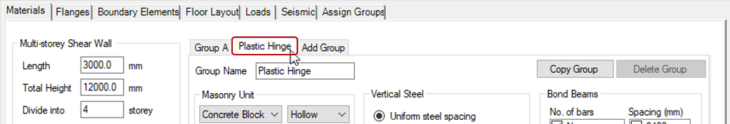
Plastic Hinge Group
The Plastic Hinge Group behaves like any other with the exception that it is used automatically based on the seismic selections input by the user. Selections within this group are used within the plastic hinge region of a design where there are additional code and standards requirements that must be considered within the design.
To view and modify the Plastic Hinge Group, it can be selected in the list of Groups, to the right of Group A by default if no other groups have been added.
In addition to being assigned automatically which is covered in further detail in the Assign Groups tab section of this page, the Plastic Hinge Group cannot be deleted. Designs not containing a plastic hinge region will simply not reference the property selections within this group.
Switching Groups
The material properties shown in the drop-down menus and check boxes correspond to the Group tab that is selected. To view the selections for a different group, select the desired group tab to be viewed or edited. When a different tab is chosen, the selections in each field are automatically updated within the Group property section of the input window.
There is no option to apply changes or save selections for material groups. This is because all changes are automatically saved and applied as they are edited.
Copying Groups
An existing Group and all of the selections can be copied to a new group by clicking on the “Copy Group” button.
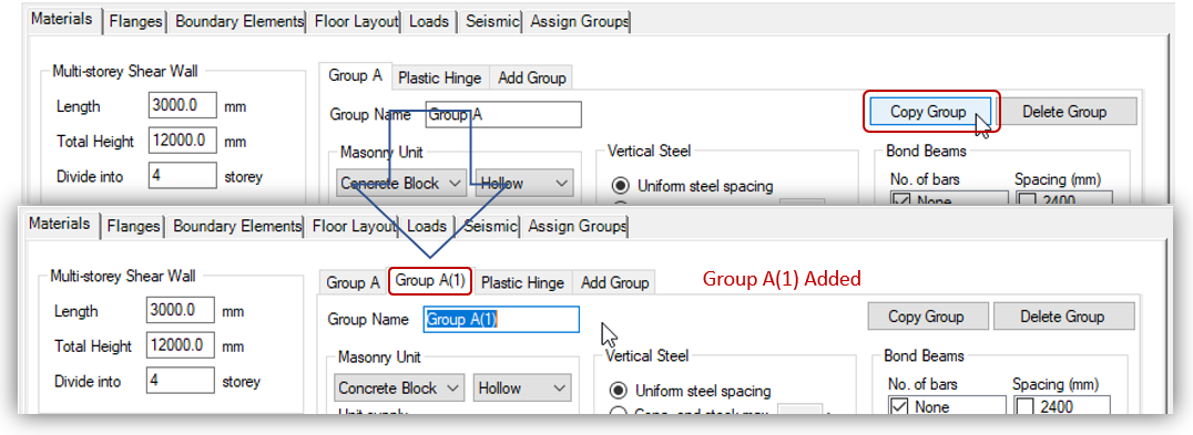
Copied Groups are inserted to the left of the Plastic Hinge group.
Note: A copied Group will not be used unless assigned to part of the shear wall design using the Assign Groups input tab, covered further down this page.
Deleting Groups
Existing Groups can be deleted by clicking the “Delete Group” button.
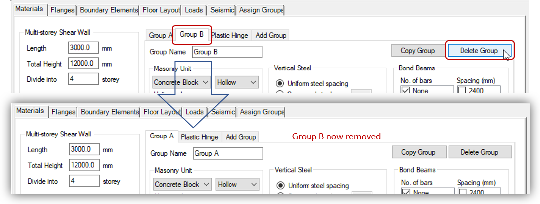
When a Group is deleted, it will no longer be listed in the row of Group tabs.
Note: The Plastic Hinge Group cannot be deleted because it must be available for the software to use for designs where the a plastic hinge region is required. Designs that do not contain a plastic hinge region simply will not use any property selections made within that tab. Similarly, a group cannot be deleted if it is the only non-plastic-hinge group remaining.
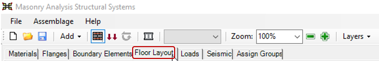
Floor Layout
As mentioned earlier, MASS places floors evenly along the height of the shear wall by default.
These floor locations where storeys and shear wall elements are divided can be changed using the “Floor Layout” tab. This is also where the floor thickness can be specified.
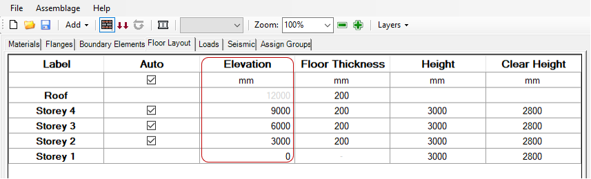
The Floor Layout tab includes a table within the input window as well as a simplified drawing of floor locations and storey clear heights in the drawing window. The Floor Layout tab view for a 12m tall, 4 storey shear wall is shown below before any changes have been made.
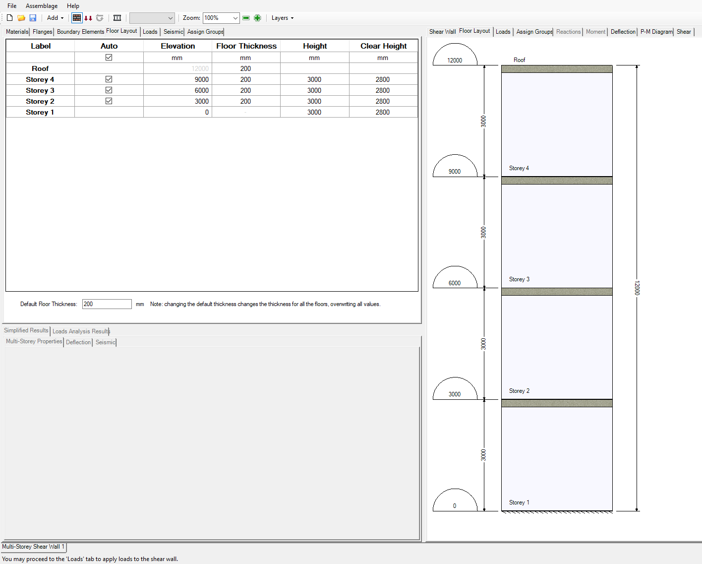
The input options area and various ways the layout can be altered is explained in the subsequent sections.
Label
A name or label is generated by MASS and assigned to each floor location. They are numbered in ascending order from the bottom to the top of the shear wall. Storey locations are defined based on the top surface of the floor slab at that location to the top surface of the floor above. Within that storey area, there is masonry wall built above that floor surface height as well as the depth or thickness of the slab itself, resting above that wall.
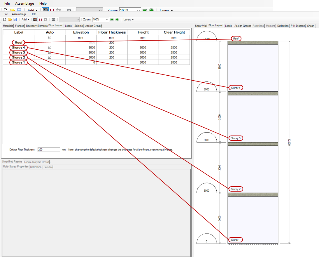
While each storey is shown as spanning from top of one slab to the next, the actual shear wall elements designed by MASS only includes the actual height of masonry wall, excluding the portion occupied by floor slab between masonry shear wall storeys.
These labels are generated by MASS and cannot be edited by the user. The top slab is labelled as “Roof” but has no corresponding masonry wall design.
Auto
The “Auto” column within the Floor Layout input tab is used for the user to indicate to the software whether or not a floor is placed at its location automatically or set to a static value. By default, all floors are placed automatically with the “Auto” box selected for each floor.
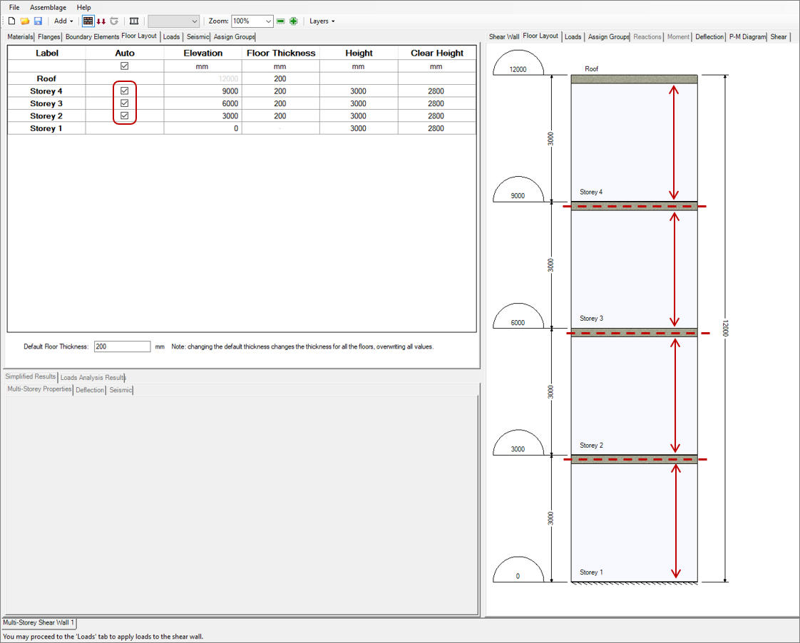
If the Auto box is deselected for a storey, the floor placed at that location will no longer automatically be adjusted to be evenly spread along the height. For example, the floor at the base of the second storey of a two storey shear wall is placed at the mid-height by default. If the auto box is deselected and the total height of the multi-storey shear wall is changed, the base of Storey 2 will remain at its original location, rather than move to the new mid-height location if it were still automatically placed.
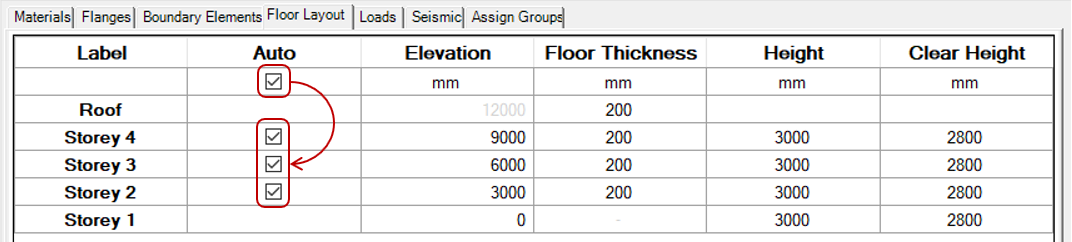
The top checkbox above the Roof row applies to all boxes beneath. Deselecting that box will do the same for all beneath and if any storey has been deselected, checking it will return that floor (and all others not selected) back to the being automatically placed by MASS.
When some floors have the auto box unchecked, all remaining floors are automatically placed to be evenly spread between the manually placed floors. This can be used to quickly model a shear wall where the storey heights change from one value for the first few floors to another for the remaining.
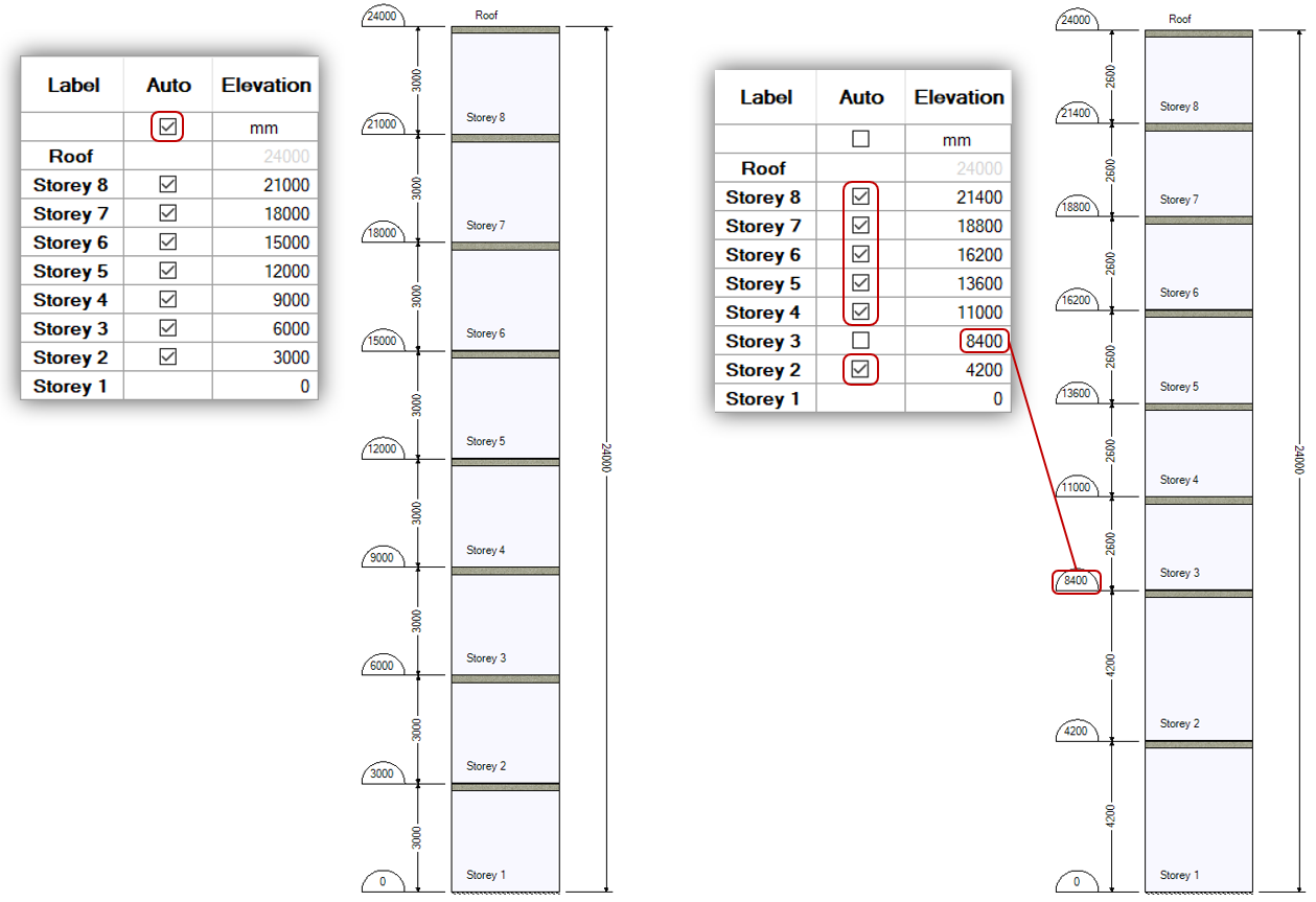
For this example, MASS will start by spreading the floor locations evenly along the entire height. If the first two storeys are taller than the remaining, simply changing the location of the bottom of the third storey and the software will shift the remaining floors to maintain two different uniform values.
Automatically placed floors will always be evenly spaced by MASS between the elevation at grade, roof level, and any manually placed floors in between.
The Auto feature is available for convenience and can always be disabled by deselecting it for all floors. Before getting upset and throwing your computer across the room, try turning off the “Auto” placement feature and enter the storey heights manually to ensure they are exactly where they are supposed to be.
Elevation
The Elevation column contains an input field for where each floor can be manually placed.The values displayed by default correspond to where they have been placed automatically by MASS. Changing these values (or even re-entering the same, existing value) will de-select the Auto box as well as specify a static location for that top floor surface.
Floors must always be placed in sequential order. For example, the base of a manually placed Storey 3 cannot be edited to be above a manually placed Storey 4. In the event where all surrounding floors are automatically placed by MASS, those floors will shift around the floor being edited. Their updated locations are then reflected in the elevation column.
For instances where each floor is placed automatically by MASS, this column can still be a useful location to view the position of each floor on the shear wall’s elevation, in addition to being shown on the layout drawing.
Elevation locations are measured in mm relative to grade. By default, the elevation at grade is assigned a value of 0mm by MASS and all elevations along the height are relative to this location. If the elevation at grade is modified by the user, all other elevations are updated to maintain the same relative position within the wall with new elevation values.
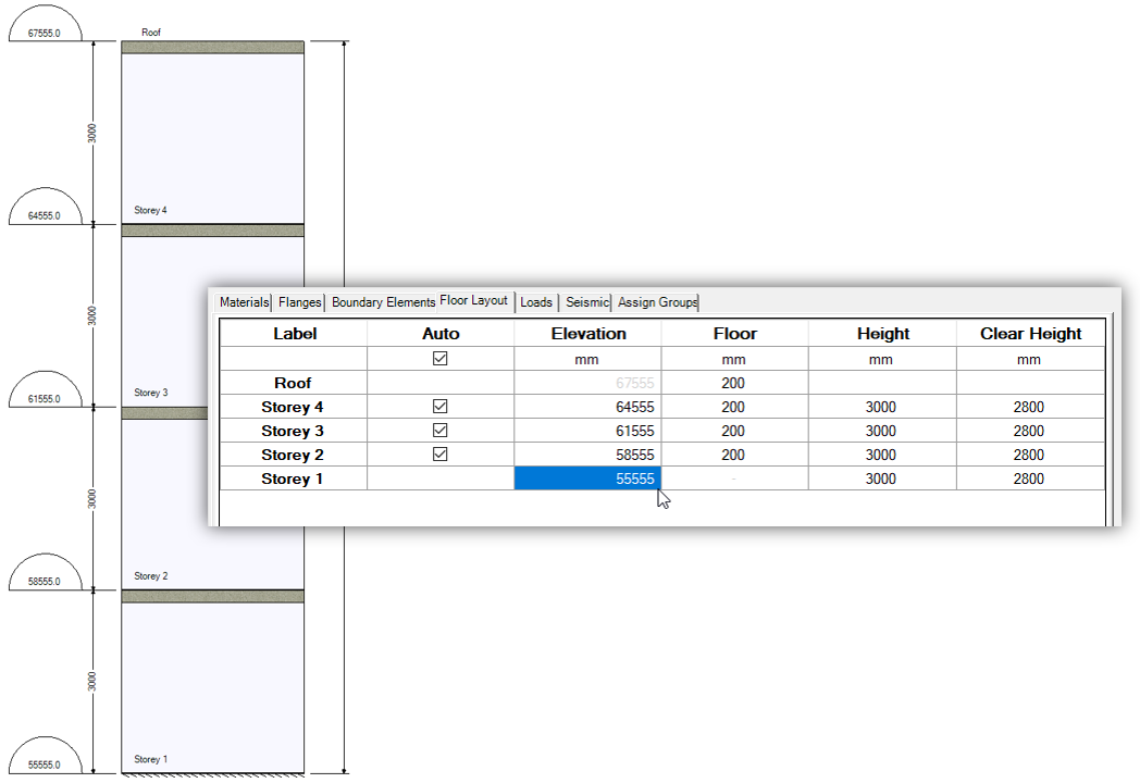
Note: Grade elevation is available for changing as an option for users to match construction documents. Changes made here should have no impact on design.
The Roof elevation cannot be edited in the Elevation column. To change the roof location, return to the Materials input tab and adjust the Total Height input field.
Floor
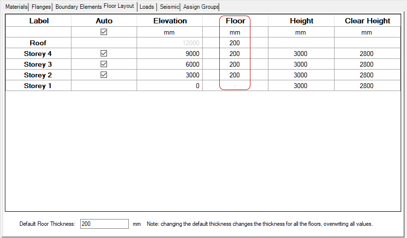
The Floor column represents the thickness of each floor, measured from the top surface downward into the storey beneath. Floor thicknesses can be changed for individual floor levels by editing the values shown in the Floor Layout input window column to the right of the Elevation column.
For example, if the floor thickness is increased by 50mm at the location where storey 2 begins, the thickness of the floor is increased from the masonry on the first storey.
The total thickness of a floor cannot be increased beyond a value that would result in the height of the storey beneath dropping below the nominal height of one masonry unit.
Default Floor Thickness
The thickness of all floors can be changed by modifying the value shown in the Default Floor Thickness input area, beneath the table.
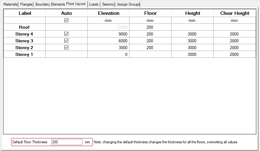
As noted to the right side of the input field, changing this value will result in all current floor thicknesses being overwritten, including any manually modified by the user. This field serves as a convenient way to change the floor thicknesses of each floor without having to click and enter in the desired thickness for each floor.
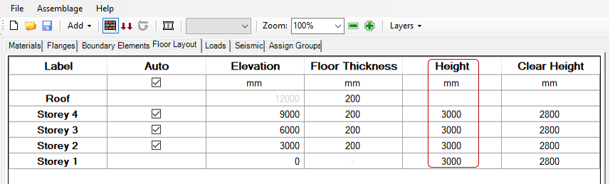
Height
The storey height cannot be modified by the user and serves as an output column for reference when making changes to storey or floor location.It is shown to the right of the Floor Thickness column.
The figure below highlights the height of Storey 4 in the Floor Layout input window matching the value shown in the drawing.
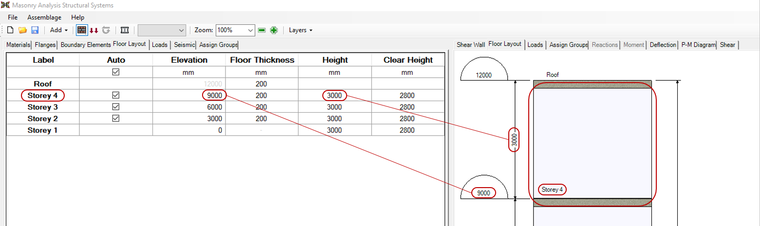
The height of each storey is measured from the top surface at the base of the floor to the top surface of the floor above. These will include the thickness of the floor resting upon that storey’s shear wall element.
Clear Height
The clear height for a storey refers to the clear distance between the top of the floor slab beneath a shear wall element and the underside of the slab above. It cannot be modified by the user and serves as an output column for reference when making changes to storey or floor location. These values are not displayed in the drawing window but are used as the Height entries for the design of each shear wall element.
![]()
The clear height of each storey is equal to the storey height minus the thickness of the floor above.
Applying Loads
To apply loads to a multi-storey module, the loads input window can be opened by selecting the Loads tab or by clicking the load button in the top toolbar.
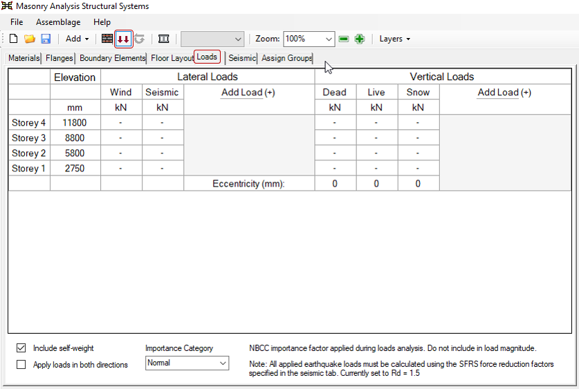
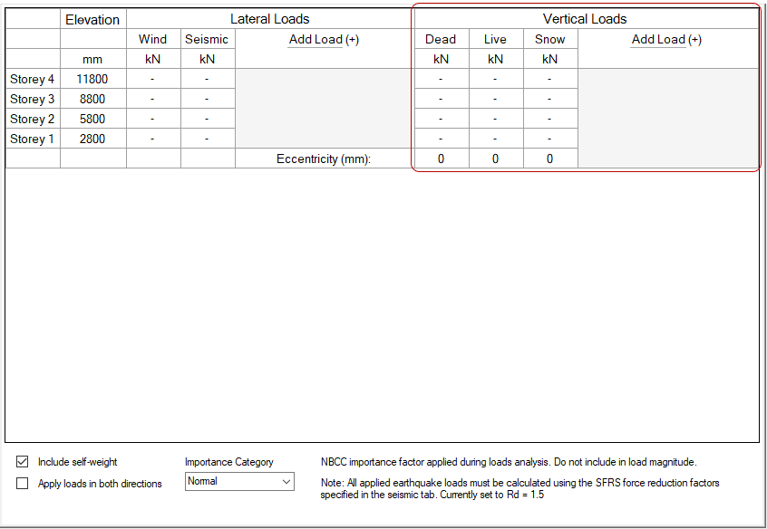
Within the Loads input window, there is a table that is used to enter loads along the height of the multi-storey shear wall. Loads can only be applied directly to the top of each wall between floors. While floors have been placed based upon the top surface of each shear wall element, all lateral and vertical loads are applied beneath each floor elevation, directly upon the element itself.
Using the table within the input window, lateral and vertical loads can quickly be applied along the height of the structure. The subsections below explain the use of this table. There are four main columns along the top row: Label, Elevation, Lateral Loads, and Vertical Loads. The Label and Elevation columns are for reference when applying a load to a particular location on the structure.
Just because Wind, Earthquake, Dead, Live, and Snow loads have Columns present by default does not mean that they must be completely populated in order to perform a design. If no loads are entered in any loads column then the design will proceed without and loads of that type applied.
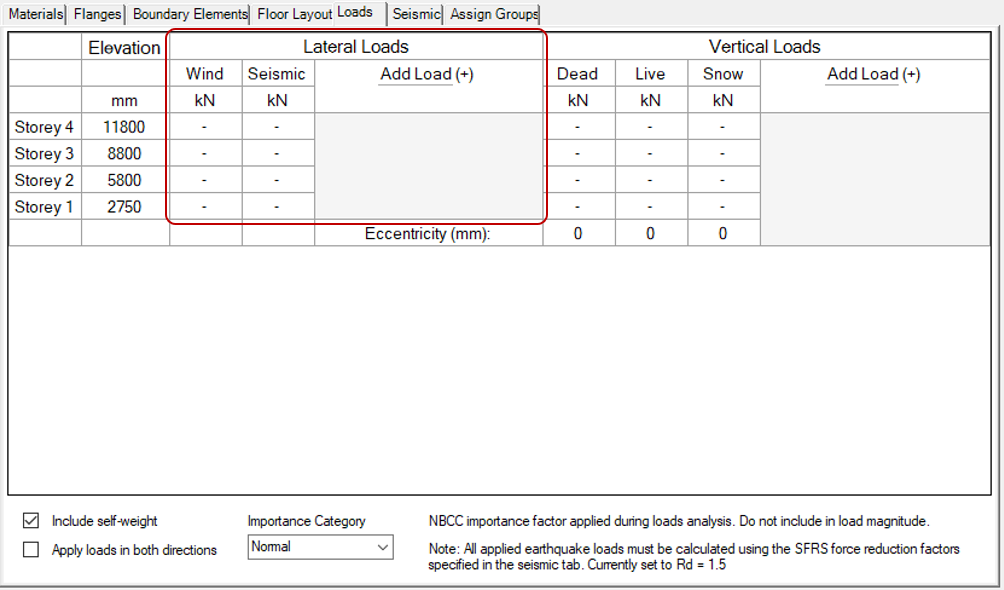
Lateral Loads
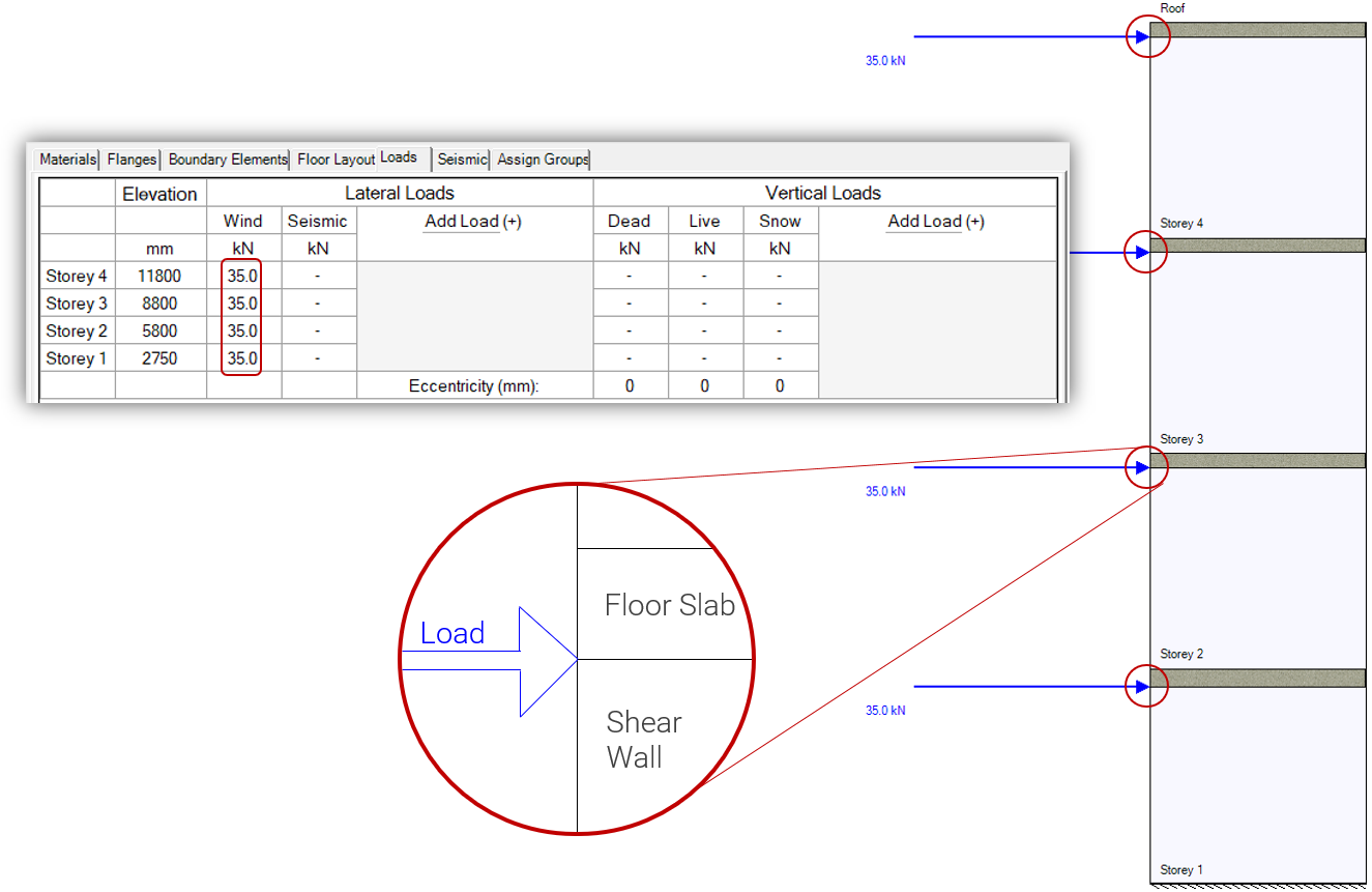
Horizontal or lateral loads can be applied under the Lateral Loads main column in the Loads input window. There are two lateral load types available by default: wind and earthquake.
The pre-formatted columns can be populated by the user by starting with the loads at the top storey. Recall that they are applied directly to the shear wall element, beneath the slabs resting above.
Loads of a different type can be added by clicking the “Add Load (+)” button to the right of the second default column for earthquake type loads.
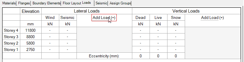
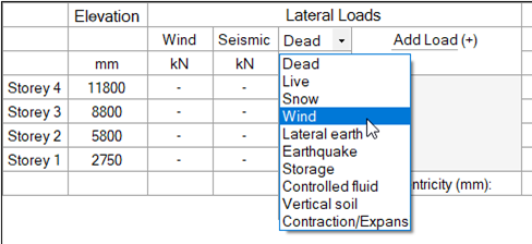
When a new load column is added, it appears to the left of the “Add Load (+)” column beside the existing lateral loads. The type of the added load column can be selected by clicking on the drop-down menu in the cell above where the units are listed.
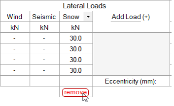
Added load columns can be removed by clicking on the “remove” bottom which appears at the bottom, beneath the cell where the Storey 1 load would be applied.
There is no limit on the number of allowable loads imposed by the software.
Note: All loads must be applied as unfactored forces, measured in kN. The ability to specify loads in other unit selections including imperial has not been extended to multi-storey shear walls.
Vertical Loads
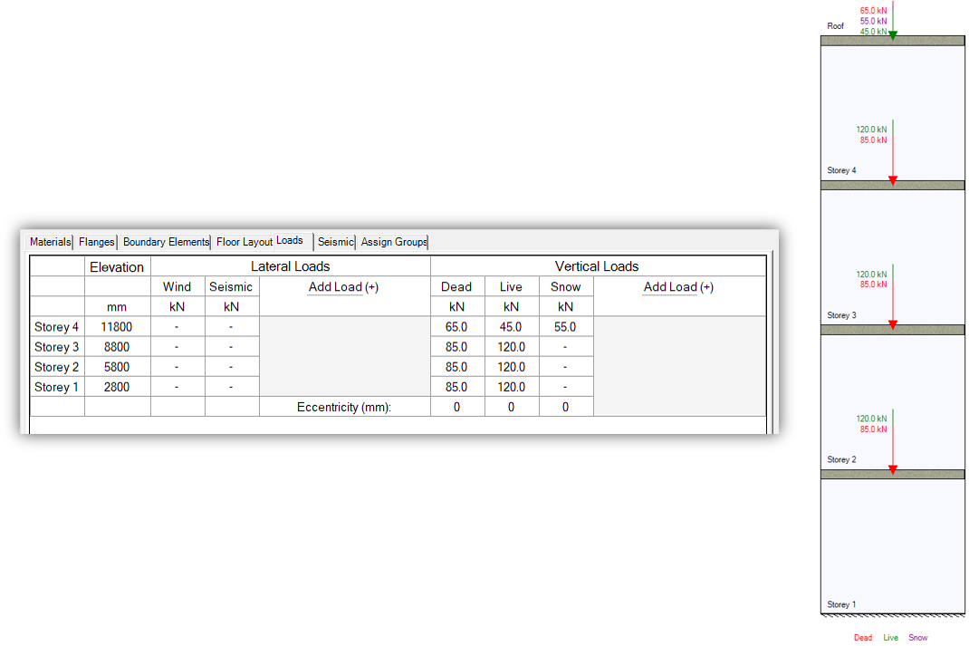
Vertical (or axial) loads are applied under the Vertical Loads heading in the Loads input window. By default, there are three columns shown for Dead, Live, and Snow type loads that can be entered using the cells for each storey.
As loads are input into the table, they appear on the drawing window for quick user reference.
The same process outlined in the Lateral Loads section can be used to add and remove additional load types.
Note: All loads must be applied as unfactored forces, measured in kN.
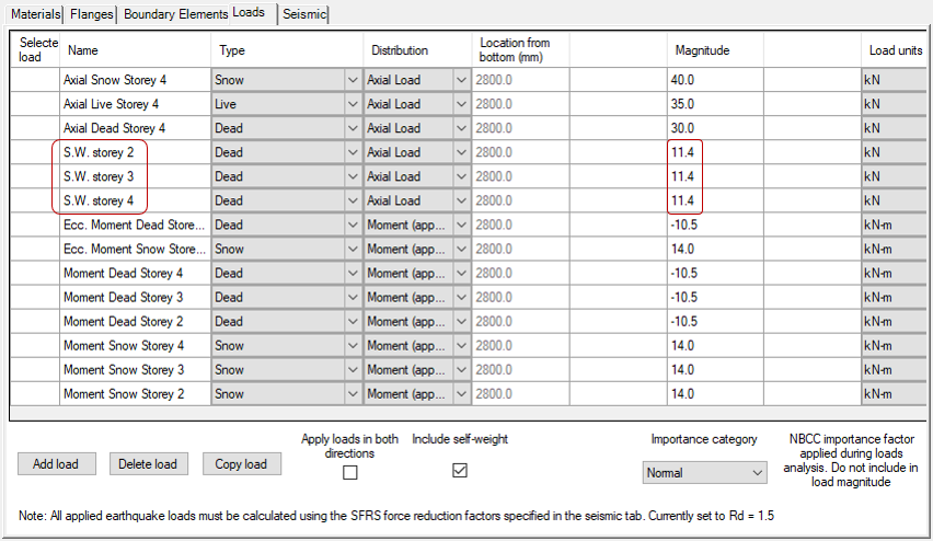
Eccentricities
Vertical loads are applied at the middle of the wall with no eccentricity by default. In the case of a uniformly distributed load landing on a shear wall section from the floor slab resting upon it, the resultant force is balanced and also applied at the middle of the wall, resulting in zero net eccentricity.
In the case where a vertical load rests at a different physical location along the shear wall or there are different tributary areas of the floor resting upon the wall, it may be necessary to apply the axial load at an eccentricity.
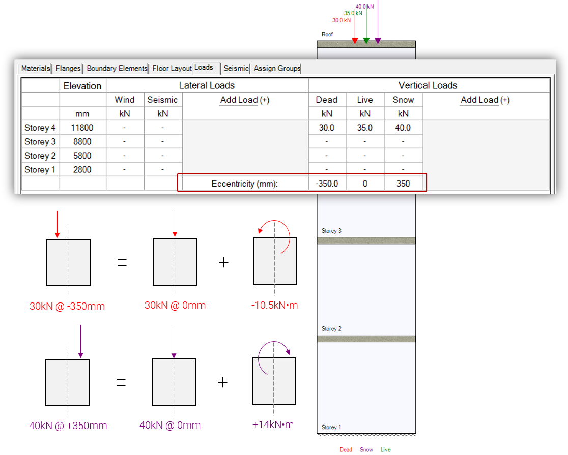
For the example summarized above with the input area superimposed above the drawing, the applied axial dead load is applied with an eccentricity of -350mm, placing it 350mm to the left of the default position. This will result in an applied moment of 30kN multiplied by 0.35m, or 10.5kN*m resulting from the eccentricity. The default location eccentricities are measured from is the location of an axial load at which there are no resulting applied moments on shear wall element below. The live load with an eccentricity at the default value of zero will be resisted by all shear wall elements below but there will be no accompanying moments in addition to those axial loads. The snow load of 40kN will generate an applied moment of 14kN*m resulting from the +350mm eccentricity.
MASS models the axial load eccentricity on individual storeys by applying it at the default position and also applying a moment equal to the magnitude multiplied by the eccentricity.
The full effect of adding an eccentricity to a vertical load is explained in further detail in the load distribution page. An applied moment is added to the design of each shear wall element design beneath that location, affecting the factored moment for all load combinations containing that eccentrically applied vertical load.
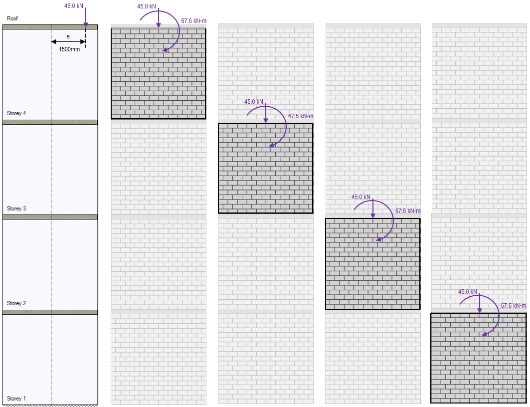
In the example figure above, the snow load used in the multi-storey load distribution example has been applied at a distance of 1500mm from the middle of the wall. The result is a snow type applied moment that is experienced by each shear wall element beneath the location where the vertical load has been applied. For more information, click here to visit the Multi-storey Shear Wall Load Distribution page.
Note: within the design for each shear wall element, there is no further acknowledgment of the axial load eccentricity beyond the presence of the applied moment. The calculation and application of this moment is the software’s way of taking the eccentricity into account.
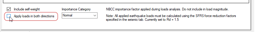
Apply loads in both Directions
Selecting the “Apply loads in both directions” check box at the bottom of the loads input window will result in MASS analyzing and designing each shear wall element for right-to-left and left-to-right loading directions. By default, the software will only apply the loads as shown in the drawing window.
More information regarding the direction of loading can be found on the shear wall element design steps page (click to open).
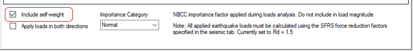
Self-weight
MASS must complete a shear wall design starting from the top and working downward in order to properly and sequentially apply accurate self-weights on all designs below. The “Self-weight” check box is enabled by default.
When self-weight is enabled, the software will add an additional axial load on all designs further down the wall equal to the weight of the each storey. For example, the first storey of a four storey shear wall with self-weight enabled will have additional axial loads from the second, third, and fourth storey designs – something that MASS has already calculated and applied.
The initial design of a multi-storey shear wall starts at the top storey and works down the structure because moment and shear design are a function of axial load and axial load depends on the self-weight of what rests above. More can be read about the multi-storey design process by clicking here. Additionally, the shear wall element design process is outlined here.
Seismic Tab
Once all of the unfactored loads have been applied, the next stage is the Seismic tab, found to the immediate right of the Loads tab.
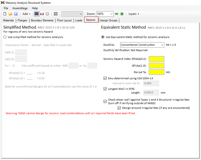
Seismic input fields are only required for designs containing an applied earthquake load.
The Seismic tab is explained in full on its own dedicated page, found by clicking here.
Assigning Groups
Upon completion of the Seismic stage (or Loads stage if no seismic loads are applied),the “Assign Groups” tab is the final step in creating a multi-storey shear wall that is ready to be designed.
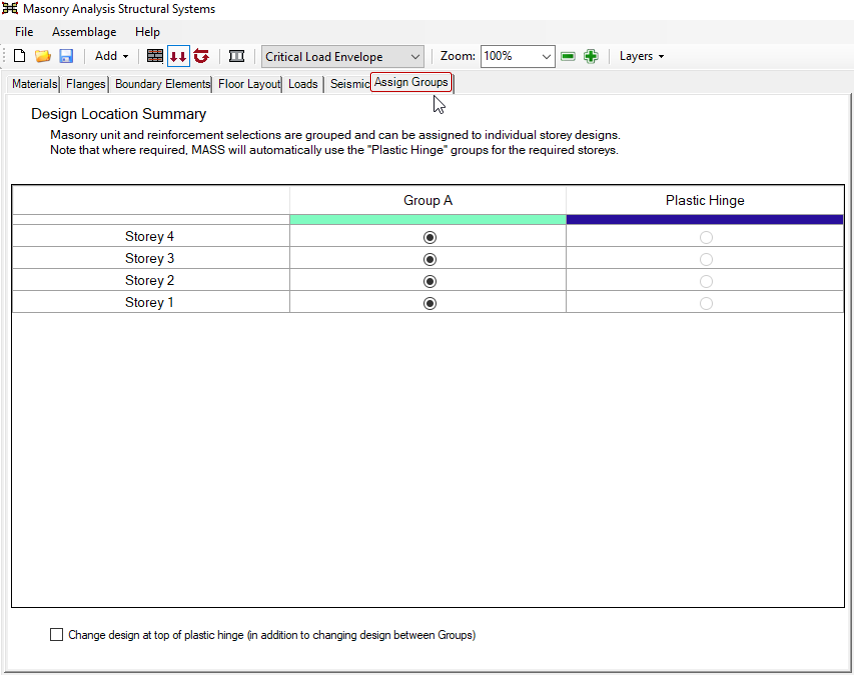
By default, all groups start under Group A.
This tab is not required and if it is left before designing, MASS will automatically use the Group A properties for all designs not with the plastic hinge region. Designs not containing a plastic hinge will use Group A along their entire height.
Changing Design Between Floors
MASS defaults to using Group A properties for the full height. This results in uniform designs that are uniform from top to bottom of the multi-storey shear wall. Assigning groups to individual parts of the shear wall is the user’s way of breaking up design properties into distinct sections along the height of the wall.
In order to assign the properties from a different group to part of the wall, the additional group must first have been created in the materials tab, covered earlier on this page. The plastic hinge does no count as an additional available group because it behaves differently, covered in the section below. If a new group has been created, named Group B by default in MASS, it can be assigned to individual storeys by selecting the bubble control shown below:
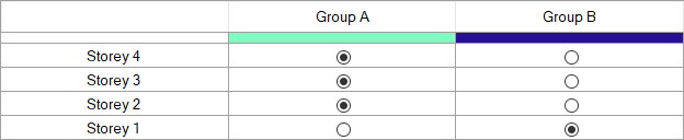
Each row corresponds to the storey to be changed and each column represents an available group. The example shown in the image above depicts a shear wall where Storey 1 is assigned the Group B properties whereas Storeys 2 through 4 are still assigned the properties specified in the default Group A.
Note: While it is not required that Groups contain adjacent storey designs, it is recommended practice as the lowest storey will typically govern what is used within all shared storeys within that group.
Plastic Hinge Group
The plastic hinge group is only ever assigned by the software and cannot be overwritten by the user. MASS determined based on the inputs form the Seismic tab whether or not a plastic hinge region is required and if it is, the software calculates it’s height before any design work has been performed.
For designs which require the use of a plastic hinge region (ductile shear walls or non-squat moderately ductile shear walls), any storeys that encompass part of that designated region will switch from their default group properties to using the Plastic Hinge properties.

The hashed area shows the minimum required portion of the shear wall that must be designed in accordance with the added plastic hinge requirements within the CSA standards.
In the example shown above, the required height of the plastic hinge location is less than that of the bottom storey. It is the default setting for MASS to design all storeys containing at least part of the plastic hinge region be designed using plastic hinge requirements. This can be changed by un-selecting the checkbox, demonstrated in the below:
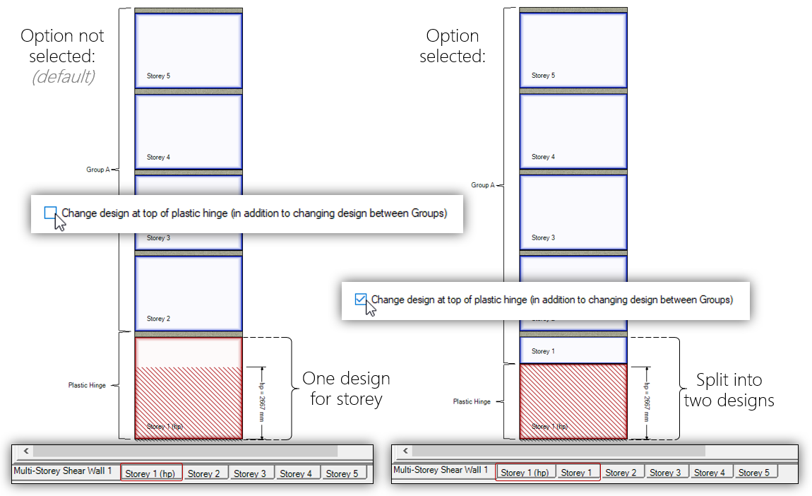
When this option is disabled, MASS breaks apart the storey element into two separate elements: the above portion not designed to plastic hinge requirements, and the actual plastic hinge region. This option allows for user to specify multiple cross sectional designs within one floor of the structure. For most multi-storey scenarios where the storey height is not much larger than the required plastic hinge region, the default setting of rounding the region height upward to match floor locations may be preferred for simplicity. However, very tall shear walls where the plastic hinge region requires signification more grout and reinforcement may benefit from splitting an element into two parts.
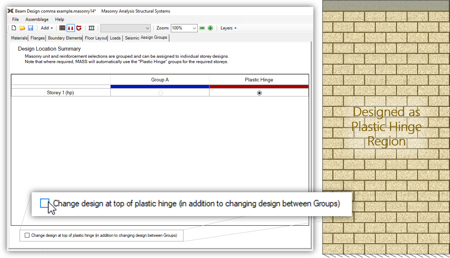
Below is a single storey design where the full height is designed to plastic hinge requirements:
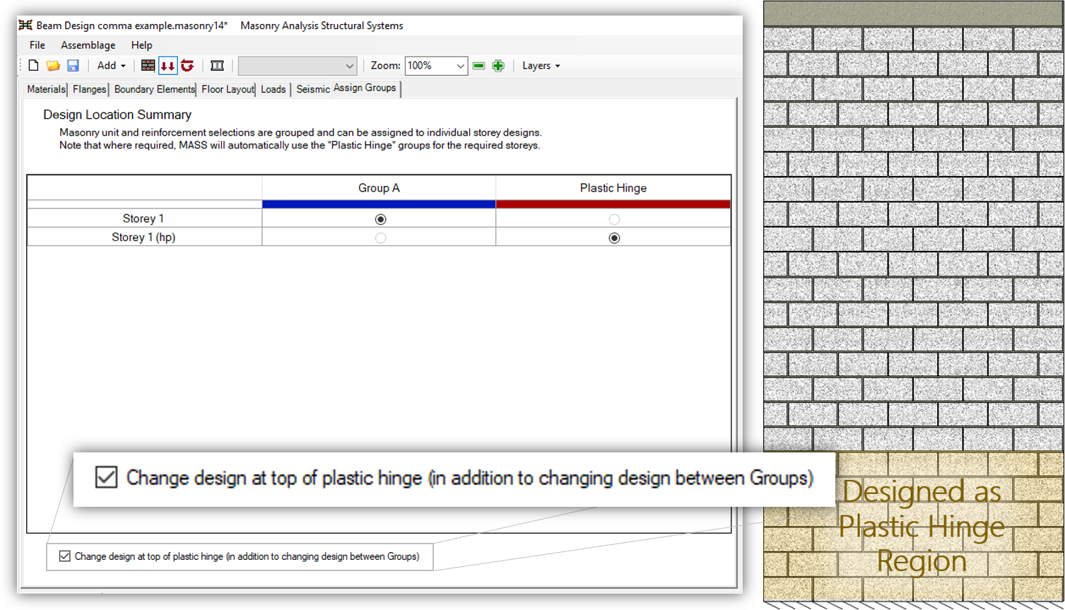
In contrast, the image below shows the same shear wall broken into two elements where only the bottom third must be designed to satisfy the plastic hinge requirements:
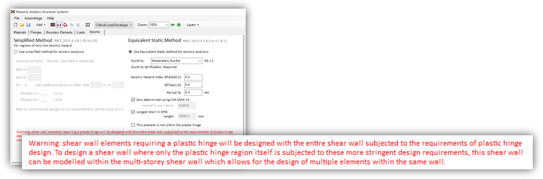
Additionally, there is a message displayed for designs within the Shear Wall Element module letting the use know they have this option using the multi-storey module.
For more information on this feature and how it can be used in design, click here for a post covering the single storey applications of the multi-storey shear wall module.
Note: For designs using boundary elements to achieve higher maximum strains, the plastic hinge will be automatically determined in accordance with CSA S304-14: 16.10.3, regardless of whether the higher strains are used or not. This decision was made to avoid changing plastic hinge height midway through the design process.
Design Stage
To proceed to the Design Stage, press the icon to the right of the Loads button, shown below:
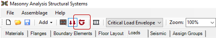
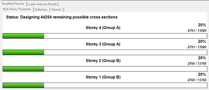
The icon will changed from grey to red when enough of the shear wall geometry and loads have been applied. Selecting the Design Stage will move the blue outline seen above around the Loads icon to the design stage icon. Once the Design Stage has been selected, MASS will automatically commence a multi-storey shear wall design. The loading screen showing the progress can be seen below:
Understanding the Results
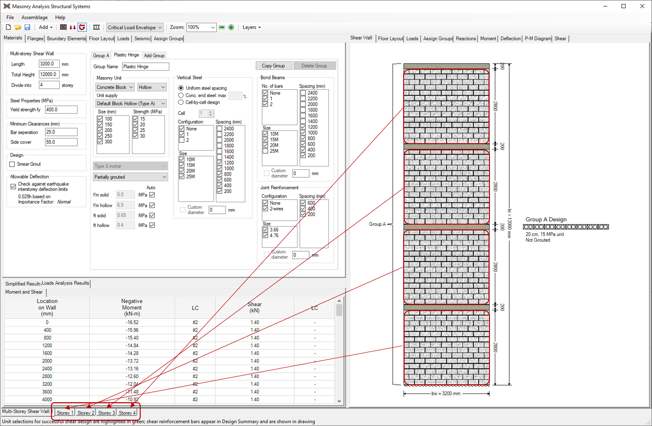
When a design is completed, the loading screen is automatically replaced by the Multi-Storey Properties results tab, there an overall summary of the shear wall can be found.
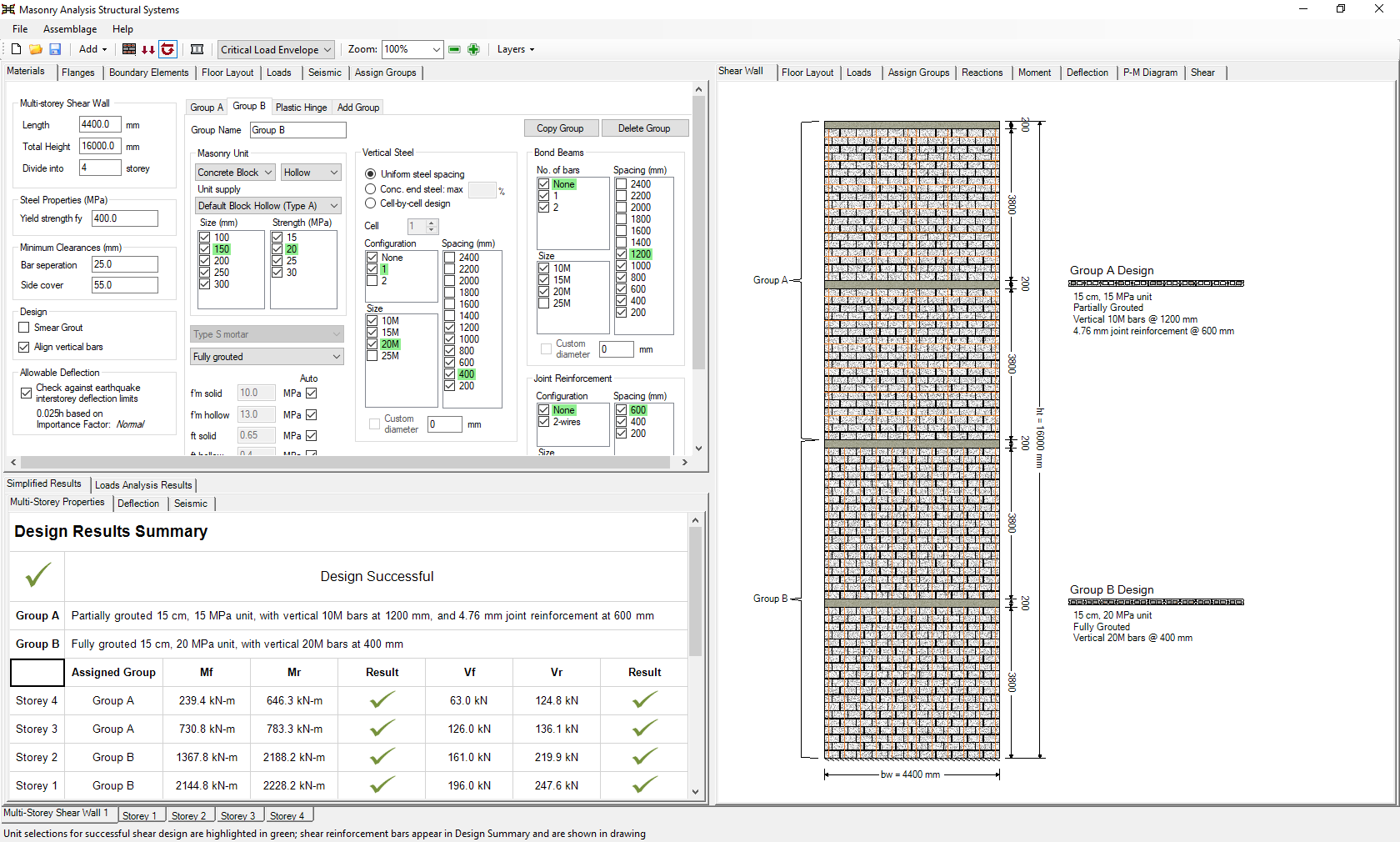
In addition to the highlighting of successful properties in green for each group used in the design, the properties used are displayed in the drawing beside the shear wall elevation in the main shear wall drawing window.
Successful Design Results
Design Results Summary
The overall status of a completed multi-storey design can be seen at the top of the results window. The text “Design Successful” is shown in the absence of any failures triggered in the storeys within the multi-storey assemblage.
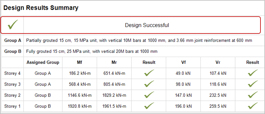
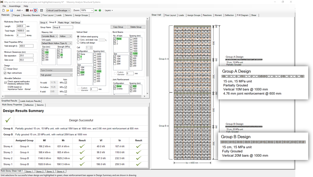
Beneath the overall design status, a summary is shown for all Groups that are assigned within the structure. This includes the masonry unit properties, vertical reinforcement size and spacings, and horizontal size and spacings for both bond beams and joint reinforcement.
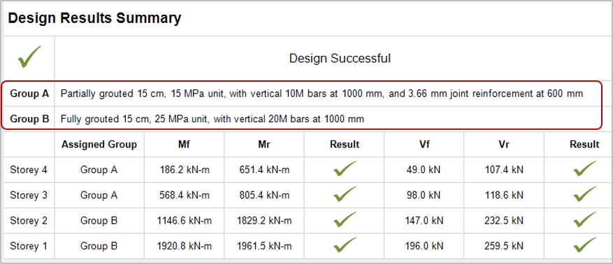
Note: Groups that have been specified but not assigned to any storeys will not appear in this summary.
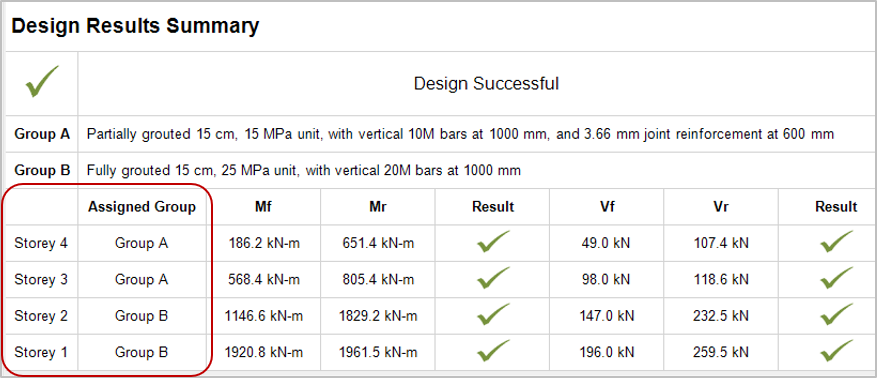
The left portion of the summary table shows which groups have been assigned to which shear wall elements along the height of the structure. Refer to the section above to see which properties are used for the Groups that are referenced here.
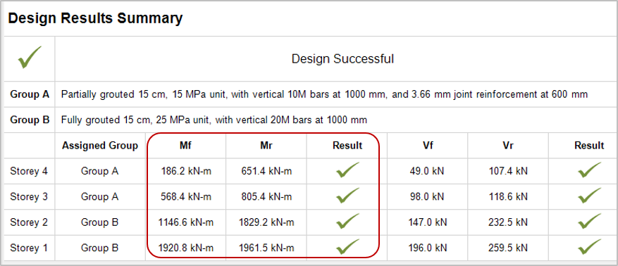
The highlighted section below summarizes the moment design results for each storey. The factored moment, moment resistance, and design status are shown here.
The highlighted section below summarizes the shear design results for each storey. The factored shear, shear resistance, and design status are shown below.
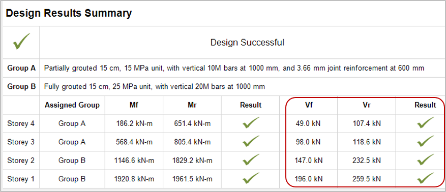
Note that since both diagonal shear and sliding shear are each performed as part of this section, where the lesser resistance is reported as critical.
P-M Diagrams
If a design fails resulting from axial loading (part of moment design) or has insufficient moment capacity, the P-M Diagram can be a useful place to look.
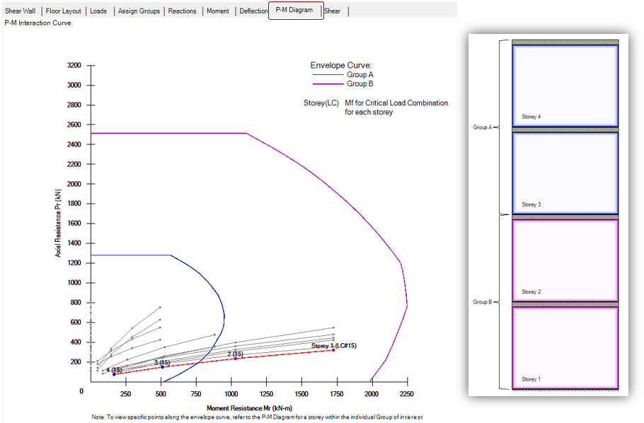
A drawing of the assigned groups is shown to the right to demonstrate where in the shear wall each Group has been assigned. As can be seen in the screen shot above, the smaller envelope curve corresponding to the upper two storeys is only adequate to resist the loads at that location, whereas the lower two storeys must be designed for larger bending moments, axial loads, and shear forces. This can be seen by the larger envelope curve.
Failed Design Results
If a design is not successful, MASS will display the failure message triggered by any of the shear wall element tabs contained within the multi-storey assemblage.
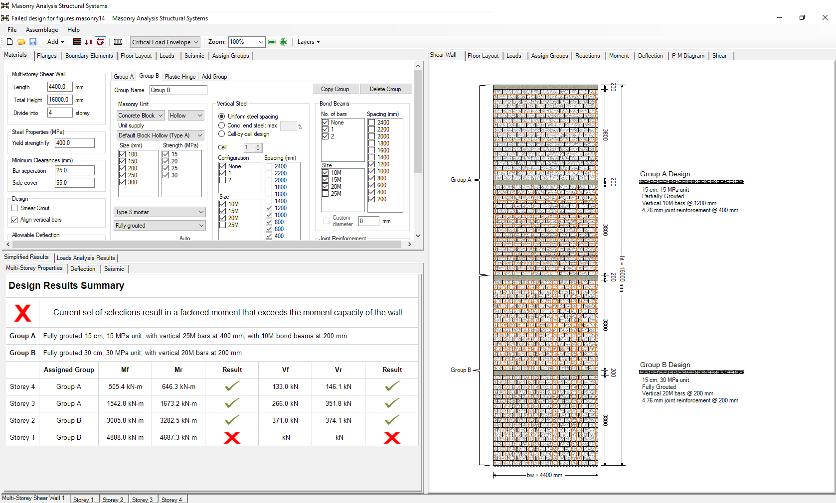
Note: There can be multiple failure messages that are triggered internally during the design process. Addressing the message shown will not necessarily cause the design to become successful, as the other reasons for the failing design may still be present within the assemblage.
For the design of any one storey, the results can be further investigated by selecting the storey tab for the element in question along the bottom of the screen.
P-M Diagrams
When it comes to capacity design and in particular, moment design, the P-M Diagram drawing can be a helpful resource in seeing which parts of the structure are insufficient. The P-M Diagram below shows four envelope curves – one for each of the four storeys – where the design has failed before equalization has occurred.
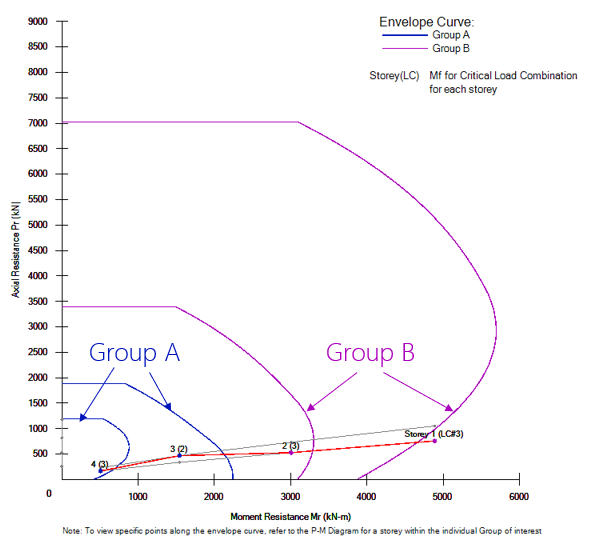
If the design were successful, the group equalization stage would have updated all designs within each group to share the same properties and only two curves would be shown. In this case, the load combination points for each storey are within their corresponding envelope curves except for the base of the structure at Storey 1 which can be seen outside the envelope curve for that storey.
If a design is not successful and the reason is not immediately apparent, consider getting in touch with MASS technical support, provided through the Canada Masonry Design Centre.
Continue Reading: Multi-Storey Design Strategy