Latest Software Blog Posts
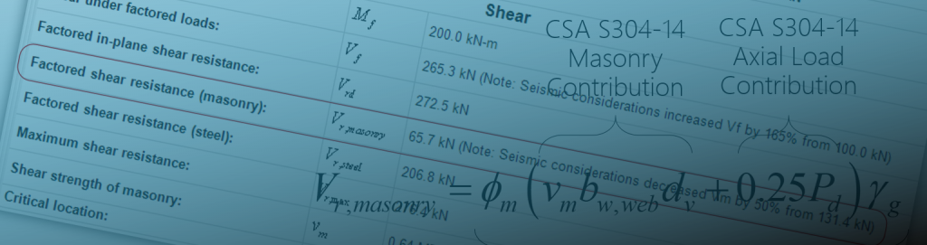
Checking Vf,seismic for a Multi-Storey Shear Wall
Taking seismic effects into account in MASS can be confusing. Seeing factored shear forces scaled up by over 100% in some cases may seem larger than expected.
The main post found here outlines the clauses being invoked here where the requirements are broken down into two parts: A and B. This post serves as a follow up to the single storey and shear wall element example shown here.
Disclaimer: This post is exclusively intended to provide insight into the approach taken by the MASS design software in interpreting a CSA S304-14 code compliant seismic design. It is up to the professional discretion of the designer to input an appropriate layout, boundary and loading conditions, interpret the results, and determine how they should be incorporated into their designs. As per the end user license agreement (and also recommended within PEO’s guidelines for using engineering software), a tool cannot be considered competent and reliance on a tool does not relieve the user of responsibility.
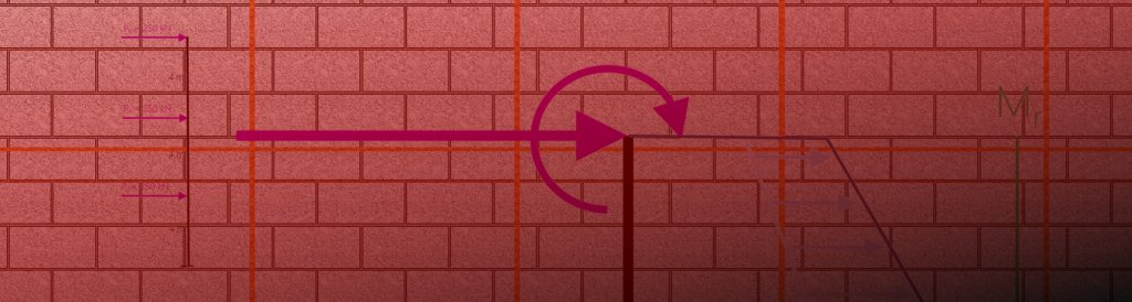
Consider a 12 m tall conventional construction shear wall where the in-plane shear must be performed in accordance with CSA S304-14: 16.5.4:
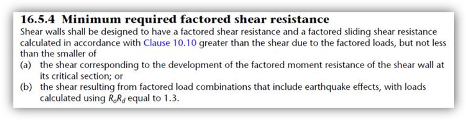
The lateral point loads are applied every 4 m at floor locations. The determination of the limit from part (a) is shown as follows:
Each lateral point load has a magnitude of 250 kN and has the type “Earthquake”, invoking the seismic effects that need be considered.If the shear wall has a cross section moment resistance of 9,600 kN·m, by how much must the loads be scaled upwards to ensure that the wall will fail in flexure?
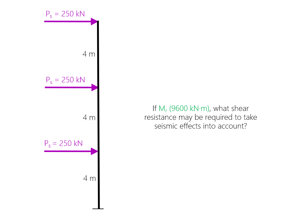
The first steps are to compare the moment resistance to the factored moment. The factored shear at the base of the wall is also needed to determine the scaled up seismic shear force.
As shown below: the factored bending moment at the base of the wall is 6000 kN·m and the factored shear force is 750 kN.
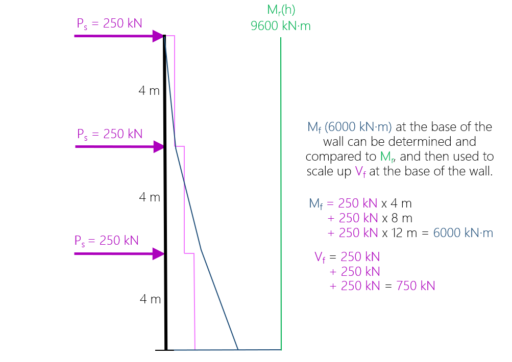
Comparing these two moment values to one another, it can be determined that the moment resistance is 1.6 times the moment experienced at the base. As a result, the applied loads can be scaled up by that same ratio to determine the factored shear that may need to be designed for. This ratio can be applied to the applied loads which are then used to recalculate Vf or it can also be applied directly to the shear (effectively doing the same thing)
At the end, it can be confirmed that the Mf = Mr condition is still true by recalculating Mf based on the scaled applied lateral loads. As seen above, these two values are found to be equal to 9600 kN·m. This check is not required but serves as a handy way to check that no mistakes were made along the way.
Whether or not 375 kN is the magnitude needed to satisfy CSA S304-14: 16.5.4 depends on the limit outlined in part (b).
Checking against the limit from part (b)
I specifically say that Vf may need to be scaled up by that ratio because the lesser of parts (a) and (b) are required for any seismic shear wall design. Since it is less than the scale factors for any of the three reinforced masonry SFRS categories, we can conclude in this case that the shear must be scaled up by 60%.
A summary of the increases resulting from part (b) is shown below:
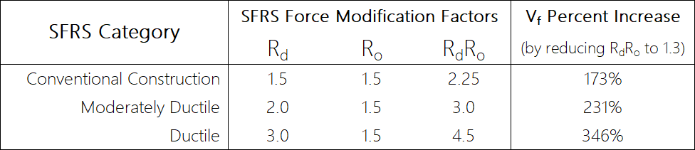
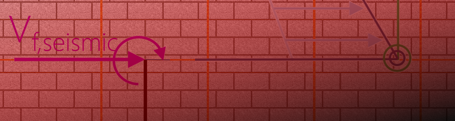
For demonstration sake, replacing the product of RdRo with 1.3, the initial factored shear force experienced at the critical section can be multiplied by the ratio of RdRo to 1.3. In this example, the seismic shear in part (b) is shown below:
Vf,seismic = Vf x RdRo/1.3 = 750 kN x (2.25 / 1.3) = 1298.1 kN [Does not govern]
Since Vf,seismic in part (b) is less than the value of part (a), only the lesser limit be taken as the factored in-plane shear resistance that the shear wall must be designed to resist, taking into account seismic considerations.
More information regarding part B requirements can be found on the main Vr,seismic post here.
It should also be noted that different SFRS types reference different moment resistances so the percentages shown cannot be directly compared to one another. Moment resistance, nominal moment resistance, and probable moment resistance each have different values and will result in different degrees by which Vf is scaled to consider seismic effects.
To return to the main seismic shear article that likely bounced you to this page, click here. For a bonus post explaining the differences between the example here performing the analysis at the element level which is what MASS does, clock here.
Additional reading: Bonus Post: What happens when you treat a Multi-Storey Design as an Element when Increasing Factored n-Plane Shear ?