Latest Software Blog Posts
Understanding the χ factor and how it can help with masonry beam design
Beam design can be tricky but understanding the factors at play makes it easy to design beams with masonry
This article originally was featured on the MASS Software Blog, formerly hosted on the software section of the Canada Masonry Design Centre website. CMDC is the authorized technical service provider for the MASS Software
Have you gotten design failure messages along the lines of “there is too much tension steel for the steel to yield” when trying to design masonry beams for moment and deflection?
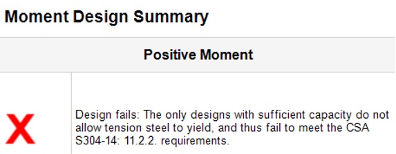
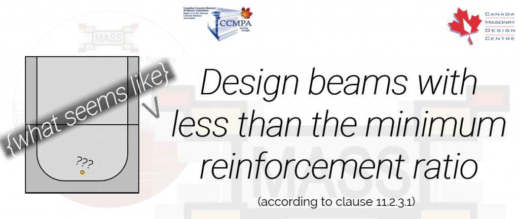
This is likely the second most common question (after “Why can’t I place stirrups in my masonry beam?”) but unlike the stirrup question, this issue is not solved by a codes and standards update. Masonry beams are required to be under-reinforced to ensure ductile failure which is why tension steel yielding at failure is a mandatory design requirement. One of the keys to satisfying this clause lies in leveraging the use of the “chi” factor which is the factor accounting for the direction of compression stress within a masonry member.
Defining the chi factor
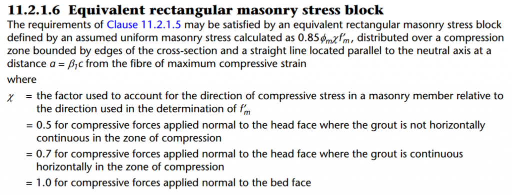
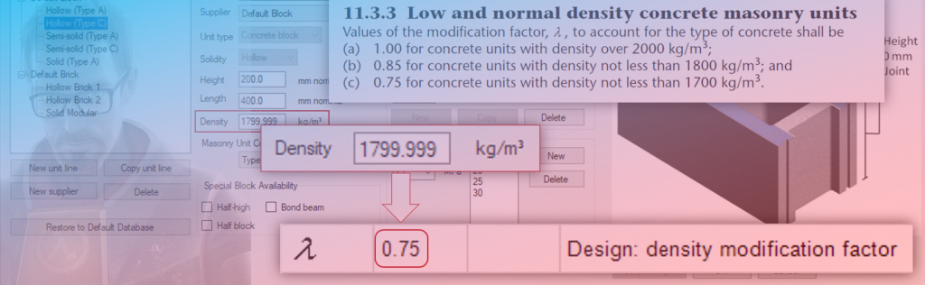
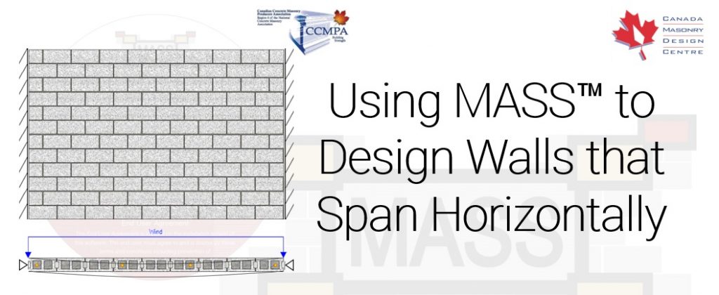
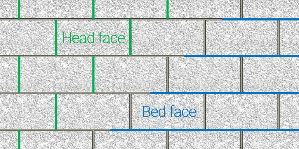
This factor mainly differentiates the compression force used in out of plane walls and shear walls from the force used in beam design (or the less common horizontally spanning out of plane wall design). The full magnitude of f’m is measured perpendicular to the bed face (or head joint when referring to the mortar joint itself) which is why the chi factor is 1.0, having no effect on the ultimate 28 day strength of masonry. f’m is modified for compressive stress perpendicular to the head face (or head joint when referring to the joint itself) by up to 50% depending on whether the grout is horizontally continuous.
The distinction between being able to use 50% or 70% of f’m is decided by whether there are any masonry webs interrupting the grout in the direction of the compression forces. To understand which value of chi to use, a good start is to look at the masonry units used in beams and identify where there are and are not horizontal interruptions of the grout once it is poured.
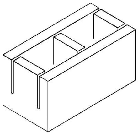
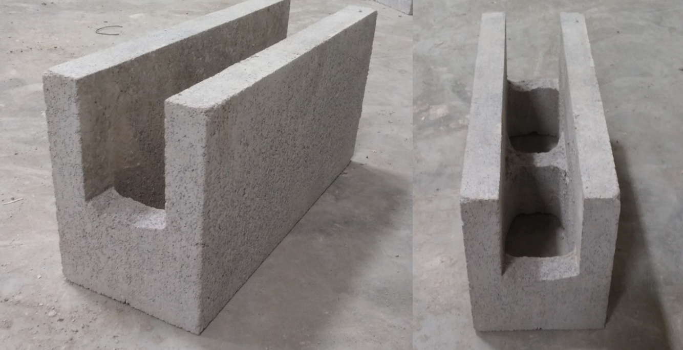
Knockout units are used when horizontal bars placed within a wall or beam. These units are designed so that the mason can easily “knock out” the top of each web to accommodate the steel but this open area also allows for a horizontal strip of uninterrupted grout to be present within the beam. The knockout depth refers the the distance between the web and the top of the unit. This value is referred to in MASS as dknock or dknockout seen below. It can be found in the Detailed Beam Properties tab in the software’s output.
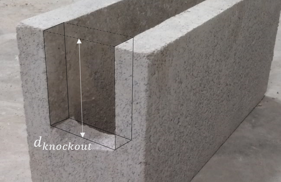
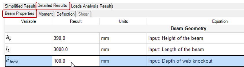
The default value is 100mm, or half of the nominal height of a standard masonry unit however it can be changed in the Minimum Clearances section of the input window.
What affects the chi factor?
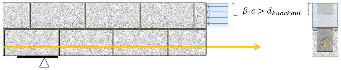
Below is an example where the depth of the compression zone exceeds the knockout depth. when this is the case, chi has a value of 0.5 and only 50% of f’m is used. This is a result of the remaining webs horizontally interrupting the grout.
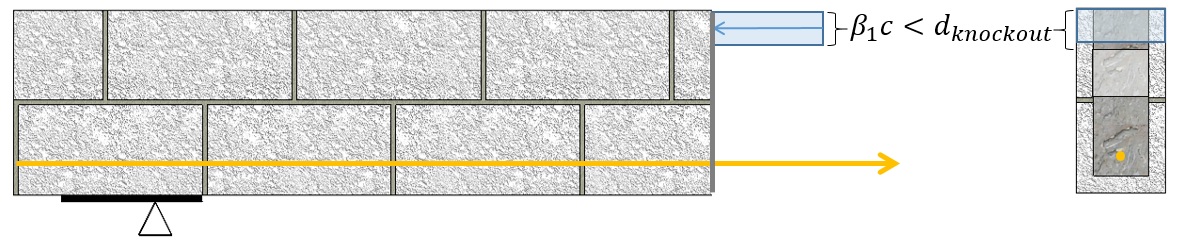
Alternatively, when the depth of the compression zone is less than the knockout depth, there is no interruption and the larger 0.7 chi factor can be used.
While the difference between 0.5 and 0.7 might not seem significant, consider that having a compression zone just above the knockout depth means 1.4 times as much total compression force resisted within the same masonry area. The 40% difference makes it worth looking into!
Quick Example:
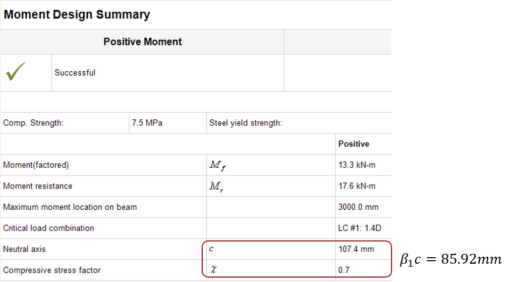
Below is a simple two course beam design that has been successfully designed for moment and deflection using a single No. 15 bar in tension and a tied No. 10 bar in compression. The resulting compression zone required to balance the tension and compression forces is 85.92mm based on a neutral axis depth of 107.4mm using a chi factor of 0.7 (recall that this is because the compression zone is entirely above the knocked out masonry webs of the top course.
When the knockout depth is changed from the default value of 100mm to 85mm (or slightly into the compression zone), the 0.7 factor can no longer be used. Notice that MASS correctly makes this switch automatically.
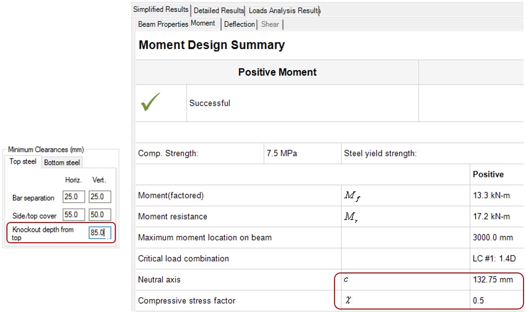
A couple things to take note of here:
- The neutral axis depth jumped from 107mm all the way up to 133mm, making it more difficult to satisfy the ductile failure requirement mentioned earlier.
- The moment capacity dropped slightly from 17.5kN*m to 17.2kN*m. This is due to a small reduction of the moment arm between the compression zone and tension reinforcement.
One other thing worth pointing out is that these changes had no effect on the total tensile force in the reinforcement or total compression force between the reinforcement and masonry.
How this can help with beam design
Understanding the process and variables behind masonry design makes it easier to find improvements and optimizations to your designs using MASS. This post has hopefully highlighted the benefit of having a compression zone contained entirely within the knockout depth.
Taking advantage of a chi factor of 0.7 introduces 2 benefits:
- Allows the steel to yield by raising the depth of the neutral axis, moving it further away from the primary tension reinforcement.
- Improves the moment capacity by increasing the moment arm between the primary tension steel and the compression zone.
It was mentioned earlier in the example demonstration that MASS uses the correct chi factor automatically so you might naturally be wondering why it’s worth the trouble of diving deep into this topic (other than expanding your engineering understanding, of course!).
The Takeaway
The important thing to watch for when designing masonry beams is the scenario where the compression zone depth is slightly greater than the knockout depth. When this is the case, the neutral axis can be raised a couple of ways.
Tie the top steel in the beam to use it as compression steel to reduce the area of masonry needed in compression.
Using steel in compression is a great way to raise the location of the neutral axis, provided that proper measures are taken to ensure that it does not buckle. By default, top steel is used only for serviceability and the “Tied” box shown below is not checked automatically. 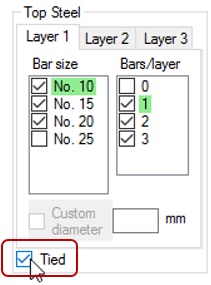
The CSA S304-14 specifies how to tie the compression steel:
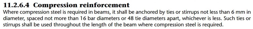
MASS does not perform detailing on masonry assemblages so it is left to the designer to ensure that beams satisfy this clause.
Use a higher strength masonry unit
No, this does not mean you also need to increase your grout strength (See note 4 of Table 4 within the S304 masonry standard for reassurance). Using a stronger unit has a similar effect as the higher chi factor, where the same compressive force can be resisted within a smaller area. If using a 20MPa unit is all it takes to get a successful moment design then it may be worth it!
Note that in most cases, higher strength units are readily available which is also a common designer misconception.
Final Thought
Most of the time, MASS will give a successful design before any of the default input values have been changed. By default, MASS will also attempt to optimize cost effectiveness however this process is as simple as attempting designs with smaller units before larger units, with less steel before more steel. The order and process of these optimizations are only meant as a starting point in working toward your final design. The chi factor is simply one the of many factors which makes beam design more complex and optimization less straightforward.
If you think that you have a design that can be optimized but you don’t know where to start, please do not hesitate to send your project to CMDC. What CMDC offers in Technical Assistance to designers includes offering some options and alternatives to consider for your masonry designs.