

What’s new in Version 4.3
Everything new in Version 4.3 summed up in one convenient place
National Masonry Design Programs, NMDP, is proud to announce the official release of MASS Version 4.3, which rectifies critical software bugs and updates MASS from NBCC 2015 to NBCC 2020.
This new version is available to all current license holders at no extra charge and can be downloaded for free using the link below:
Click here to visit the Downloads page
We have provided a detailed breakdown of the significant changes below, along with explanations for each. If there are questions regarding any of these changes, or the philosophy behind them, please feel free to contact technical support!
Jump ahead by expanding the contents section here.
Technical Changes
Updating to NBCC 2020
MASS has been updated from NBCC 2015 to NBCC 2020. There are many changes to the code but only a few that impact MASS itself. These include the addition of Serviceability Limit State (SLS) Load Combinations and changes to Seismic Provisions.
MASS v4.3 standardizes serviceability checks around NBCC 2020’s Table 4.1.3.4 SLS load combinations, replacing the prior patchwork of unfactored, ULS, and SLS approaches. Wherever SLS combinations are used, MASS now labels them with the “SLS” subscript (e.g., 1.0DSLS + 1.0WSLS).
Module behavior is now consistent: in the Shear Wall Module, seismic cases still use ULS combinations with a Seismic Drift Check per NBCC 2020 4.1.8.13, while all non-seismic cases use SLS combinations with the Wind Check per NBCC 2020 4.1.3.5(3). Additionally, the Out-of-Plane Wall Module evaluates wind with SLS combinations against CSA S304-14 10.14.3 deflection limits, while the Beam Module uses SLS combinations for CSA S304-14 11.4.5 deflection checks. The result is a clean alignment of deflection evaluations with NBCC-defined load combinations across the software.
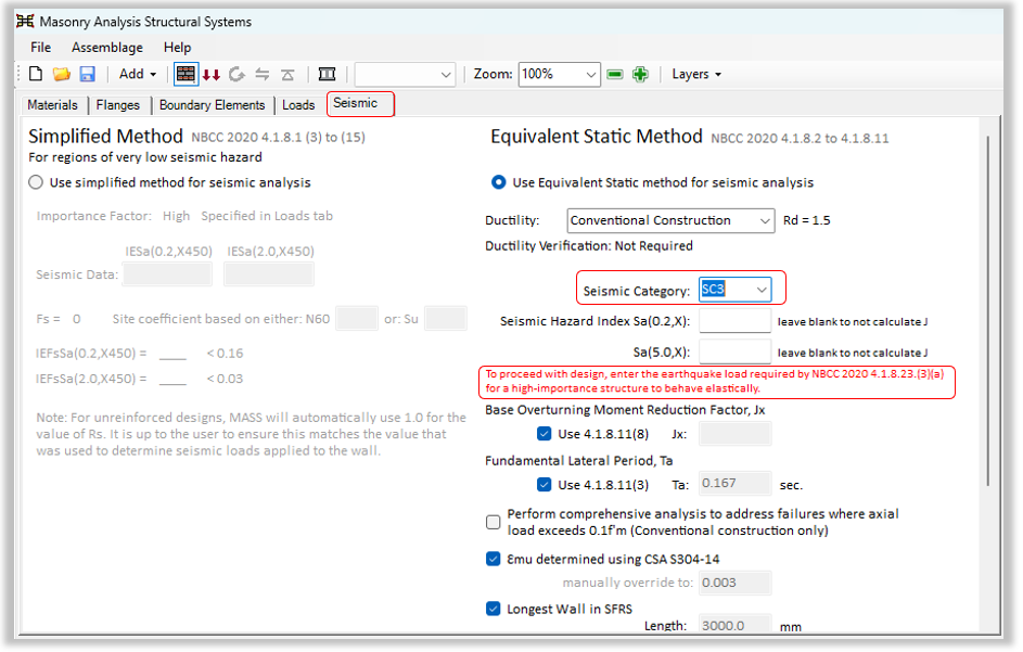
For load cases that include seismic loads and are analyzed using Clauses 4.1.8.2 through 4.1.8.11 of NBCC 2020, MASS adopts NBCC 2020’s Seismic Category (SC) framework. This framework is determined using the 0.2s and 1.0s spectral acceleration values—obtained from the NBCC Seismic Hazard Tool or site-specific reports—each scaled by the Importance Factor, IE. The site coefficient, Fa, is already embedded in the spectral acceleration values. To keep these limits internally consistent with the seismic category approach, MASS applies the harmonized Clause 17 limits from CSA S304-24 as guidance in determining which equivalent provisions of CSA S304-14 should be used. This approach supersedes the hazard-indexed limits of CSA S304-14 Clause 16 and reflects the rigorous technical review underlying S304-24, even though it has not yet been formally referenced in the building code.
NBCC 2020 4.1.8.10 adds system restrictions for high-importance buildings. To address this code change, MASS now enforces ductility minima for single-storey shear walls (Rd ≥ 2.0 in SC4, otherwise ≥ 1.5) and screens multi-storey high-importance designs for irregularities, disallowing Types 1, 3, 4, 5, 7, 9, and 10 in SC4 (MASS does not check 3, 4, 5, 7, 9, 10) and prohibiting Type 6 for all high-importance cases. Additionally, NBCC 2020’s updated Table 4.1.8.11 values have been added into MASS (higher Mv, lower J) which reduce base overturning moments in shear-wall design.
NBCC 2020 4.1.8.23 adds performance requirements for post-disaster and high-importance buildings, and MASS v4.3 performs two verifications. First, elastic-behaviour verification prompts the user to input the specified lateral earthquake force, V, as calculated in accordance with NBCC 2020 Clause 4.1.8.23 . MASS then compares the resulting factored shear and moment to nominal resistances per CSA S304-24 Clause 17.3.5.3. Second, interstorey drift is checked with IE = 1.0 and RdRo = 1.0, enforcing a limit of 0.005h per storey.
The SLS unification and seismic design updates deliver code-current results and a clearer workflow.
A dedicated post is available here, explaining this in full.
Self Weight on Out-of-Plane Walls
In prior versions of MASS, enabling the “self-weight” feature for Out-of-Plane (OOP) Walls applied the full wall weight as a lumped axial force at the top of the wall. While intentionally conservative for most scenarios, this assumption did not reflect the actual distribution of dead load along the height.
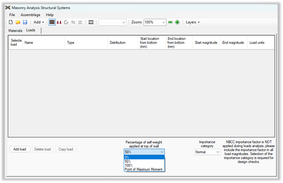
MASS v4.3 introduces finer control and more realistic modelling. Users can now specify the portion of wall self-weight to include—0%, 50%, or 100% of the full wall weight—and may alternatively compute self-weight at the critical section (the point of maximum moment). To streamline typical use, MASS sets a sensible default based on the selected boundary condition; users can override these values at any time.
| Boundary Condition | Default Percentage |
| Pin-Pin | 50% |
| Fix-Fix | 100% |
| Fix-Pin | 100% |
| Fix-Free | 100% |
These options retain the ability to remain conservative where appropriate while enabling designs that better capture the true effect of self-weight on OOP behavior.
Importance Factor
To simplify workflows and avoid double-counting, MASS no longer applies the NBCC importance factor, I, to user-entered loads. Because NBCC load generation procedures already embed the importance factor in the prescribed actions, requiring designers to divide it out before entry was error-prone and inconsistent. In MASS v4.3, you still select an Importance Category so the software can perform the required code checks and limitations, but the importance factor is not multiplied into load inputs inside MASS. For example, when calculating a Snow Load in accordance with NBCC 2020 Clause 4.1.6.2 (1):
S = Is[Ss(CbCwCsCa)+Sr]
We can see here the Importance Factor is already included in Load Determination, so this is the load that will be directly entered into MASS. This load will then be plugged into all ULS load combinations to determine the governing loading scenario.
For serviceability evaluations, MASS now applies SLS load factors automatically based on both load type and the selected Importance Category. When the user supplies a load that uses ULS importance factors, MASS internally removes the ULS factor and applies the correct SLS factor to generate service-level actions for deflection and drift checks. The result is a cleaner, more transparent load path that aligns with NBCC intent while reducing bookkeeping for the designer. To illustrate this, consider the Snow Load we calculated above used an Importance Factor of 1.15 (High Importance Category). When performing an SLS check, MASS adjusts this load by dividing it by 1.15 then multiplying it by the SLS Importance Factor, which is 0.9 in this case. This new SLS load will then be plugged into all SLS load combinations to determine the governing loading scenario.
Miscellaneous
Modulus of Elasticity of Masonry
Previously, if the modulus of elasticity calculated from the user’s f’m input exceeded 20,000 MPa (using E = 850 × f’m), MASS flagged the design as failing. In v4.3, MASS caps the modulus of elasticity at 20,000 MPa for analysis so the design can still be evaluated. The user’s entered f’m is unchanged; only the derived E is limited. For example, if f’m = 30 MPa gives E = 25,500 MPa, MASS now uses E = 20,000 MPa in accordance with CSA S304-14 clause 6.5.2.
Maximum Spacing of Vertical Seismic Reinforcement in Non-Loadbearing Walls
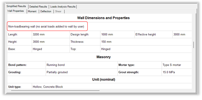
MASS now enforces maximum spacing of vertical reinforcement in non-loadbearing walls, in accordance with the note under Clause 16.4.5.2. This note specifies that the spacing limits of Clause 16.5.2 also apply to non-loadbearing and partition walls. The software determines the applicable maximum spacing from Clause 16.5.2 and applies it to non-loadbearing walls—a check that was not performed in previous versions. In addition, the Simplified Calculations section now states whether each wall is being designed as loadbearing or non-loadbearing.
Clause Fixes
MASS occasionally outputs the wrong CSA S304-14 clause reference when showing a failing design. Below are the ones that have been fixed:
- When a slender wall was designed and the axial load limit was exceeded, MASS v4.2 would tell you that the design failed due to clause 10.4.1 not being met. This has been updated to the correct clause 10.7.4.6.4.
- When the factored shear exceeded the shear resistance, MASS v4.2 would tell you that the design failed due to clauses 7.10.3 or 10.10.3 not being met. This has been updated to the correct clauses 7.10.2 or 10.10.2.
- When the horizontal bar spacing exceeded the allowable maximum bar spacing, MASS v4.2 would tell you that the design failed due to clauses 10.15.1.2 and 16.4.5.3 not being met. This has been updated to the correct clauses 10.15.1.4 and 16.4.5.4.
- When the factored shear exceeded the sliding shear resistance, MASS v4.2 would tell you that the design failed due to clause 10.10.5.2 not being met. This has been updated to the correct clause 10.10.5.1.
Significant Digits of Loads Entered into MASS
Previously, the Loads tab rounded input values to one decimal place. For example, an input of 36.45463 kN was shown as 36.5 kN, even though MASS used the exact entered value (36.45463 kN) in the analysis. This display/analysis mismatch could cause confusion during reviews. MASS now displays loads as they are entered (e.g., 36.45463 kN). Analysis methods and results are unchanged; this is a display-precision improvement only.
Ability to Rearrange Tabs
For large projects, many tabs can accumulate in a single file, though it is recommended to keep files small to minimize memory issues. This release allows designers to reorder tabs to match their workflow. The only caveat now is that when either the Shearline Module or the Multi-Storey Shear Wall Module is used, all pier tabs created by that module move together as a group to preserve their relationships. This is a usability and UI change only; analysis methods and results are unaffected.
Bug Fixes
Shear Wall – Shear Resistance of Moderately Ductile or Ductile Wall
For walls designated as Moderately Ductile or Ductile, the masonry contribution to shear resistance, Vr, was not reflected in the reported value of Vr due to the shear strength attributed to masonry, vm, not being calculated. All other ductility classes were unaffected by this behavior. This bug has been corrected in version 4.3, and vm is now calculated.
Beam – Bars Tied in Compression
Under Clause 11.2.6.4, the maximum stirrup spacing that can tie a 10M compression bar at the top of a beam is 160 mm. In standard CMU construction, cells occur at 200 mm spacing, so this requirement cannot be met when unmodified standard stretcher units are used for construction, and the design should fail with a reference to the clause. Earlier versions did not flag this condition.
A practical workaround for this issue is to employ high-lintel units, which accommodate the required reinforcement detailing. Users can define a high-lintel unit within the Material Database Editor and specify it as the selected block type. Using high-lintel units enables compliance with Clause 11.2.6.4 while maintaining 10M compression bars at the beam’s top.
Beam – Missing Support
Previously, some projects produced incomplete moment design results and resulted in shear failures because the left support condition was intermittently lost. Users could temporarily restore correct results by toggling the left support setting. Version 4.3 resolves this issue by preserving the left support state reliably, thus restoring full moment design output and correct shear checks without user intervention.